A Review- Modelling Approach and Numerical Analysis of Additive Manufacturing
(This article belongs to the Section Mechanical Engineering (MEE))
Export Citations
Cite
Kohale, V. , Jawade, S. and Kakandikar, G. (2022). A Review- Modelling Approach and Numerical Analysis of Additive Manufacturing. Journal of Engineering Research and Sciences, 1(3), 116–125. https://doi.org/10.55708/js0103012
Vaishnavi Kohale, Samidha Jawade and Ganesh Kakandikar. "A Review- Modelling Approach and Numerical Analysis of Additive Manufacturing." Journal of Engineering Research and Sciences 1, no. 3 (March 2022): 116–125. https://doi.org/10.55708/js0103012
V. Kohale, S. Jawade and G. Kakandikar, "A Review- Modelling Approach and Numerical Analysis of Additive Manufacturing," Journal of Engineering Research and Sciences, vol. 1, no. 3, pp. 116–125, Mar. 2022, doi: 10.55708/js0103012.
Additive manufacturing creates 3-dimensional objects by depositing materials layer by layer. Different applications of additive manufacturing were examined to determine future growth possibilities. The current research seeks to discover existing additive manufacturing techniques based on the process mechanisms, evaluate modelling approaches based on modelling methodologies, and identify required studies. A significant number of numerical simulations are conducted to evaluate the thermal FE structure in terms of solid and powder material thermo – physical properties and permissible boundary conditions. The transient heat conduction is investigated using thermal analysis with a moving heat source.
1. Introduction
Nowadays, industrial 3D printing is a slow and costly trial and error process. On the other hand, additive manufacturing is a group of manufacturing technologies that use a solid digital model to produce an item additively. The interaction between solid models and additive manufacturing, as well as material deposition, are entirely computer-controlled. The method, which is based on CAD models, can manufacture reliable yet complicated parts. Moreover, it pushes towards a tool-less manufacturing environment, which means better quality and efficiency in many circumstances. 3D printing, freeform fabrication, and additive fabrication terms are used for representation of additive manufacturing. Low-Vol. components with complicated forms and geometric characteristics have traditionally been produced using traditional additive manufacturing methods. However, SLM technology allows for creating geometries with complex features that are impossible to achieve using conventional production processes such as casting, powder metallurgy, forging, and extrusion.
1.1. Additive Manufacturing
The process of joining materials to make objects from three-dimensional model data, usually layer upon layer, instead of subtractive manufacturing methodologies i.e traditional machining is defined as Additive manufacturing (AM) [1]. The AM manufactures component layer‐by‐layer deposition using a laser. Using computer-aided design (CAD), additive manufacturing has the freedom to create objects with complex geometric shapes. Each process will differ depending on the material and machine technology used. Many additive manufacturing processes are available. The processes differ in the manner in which layers are deposited to form a component in the working principle and the materials used. The additive manufacturing method emerged as the primary tool in rapid prototyping. Continuous filament of a material is used in Fused deposition modelling (FDM) [2]. In DED method for Inconel 718 material the unique Mechanical properties and energy storage capacity are improved with the application in nuclear energy, Oil & gas. For powder bed fusion manufacturing in 316L stainless steel material the improved properties are better radiation tolerance and lower IASCC susceptibility for application of nuclear energy, Oil & gas [3]. Because materials for AM systems are limited, research and development are continuing to broaden materials and the application of present metal AM processes to a wider spectrum of materials. Polymers, ceramics, and metals are among the materials that can be used in AM technology [4]. Researchers and companies are becoming more interested in metallic materials among these materials.
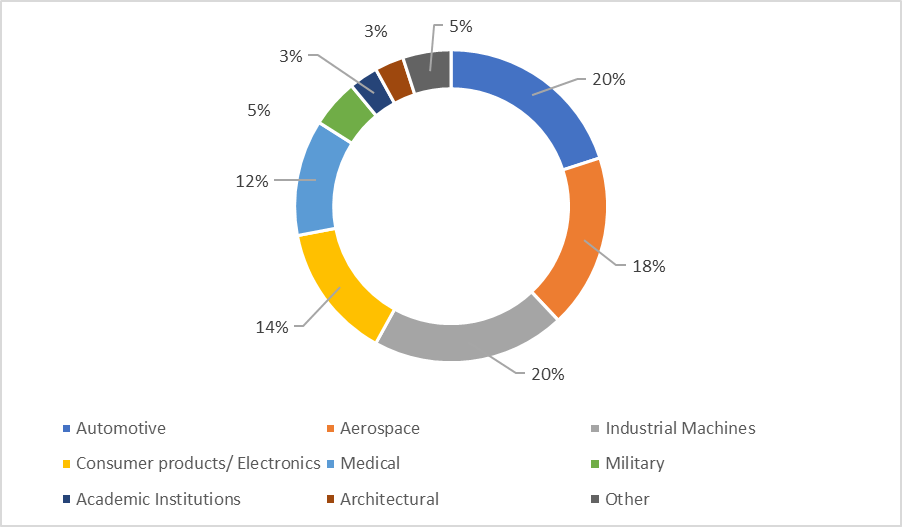
1.2. Applications
- Aerospace– Laser-sintering meets commercial and military aircraft demands for air ducts, fittings, and mountings that carry special aeronautical equipment.
- Manufacturing– Laser sintering is a cost-effective way to service specialized markets with low Vol.s. As economies of scale do not affect laser sintering, manufacturers may focus about batch size optimization instead.
- Medical– Medical gadgets are high-value, complicated goods. They must precisely fulfil the needs of their customers. These criteria must be met not just because of the operator’s personal preferences but also because of regionally differing legal requirements or conventions. As a result, there are several varieties and, as a result, tiny amounts of the variants available.
- Prototyping– Laser-sintering allows the creation of both design and functional prototypes. As a result, functional testing may begin immediately and with greater flexibility. Simultaneously, these prototypes may be utilized to assess consumer acceptability.
- Tooling– The natural method removes the need for tool-path generation as well as various machining techniques like EDM. Tool inserts can be made overnight or in a matter of hours. Furthermore, design flexibility may be used to improve tool performance, for as by including conformal cooling channels within the tool.
2. Modelling approach and Numerical analysis
An abstract description of a process that creates a relationship between input and output values is referred to as a model. Models that seek to predict the performance of the real system simulate it. Modeling involves making a 3D model data. Methods used for modelling and numerical analysis are:
2.1. Process modelling
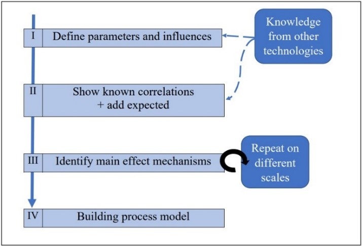
The majority of technology process models are classified into one of three categories. Three models are possible: white box or simulation models – are built utilizing physical relations and engineering expertise to describe the process at the needed level, black box models – To describe a process, use data or knowledge collected from studies, grey box models – while still reasonably easy to solve, also include details than an equivalent black box model [5]. The interaction amongst the laser beam and even the powder material is perhaps the most typically modelled element in laser-based powder bed technology. Models at the powder scale are frequently used to determine the required laser input energy and can also be used to explore specific phenomena such as melt pool temperature histories or microstructures [5]. The figure 2 shows overview of approach.
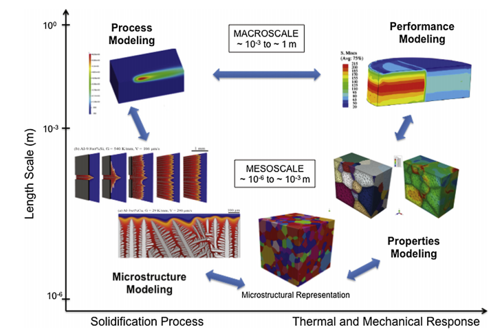
There are two primary additive manufacturing technologies: powder-bed and directed energy deposition. Material deposition is confined and happens concurrently with laser heat deposition in direct energy technology, whether powder fed or wire fed. Computational Fluid Dynamics (CFD) is used for non-linear partial differential equations for macroscale simulation of the solidification process [6]. In direct energy deposition, a continuum thermo-mechanical modelling tool is used to simulate the melt pool shape. Melt pool calculates the process’s stability based on the powder layer thickness, scanning velocity, and optical and thermal characteristics of the material. Methods used are coupled radiation, heat transfer, consolidation kinetics, conventional radiation transfer equation [7]. For simulation of melt pool geometry finite element method, Discrete Element Method and fluid flow simulation and a 3-D transient heat are approached. During processing, finite-element analysis software i.e Finite-Element Analysis (FEA) is utilized to solve the coupled governing equations for solid deformation and heat transfer [6]. The proposed integrated process structure properties performance modelling and simulation methodology is presented in fig 3 [6].
The temperature distribution in a single powder process is defined using a finite element-based heat transfer model. The geometrical characteristics of a single-track configuration have been quantitatively studied [8]. The created simulation model determines how process factors affect geometric features. Investigators have recently been drawn to wire-arc manufacturing processes (WAAM) in order to build metal parts with a higher deposition rate. A framework for component certification based on international standards have been developed using a computationally efficient mathematical model metho for the metal-AM process [9]. Manufacturing companies have embraced directed energy deposition technologies because of their capacity to build significantly bigger mechanical and structural components directly from a CAD model. 3D CAD model generation, slicing 3D CAD model to acquire set of 2D geometries, producing tool path for each one of these 2D geometries, selecting deposition parameters for every layer, selecting welding parameters such as travel speed, voltage, feed rate, and so on are all part of the process planning [10]. Finally, using the WAAM process and the supplied parameters and tool route, the products can be deposited. To build 2D geometries from a 3D model, there are two methods: unidirectional slicing and multidirectional slicing. Due to its ability to produce big and slightly less difficult geometric components, WAAM methods are conquering the industrial industries. The WAAM process is highly recommended for low and medium complicated geometry component manufacture. Mesh-based approaches and mesh-free methods are the two types of numerical modelling methods [9]. To avoid wasting time and money on hit and trial testing, the use of FEM has been extended to the models of WAAM processes and their parametric optimization. At the macro-scale level, WAAM processes use a multi-physics continuum modelling method. the applicability of its versions on an industrial scale, including the multi-physics continuum modelling method at the macroscale, i.e., a thermo-mechanical model to estimate residual stress and distortion in WAAM-produced components. The numerical modelling aids in the understanding of the physics participating in the WAAM process, allowing it to be improved and changed in the field. The thermo-mechanical model’s fundamental bifurcations are the thermal and mechanical models [9]. It is further characterized as coupled and decoupled, poorly coupled or uncoupled model based on the interconnection amongst two models.
2.2. Microstructure evolution modelling
Quantitative predictions of microstructures that are additively manufactured, and therefore their performance and properties, will necessitate collaborative work in solidification modelling at many lengths and time. For modelling microstructure evolution, the Potts Kinetic Monte Carlo technique in the simulation of melt pool geometry. EBSD data and the open-source tool DREAM3D is used to generate the microstructure representation [6].
2.3. Performance modelling
For representation of accurate physical quantities recording and tracking the evolution of metallic materials, physically-based macro-scale continuum models are created. There might be a variety of physical factors at issue, any of which could be contributing to this variation in behaviour. Finite-Element Analysis software (FEA) like Diablo and ABAQUS, are used to solve the governing equation that represents the physical mechanisms in performance modelling [6].
2.4. Topology optimization
Different types of tools are used for topology optimization. A recently used tool for the detection of shapes is the PLATO tool. However, the development of optimization software has focused chiefly on geometric optimization which can be simulated in ANSYS. The software will include numerous constraints meant for processing parameter to achieve optimal material performance as well as optimized topology in future [6].
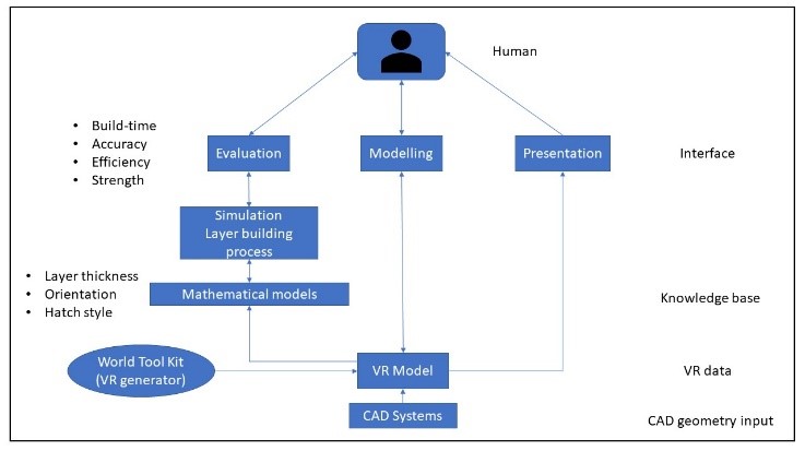
The optimization of rapid prototyping is estimated using various processes such as virtual prototyping and virtual reality, virtual simulation, virtual fabrication, modelling module, simulation module, evaluation module. Fig shows the virtual system representation of rapid prototyping. In addition, process parameters such as nuisance, constant and control parameters, hatch space, orientation, layer thickness, overcure depth, build time, hatch style is considered [11].
2.5. Multiphysical modelling
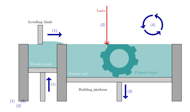
For simulation of selective laser sintering process as shown in fig 3 for single layer of particles, a multiphysical modelling technique is used. Mechanical and thermal interactions of particle-to-wall and particle-to-particle are studied using a discrete element method by Beer-Lambert Law. Powdered particles to be sintered are represented by individual spheres of various sizes in a discrete element model. The technique used to solve and analyze the Runge-Kutta scheme. The process parameters used for simulation are Particle Diameter, Domain Cross-Sectional dimensions, Number of Particles, Initial Powder Temperature, Scan Speed, Laser Power, Particle Density, Laser Beam Diameter, Melting Temperature, Vaporization Temperature, Thermal Conductivity, Heat Capacity [12].

The surface-tracking approach used in this class of CFD models allows for explicit depiction of individual powder particles, which is particularly useful for the L-PBF process. In this case, unlike earlier models, the material properties of the powder layer will be similar to that of the bulk stuff. In their CFD simulation, they apply the Lattice Boltzmann Methodology (LBM). ALE3D is used to create a FEM-based CFD model for the L-PBF process of 316-L stainless steel (Arbitrary Lagrangian Eulerian code) [13]. CFD model based on Finite Vol. Method FVM for IN718’s and aluminium L-PBF process is also developed. The influence of linear energy density here on creation of porosity in IN718 during L-PBF using the FVM model and Marangoni effect with recoil is also implemented [13]. There’s also a subset of multiphysics models that don’t use a surface-tracking method and then use a Lagrangian explanation of such melt pool surface layer. These models can forecast the creation of porosity and trace the metallurgical evolution throughout the process. Recent multi-physics models, on the other hand, have a number of drawbacks.
2.6. Multi-scale modelling approach
In the L-PBF process the Build-up model, single laser track model, multi-scale approach, single layer model is used to study the various process parameters, melt pool dimension, temperatures through layer solidification applied heat input load parameters [14]. In addition, the method is used to calculate the process related to thermally induced distortions.
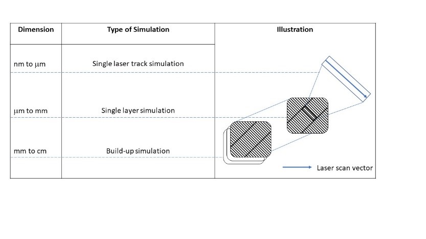
To accomplish quick distortion prediction for MAM parts, a multi-scale simulations framework was created. Three models at various scales are included in the framework. First, a micro-scale heat source modelling is used to calibrate the heat input. The heat input is then used to determine the intrinsic stresses using a meso-scale hatching model. The inherent strains are then used to a macro-scale layer model to anticipate the part’s distortion. Multi-scaling methods- AG (agglomerated heat source), MS (multi-step method), FH, SFH (flash heating and sequential flash heating), AMR (adaptive mesh refinement) [13]. Flash heating (FH) is a multi-scaling approach for parts that is focused on the layer-lumping principle. A section is splited into a particular number of pieces is along build direction in this manner. These chunks are actually a collection of actual layers that have been fused together and are referred to as meta-layers [13]. The meta-layer size is a model input variable that can be changed.
2.7. Hole-drilling method
In the L-PBF process, the Integral Method determines the residual stresses in the sample thickness. In this process the criteria used to choose the dimensions and geometries of specimens are stated as follows: Using traditional and easily measurable geometry, closed and open sections, thin-walled sections, flat surfaces, alignment along the normal or in the building direction, surfaces big enough to contain the strain gauges for the testing without suffering from edge effects induced by sharp edges [15]. Then, MATLAB estimates the residual stresses measurements. The advancement of the specimen’s stress profile is shown as a function of specimen geometry, in terms of open/closed sections and orientations.
2.8. X-ray (EDX) mapping
The SLM technique includes scanning a powder bed with a laser beam to manufacture layer by layer. The microstructure and nano-mechanical properties of the material is studied. Then, the changes in scan speed influence the development of fusion lines and single tracks. Energy dispersive X-ray (EDX) mapping is used to compare the SLM material’s chemical composition distribution [16]. To describe the mechanical characteristics of SLM-processed materials and assess the impact of process-induced defects heat treatment method is used. The material is processed under the SLM machine and AutoFab software. With increasing laser scan speed, the diameters of SLM-formed lines and tracks decreased linearly. Furthermore, abnormalities are identified at high scan rates [16].
2.9. CFD simulation
The high-speed imaging and CFD simulation are used for systematic parametric study to investigate the influence of laser scanning speed and powder layer thickness on porosity development and correlate porosity development with top sample surface and melt pool and flow behaviour. High-speed imagery and computational fluid dynamics (CFD) calculations were used to investigate the interaction between the powder particles and laser beam. C++ open-source the CFD toolbox called Open Field Operation and Manipulation, a simulation of the interaction between the laser heat source and the powder material is carried out [17].
2.10. Finite element modelling
To be more precise, statistical analysis and machine learning both require a large amount of data. Machine learning process parameters – Artificial neural network, Genetic Algorithm, Ensemble, Support Vector Regression. The statistical analysis method, that is Taguchi, ANOVA and regression modelling, two-level factorial design of experiment by Minitab software [18]. The mechanical performance of selective laser melting manufactured components is essential. The yield stress is the key characteristic, and it the main factor for the SLM manufactured component. Here the processing parameters such as laser power, scanning speed, and hatch space of an SLM process can be investigated [18].
During the Additive Manufacturing (AM) of metal parts, part distortion is a major concern. Finite element Modelling is used by AM for powder bed fusion manufacturing. The inherent strain technique is a quick and accurate approach for predicting residual stresses and deformation. The inherent strain method’s origins may be traced back to Computational Welding Mechanics, and it’s been widely adopted. It comprises of an FE quasi-static evaluation with user-defined inherent strains causing deformation [19]. To simulate the deformation of a twin-cantilever beam with different scanning tactics, a 3D simple mechanical model is created by using commercial software ABAQUS. The modelling methodology, namely layer lumping, allows for the usage of a rather coarse FE mesh. Two methods are applied for calculation of deformation purpose: Reduced order methods and Empirical methods [19]. An empirical methodology can be specified for determining characteristic inherent strains for just a specific scanning strategy, which are used as input data for linear-elastic analysis to derive distortion and residual stress fields generated by LPBF processes.
2.11. Mathematical modelling
In the RAM process the Deposition Principle and Establishment of Temperature Field Equation is required for the numerical simulation. The Gaussian distribution is analogous to the spatial accumulation distribution of mass flow [20]. By integrating the external mass supply element to the mass conservation equation, the mass growth process can be accomplished. The temperature field of a three-dimensional model must be generated using the Fourier law of conduction of heat and the principle of conservation of energy, and heat transfer problem’s governing equation must be established. The single-channel melting layer model using ANSYS is made and meshed. The temperature change of the molten layer under diverse currents was studied using a RAM simulation model, and indeed the present parameter range of the molten wire is preliminarily determined [20]. The actual physical events that occur during the AM process must be reduced to make the process available for numerical simulation. A Newtonian fluid present in melt pool is laminar and incompressible. Powder size follows a sphere-shaped Gaussian distribution. The flow at the solid-liquid interface is called mushy zones, regarded as a porous medium’s isotropic permeability. A Boussinesq approximation is used to evaluate the density fluctuation of the molten pool in the momentum equation for the buoyancy term.
- Gaussian packing
- Laser source and laser absorptivity
- Governing equations
- Boundary conditions
- Material properties and numerical simulation process
2.12. Heat transfer analysis
In the numerical modelling for the heat transfer analysis of AM operations using powder-bed method FE framework is utilized. To cope with the sintering process, that converts the metal powder into a new solid part, the formulation is reinforced with an appropriate FE activation approach. a good balance of computational effort and accuracy is achieved by simplified hatch-by-hatch patterns.
The governing equation for describing the temperature evolution of the AM process during the printing and cooling stages is the equation of balance of energy,
$$
H = -\nabla \cdot \mathbf{q} + r,
\quad \text{in } \Omega,\; t > 0
\tag{21}
$$
The temperature and the latent heat rate released or absorbed during the phase-change process are used to calculate the enthalpy rate per unit Vol.
- Boundary conditions.
The boundary conditions in the partition of the margines
where,
∂Ωc = surface contact with the printing platform,
∂Ωp = surface contact with the powder-bed,
∂Ωe = external surface in contact with the surrounding environment [11]
- Heat conduction through the building platform \
$$
T = T_c, \quad \text{for } \partial \Omega_c
$$
where Tc is the temperature of the building platform.
- Heat conduction in powder bed.
The density and the specific heat are straightforwardly computed as
$$
\rho_p = \rho_{\text{solid}} (1 – \phi)
\tag{21}
$$
$$
C_p = C_{\text{solid}}
$$
for low porosity powders,
$$
k_p
=
\left(
6.3 + 22\sqrt{0.09\,k_{\text{solid}} – 0.016}
\right)
\left(
\frac{k_{\text{solid}}(1-\phi)}
{\left(\dfrac{k_{\text{solid}}}{k_{\text{gas}}}\right)^{-(10.523 – 0.594\phi)} – 1}
\right)
$$
When the powder bed is excluded from the computational domain,
$$
q_p(T) = h_p (T – T_p),
\quad \text{on } \partial \Omega_p
$$
The numerical model provides for power input and absorption, heat dissipation across boundaries via conduction, convection, and radiation and temperature dependence of material properties.
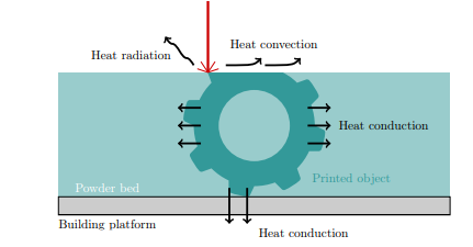
- Heat convection through the surrounding environment.
$$
q_{\text{conv}}(T) = h_{\text{conv}} (T – T_e),
\quad \text{on } \partial \Omega_e
$$
- Heat radiation.
$$
q_{\text{rad}}(T) = \sigma (T – T_e),
\quad \text{on } \partial \Omega_e
$$
For heat radiation and convection,
$$
q_{\text{loss}}(T) = h_{\text{loss}} (T – T_e),
\quad \text{on } \partial \Omega_e
$$
2.13. Thermo-mechanical model
The SLM manufacturing process is numerically analysed utilizing a 3D thermo-mechanical modelling method based on falter coupling. During the SLM process, this method allows for the assessment of both the mechanical stress distribution and the transient temperature.
- Heat transfer modelling
The first law of thermodynamics is used to develop the differential equation controlling transient heat conduction inside a continuous medium of arbitrary Vol. [22].
The heat equation gives the temperature with respect to time,
$$
k\left(
\frac{\partial^2 T}{\partial x^2}
+
\frac{\partial^2 T}{\partial y^2}
+
\frac{\partial^2 T}{\partial z^2}
\right)
+ q
=
\rho c_p
\frac{\partial T}{\partial t}
$$
where,
k = thermal conductivity coefficient,
ρ = mass density,
cp = specific heat,
q = power generated per Vol. in the workpiece.
A hemispherical shape heat source model’s power density distribution is represented by,
$$
\dot{q}
=
\frac{25\sqrt{2}\,P}{\pi^{3/2} r_0^3}
\exp\left(
-2\frac{x^2 + y^2 + z^2}{r_0^2}
\right)
$$
where,
P = power of the laser source,
β = absorptivity of the laser beam
r0 = radius of the laser beam.
- Mechanical modelling
The decoupled or poorly coupled approach is commonly employed for AM process modelling since it requires less computational effort and time than the fully coupled method. The mechanical or structure analysis stage, however, dominates the analysis time in decoupled modelling. Since the thermal gradient near the thermal source is extremely strong, the mesh size must be adequate to capture the high graded residual stress and distortion of the diffusion layer and many layers beneath it: in the heat affected zone (HAZ) [23]. As a result, when a fine mesh is used in the model, the computational time increases. To reduce the computational time of DMD, a Finite Element-based mesh coarsening technique is developed in both thermal and mechanical analyses. When compared to a traditional analysis process that used just fine meshes with no coarsening, the computing time for the coarsening method is reduced by around three times, and the findings are comparable. The ABAQUS solution map technique is used for meshing purpose. In two steps, the adaptable meshing technique is used: fine mapping and coarsening steps which utilizes the concept of coherent strain. The model can be separated into three separate scales (micro, meso, and macro), the mechanical layer equivalent can be achieved [23]. With a true thermal heat model structure and thermal boundary conditions, a pure thermal analysis is done on a very small structure that is connected to a substrate that replicates the lower layers from the real scale. Many AM factors that have a huge consequence on the mechanical properties of the parts produced demand more inventive FE-based modelling framework.
- Quasi-static mechanical analysis
It is carried out to obtain mechanical response of the workpiece.
The balance of linear momentum in any point of the body
$$
\operatorname{div}(\boldsymbol{\sigma}) + \mathbf{b} = 0
$$
where,
σ = stress tensor
b = body forces,
The sum of the following terms yields the total strain increment:
$$
\Delta \varepsilon^{\text{total}}
=
\Delta \varepsilon^{e}
+
\Delta \varepsilon^{p}
+
\Delta \varepsilon^{th}
$$
where,
Δ∈𝑒 = elastic strain increment,
Δ∈p = plastic strain increment,
Δ∈𝑒𝑡ℎ = thermal strain increment.
the resulting stress from the elastic strain.
$$
\boldsymbol{\sigma}^{e}
=
\mathbf{C} : \boldsymbol{\varepsilon}^{e}
$$
where,
C = fourth-order material stiffness tensor (Elastic moduli).
For the associated flow rule the plastic strain increment is,
$$
\Delta \boldsymbol{\varepsilon}^{p}
=
\lambda \frac{\partial f}{\partial \boldsymbol{\sigma}}
$$
where,
λ = plastic multiplier calculated through the consistency condition
The total thermal strain is calculated,
$$
\boldsymbol{\varepsilon}^{th}
=
\left(
\alpha_T (T – T_{\text{ref}})
–
\alpha_{\text{ini}} (T_{\text{ini}} – T_{\text{ref}})
\right)
\mathbf{I}
$$
αT and 𝛼ini = Vol.tric thermal expansion coefficients evaluated
T = current temperature
Tini = initial temperature respectively
Tref = reference temperature for the thermal expansion coefficients
I = second-order identity tensor
Numerical simulation can efficiently determine thermal development, molten pool shape, residual stress, and deformation. The model combines heat transfer and fluid dynamics to track the boundaries of melt pools.
The precise calculation of nodal temperature data, dispersion of residual stresses & deformation of components manufactured by AM, as well as large computational efforts, are the main issues in AM modelling. Innovative solutions are proposed and applied to address these challenges in metal alloy AM techniques, as well as modelling methodologies to increase the process’ efficiency and accuracy. residual stress and deformation evaluation of Direct metal deposition [23]. As the deposition progresses and multiple layers are created, the thermal expansion of layers under the heat source causes compressive pressures to be applied to the lower layers, resulting in compressive plastic strains. Because of the nature of the operation, stress residual induction is unavoidable in AM procedures. To analyse material deposition onto the substrate and the generation of residual stresses & geometric distortions in AM parts, the aforementioned models often use simplifying assumptions or employ particular methodologies.
The modelling of the AM process may be separated into two categories: (1) doing a pure thermal or thermal transfer analysis in order to acquire the nodal temperatures in the FE based model, and (2) building a structural configuration in order to evaluate mechanical behavior of the FE based model with applied nodal temperature gradients, and lastly, obtaining the deformation and residual stresses of the produced component [23]. The approach is known as coupled thermomechanical analysis when the thermal study is followed by a structural assessment for each increment. The approach is known as coupled thermomechanical analysis when the thermal study is followed by a structural assessment for each increment.
The heat transfer analysis is built on the idea of the body’s energy conservation. The residual stresses and distortions are estimated by applying boundary conditions to the mechanical FE model. Properties of the material should be considered temperature dependent in both the thermal or mechanical analyses to provide a more realistic representation of the process. The application of incremental material to the substrate necessitates the use of numerical analytical tools. The most well-known strategies are (a) silent elements activation, (b) inactive parts activation, and (c) hybrid elements activation [23].
2.14. Thermal modelling
The precision of the temperature history data produced through thermal analysis in the FE based decoupling approach for a model is critical for precise estimate of a residual stress distribution & deformation of an AM part. The thermal study of AM processes has been the subject of numerous studies. Various features and improvements in the modelling of thermal analysis with AM processes is given. The heat flux model, which represents the thermal source, is an important part of the thermal analysis. The laser/electron beam characteristics, such as power, speed, orientation, shape, and efficiency, must be included in the thermal source model. 3D super Gaussian, 3D Gaussian and 3D inverse Gaussian beams are three different forms of thermal body heat flux distribution [23]. Degrading the overall heat transfer phenomenon within the melt pool is one of the simple suppositions in the thermal evaluation of the AM process, which can lead to an overestimation of a nodal temperature history and, as a result, an overestimation in residual stresses. During an AM process, the shape and parameters of the melting pool have always been a critical component in determining nodal temperature, as well as deformation and residual stress measurement [23].
2.15. Interactive CAD modelling
The production of 3D patterns that may be tailored to the CAD model using generative algorithms in parametric modelling. GD has spread to a variety of industries, including architecture, jewellery, and industrial design. GD’s parametric modelling enables for the automated production of any project piece based on parameters. This means that certain algorithm-generated rule sets control the development and change of pieces inside a project [24]. Elements are drawn automatically based on user-defined algorithms, and parameters inside the algorithm can be changed. Using generative algorithms, it is possible to identify answers to difficulties that can occur with traditional CAD systems. In inclusion to reducing the structure, generative algorithms are used to simulate non-structural aspects. For the production of 3D patterns and Voronoi tessellations, two algorithms have been implemented [24]. The first allows to create patterns on complex surfaces, while the second helps in creating a Voronoi tessellation. The new methodologies enable for the modelling and modification of non-structural components, allowing for an interactive aesthetic assessment of the geometries formed [24]. Only the structural parts are subjected to FEM analysis. To overcome any non-convergence issues caused by high displacements during flexion and extension movements, explicit dynamic simulations are conducted [24].
3. Conclusion
A survey and evaluation of modelling techniques is presented in this work. The classification of AM methods is based on their working principle rather than the materials utilized. Following that, modelling processes in the field of additive manufacturing were presented and classified, not only based on the operating principle but also on the simulated process characteristic and the modelling technique. The most commonly used way for handling the challenge of dimensional accuracy is through empirical models and statistical approaches (ANOVA etc.). Mechanical characteristics and dimensional stability are often modelled using numerical heat transfer models, which focus on the melt pool and material phase transition, whereas build time has been studied both analytically and numerically. New features in the CAD modelling industry that can help solve challenges related to modelling in Additive Manufacturing.
Conflict of Interest
The authors declare no conflict of interest.
- Pinar Zorlutuna, Nasim Annabi, Gulden Camci-Unal, Mehdi Nikkhah, “Microfabricated Biomaterials for Engineering 3D Tissues”, Advanced materials, Volume 24, Issue 14, pp. 1782-1804, 2012, doi:https://doi.org/10.1002/adma.201104631.
- Panagiotis Stavropoulos, Panagis Foteinopoulos, “Modelling of additive manufacturing processes: a review and classification”, Manufacturing Rev, Volume 5, Issue 2, pp. 1– 26, 2018, doi:https://doi.org/10.1051/mfreview/2017014.
- Cheng Sun, Yun Wang, Michael D. Mc Murtrey, Nathan D. Jerred, Frank Liou, Ju Li, “Additive manufacturing for energy: A review”, Applied Energy, Volume 282, pp. 1– 18, 2021, doi:https://doi.org/10.1016/j.apenergy.2020.116041.
- Ana Vafadar, Ferdinando Guzzomi, Alexander Rassau, Kevin Hayward, “Advances in Metal Additive Manufacturing: A Review of Common Processes, Industrial Applications, and Current Challenges”, Appl. Sciences, Volume 11, pp. 1– 26, 2021, doi:https://doi.org/10.3390/app11031213.
- Sarah Müller, EngelbertWestkämper, “Modelling of Production Processes: Theoretical Approach to Additive Manufacturing”, Procedia CIRP, Volume 72, pp. 1524–1529, 2018, doi:10.1016/j.procir.2018.03.010.
- M.M. Francois, Wayne King et al., “Modelling of additive manufacturing processes for metals: Challenges and opportunities”, Current Opinion in Solid State and Materials Science, Volume 21, Issue 4, pp. 198-206, 2017, doi:https://doi.org/10.1016/j.cossms.2016.12.001.
- N.T. Aboulkhair et al., “On the formation of AlSi10Mg single tracks and layers in selective laser melting: Microstructure and nano-mechanical properties”, Journal of Materials Processing Technology, Volume 230, pp. 88-98, 2016, doi:https://doi.org/10.1016/j.jmatprotec.2015.11.016.
- A.V. Gusarov, I. Smurov, “Modeling the interaction of laser radiation with powder bed at selective laser melting”, Physics Procedia, Volume 5, pp. 381-394, 2010, doi:https://doi.org/10.1016/j.phpro.2010.08.065.
- Shekhar Srivastava, Rajiv Kumar Garg, Vishal S. Sharma, Anish Sachdeva, “Measurement and Mitigation of Residual Stress in Wire Arc Additive Manufacturing: A Review of Macro Scale Continuum Modelling Approach”, Archives of Computational Methods in Engineering, pp. 3491–3515, 2020, doi:https://doi.org/10.1007/s11831-020-09511-4.
- K.E.K. Vimal, M. Naveen Srinivas, Sonu Raja, “Wire arc additive manufacturing of aluminium alloys: A review”, Materials Today: Proceedings, pp. 1139-1145, 2020, doi: https://doi.org/10.1016/j.matpr.2020.09.153.
- S.H. Choi, S. Samadevam, University of Hong Kong, “Modelling and optimization of rapid prototyping”, Computers in Industry, Volume 47, Issue 1, pp. 39-53, 2002, doi:https://doi.org/10.1016/S0166-3615(01)00140-3.
- Rishi Ganeriwala, Tarek I. Zohdi, “Multiphysics modeling and simulation of selective laser sintering manufacturing processes”, Procedia CIRP, Volume 14, pp. 299-304, 2014, doi:https://doi.org/10.1016/j.procir.2014.03.015.
- Mohamad Bayat, Wen Dong, Jesper Thorborg, Albert C. To, Jesper H. Hattel, “A review of multi-scale and multi-physics simulations of metal additive manufacturing processes with focus on modeling strategies”, Additive Manufacturing, Volume 47, pp. 1-25, 2021, doi: https://doi.org/10.1016/j.addma.2021.102278.
- Chritian Seidal, Michael F.Zaeh, “Multi-scale modelling approach for contributing to reduced distortion in parts made by laser-based powder bed fusion”, Procedia CIRP, Volume 67, pp. 197-202, 2018, doi:https://doi.org/10.1016/j.procir.2017.12.199.
- Alessandro Salmi et al., “On the effect of part orientation on stress distribution in AlSi10Mg specimens fabricated by laser powder bed fusion (L-PBF)”, Procedia CIRP, Volume 67, pp.191-196, 2018, doi:https://doi.org/10.1016/j.procir.2017.12.198.
- Kurian Antony, N. Arivazhagan, K. Senthilkumaran, “Numerical and experimental investigations on laser melting of stainless steel 316L metal powders”, Journal of Manufacturing Processes, Volume 16, Issue 3, pp. 345-355, 2014, doi:https://doi.org/10.1016/j.jmapro.2014.04.001.
- Chunlei Qiu, Chinnapat Panwisawa, “On the role of melt flow into the surface structure and porosity development during selective laser melting”, Acta Materialia, Volume 96, Pages 72-79, 2015, doi:https://doi.org/10.1016/j.actamat.2015.06.004.
- Ivanna Baturynska et al., “Optimization of process parameters for powder bed fusion additive manufacturing by combination of machine learning and finite element method: A conceptual framework”, Procedia CIRP, Volume 67, pp. 227-232, 2018, doi:https://doi.org/10.1016/j.procir.2017.12.204.
- Iñaki Setien, Michele Chiumenti, Sjoerd van der Veen, Maria San Sebastian, Fermín Garciandía, Alberto Echeverría, “Empirical methodology to determine inherent strains in additive manufacturing”, Computers and Mathematics with Applications, Volume 78, Issue 7, pp. 2282-2295, 2019, doi:https://doi.org/10.1016/j.camwa.2018.05.015.
- Suli Li, Kaiyue Ma, Chao Xu, Laixia Yang, Bingheng Lu, “Numerical Analysis and Experimental Verification of Resistance Additive Manufacturing”, Crystals, Volume 12, Issue 2, pp. 1-32, 2022, doi:https://doi.org/10.3390/cryst12020193.
- Michele Chiumenti, Eric Neiva, et al., “Numerical modelling and experimental validation in selective laser melting” Additive Manufacturing, Volume 18, pp. 171-185, 2017, doi:https://doi.org/10.1016/j.addma.2017.09.002.
- Bruno M. Marques et al., “Numerical Analysis of Residual Stresses in Parts Produced by Selective Laser Melting Process”, Procedia Manufacturing, Volume 47, pp. 1170-1177, 2020, doi:https://doi.org/10.1016/j.promfg.2020.04.167.
- Farshid Hajializadeh, Ayhan Ince, “Short review on modeling approaches for metal additive manufacturing process”, Material design and processing communications, Volume 2, Issue 2, pp. 1-7, 2020, doi:https://doi.org/10.1002/mdp2.56.
- V. Ricottal, R. I. Campbell, T. Ingrassia, V. Nigrelli, “A new design approach for customised medical devices realized by additive manufacturing”, International Journal on Interactive Design and Manufacturing, Volume 14, pp. 1171–1178, 2020, doi:https://doi.org/10.1007/s12008-020-00705-5.