Micro Forming and its Application: A Critical Review
(This article belongs to the Section Mechanical Engineering (MEE))
Export Citations
Cite
Tiwari, N. , Kakandikar, G. and Kulkarni, O. (2022). Micro Forming and its Application: A Critical Review. Journal of Engineering Research and Sciences, 1(3), 126–132. https://doi.org/10.55708/js0103013
Neha Tiwari, Ganesh Kakandikar and Omkar Kulkarni. "Micro Forming and its Application: A Critical Review." Journal of Engineering Research and Sciences 1, no. 3 (March 2022): 126–132. https://doi.org/10.55708/js0103013
N. Tiwari, G. Kakandikar and O. Kulkarni, "Micro Forming and its Application: A Critical Review," Journal of Engineering Research and Sciences, vol. 1, no. 3, pp. 126–132, Mar. 2022, doi: 10.55708/js0103013.
In terms of manufacturing methods/processes, micro-manufacturing has received a lot of attention around the world. Micro-forming is one of the most widely used micro-manufacturing techniques. The micro forming is based on the properties of materials based on the process of shaping parts and object by mechanical deformation. Many efforts had been focused on micro-forming, in particular the deep drawing process, because of the method's ability to produce an extensive variety of products, particularly in its conventional macro-process. This method is used to create the majority of everyday items. Although efforts were made to develop micro-forming for industrial use, the technique was deemed to be insufficiently advanced. Much development effort was required, in particular, to design a completely computerized high-extent production micro-forming machine that is dependable and ready to perform always in terms of procedures, material handling, and tooling to assure effective micro-product production. Micro forming, which is discussed in this work, is also one of the often-used micro-forming methods in deforming procedures. Finally, in addition to continuing to improve micro forming, this study aims to investigate the essential methods of the Limit dome height test, Nakajima test, M K Model test, and deep drawing processes and their major concerns in a systematic manner.
1. Introduction
Metal forming, in addition to being a substantial industry in and of itself, is a pillar of modern manufacturing. Every year, hundreds of millions of tons of metal pass through metal forming processes all over the world. Metal forming accounts for 15-20% of the GDP of most industrialized countries. It also serves a social purpose by giving employment to millions of people. Bulk manufacturing of semi-finished and finished goods is a metal forming industry, which is one of the reasons why large-scale research and development advantages are feasible because even minor per-ton savings mount as much as sums.
Surface strain measurements were also used to determine the Forming Limit Diagram. For surface strain measurement, a circular grid on foil is required [1]. The forming limit diagram (FLD) illustrates metal formability in low-cost metal forming [2]. FLDs can be created by hemispheric punch-stretch tests and Marciniak cup testing. These experimental procedures required a significant amount of effort and time. To improve the efficiency of FLDs, some analytical methods are applied. Analytical methods, however, are unable to predict failure. A forming limit diagram (FLD) is a graph that shows the major strains (e1) at the onset of localized necking for all values of the minor strain (e2) [3].
Plastic deformation is used to create product shapes in the metal forming process. As a result, for enhancing methods studying the plastic flow properties of alloys and metals is critical. The power and constraints of plastic deformation in forming also affect the factor properties. Raw materials are supplied for other techniques by many forming techniques, which manufacture finished or semi-finished items. Steel facilities, for example, manufacture sheet metal that is utilized in automobiles and their parts. A variety of manufacturers used sheet metal material to create a wide range of residential and commercial products. Similarly, re-rolling mills use billets produced by steel manufacturers to roll into components such as angles, channels, and bars.
The formability analysis will be discussed, as well as its advantages. As well as the variables that affect sheet metal formability. Blank temperature, blank shape, punch velocity, Punch nose radius, blank holding force (BHF), die arc radius and spring back are some of the parameters.
1.1 Formability
The formability of the material is defined as the given ability of a sheet metal workpiece to go through plastic deformation to a provided shape without damage. The sheet metal forming methods are deep drawing and bending, flaws must be studied separately. The mechanics of the forming process determine the difference between these types of stamping techniques. The normal defects of the produced parts are presented for deep drawing.
1.1.1. Types of Sheet metal forming process
1.1.1.1. Limit dome height test (LDH)
The LDH method is the combination of both forming limit diagrams and simulated tests. LDH is the out-of-plane deformation method and is performed in different strain paths like uniaxial, plane strain, and biaxial [5]. Ghosh aimed to describe the height of the component as a function of the lowest strains that rectangular Nakajima specimens stretched on a hemispherical punch till fracture is based on Drewes’ observation [6]. A diagram is presented below, which was created by sketching an arc around the result of experimental points recorded with samples of various widths. The approach was later adapted by foreign researchers as the strip stretch test, and by USA research scholars as to the Limiting Height Test.
A formability index defined by LDH is the height of the part after planar strain. As compared to the heights achieved in other stages of tension, this is the lowest. Material property is the width of the specimen about plane strain. Brings lots of advantages, the method is rarely used in industry because of its wide range of LDH values and the considerable quantity of testing required.
1.1.1.2. Deep Drawing process
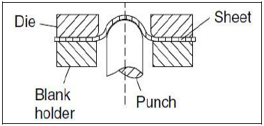
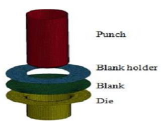
A sheet metal forming technique is known as a deep drawing that involves mechanically dragging a sheet metal blank radially into a forming die[2]. As a result, it’s a shape transition with material retention. When the sketched part depth exceeds its diameter, the procedure is known as deep drawing. This can be performed by redrawing the part with a series of dies. Deep drawing is a method for making cup-shaped objects, pressure vessels, and gas cylinders, among many other things [8]. The deep drawing test is also known as the micro deep drawing test (MDD). The MDD toolset was controlled by PLC modules in the control and data logging box, which have driven by the press machine [9].
1.1.1.3. Nakajima test
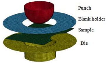
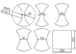
These tests involve a hemispherical punch to deform sheet metal blanks of various shapes until a fracture occurs [10]. The means growth using a circular die and hemispherical punch to create rectangular specimens of various sizes. The positive and negative domains of the FLD can be obtained by altering the specimen width and lubricant. The test’s benefits include the ease of use of the equipment, the square shape of the samples, and the ability to cover the whole Forming Limit Diagram (FLD) [11]. The possibility of wrinkling and measurement error caused by the punch’s shape are disadvantages. The ISO 12004 standard ‘Metallic materials’ uses this procedure as a standard method. The formation of limit curves is determined.
1.1.1.4. M K Model
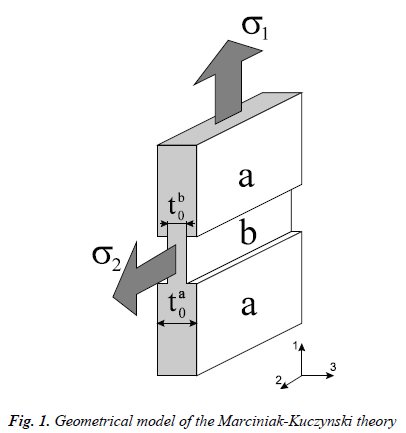
The M K Model theory is invented by professor Marciniak and Kuczynski in 1967. A model to investigate instability based on the assumption that there was a pre-existing flaw in the plane of metal sheets before deformation was suggested by Marciniak and Kuczynski. According to the hypothesis of Marciniak, sheet metal has formed manufacturing geometrical thickness variation and structural imperfection composition and gap. The defects gradually involve plastic forming of the sheet metal that is fully focused on having necking of sheet metal. The initial inhomogeneity factor is assumed in the direction perpendicular to the maximum principal stress. Hutchinson invented the M K model to detect FLD, by considering the arbitrary angle between minor principal stress and the imperfection. The M K model’s limit strains are sensitive to geometrical imperfections, and this magnitude is far too large for limit strain prediction to be useful. At a high strain ratio developed limit strains are overestimated. The M K model was created to solve this problem by including surface roughness and void growth in the imperfection hypothesis [6].
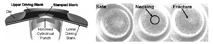
By using Nakajima set up biaxial stretching cannot obtain therefore Marciniak setup has been designed. The main difference between them is the shape of the punch. The Nakajima test uses spherical punch while the Marciniak test uses flat shape punch. Marciniak also developed a specific design: one or more additional sheet metal rings are used to prevent the punch from making contact with the blank. This test is difficult in practice because a hot blank from the furnace must be introduced between two cold carrier blanks in a very short amount of time. This is why a finite element analysis was performed to examine the strain distribution and optimize the driving blanks such as material and central hole diameter[6].
2. Effect of parameters
The smooth and defect-free operation of sheet metal forming is dependent on the selection of various process parameters. Studying forming in sheet metals is made easier with the use of the circle grid analysis and forming limit diagram (FLD). The above-mentioned process parameters, as well as their combinations, have been discussed in terms of experimental and analytical approaches in this paper [12].
2.1. Punch nose radius
The impact of the punch nose radius on deep drawing. Six different punches with different nose radii were utilized to create a cylindrical with a 44mm outer diameter (OD), a 28mm height, and a 0.5mm sheet thickness of mild steel with 0.15% carbon. The results reveal that it costs substantially more to create pieces with large nose radii than it does to form parts with small punch nose radii. Due to the significant stretching of the metal over the punch head, the hemispherical punch straightens the most [12].
2.2. Blank Temperature
On the deep drawing properties of the aluminum 7075 sheet, the effect of 3 main deep drawing process parameters: punch velocity, blank temperature, and die arc radius was studied [12].
2.3. Blank Holding Force
The behavior of wrinkling and the limiting drawing ratio with sheet thickness was studied by varying the blank holding force. The amount of blank holding power required to eliminate wrinkling grew significantly as the sheet thickness dropped, according to the authors. When the sheet thickness was extremely thin, the coefficient of friction had a significant impact on the blank holding force. As sheet thickness fell, the limiting drawing ratio reduced rapidly below 0.04mm thickness. When the thickness of the sheet was extremely thin, the coefficient of friction had a significant impact on the limiting drawing ratio [12].
2.4. The initial blank shape
The effect of the original blank shape and holding force on the final part quality, such as wrinkling and breakage. From the point of view of damage and fracture, the oval blank shape was discovered to have the worst formability in the initial testing. The three blank shapes oval, oblong, and rectangle were evaluated, and a mute conclusion was formed [12].
2.5. Spring back
The spring-back tendency of material during sheet metal forming has been researched, with positive results for decreasing defects such wrinkling, earing, damage, crack, and fracture. According to the researchers, spring-back occurs at the V-region and die-lip of the die model [12].
3. Micro Forming
Miniaturization of products is a current trend in many fields of engineering, enabling product functionality to be performed in the micro-geometry to minimize volume, weight, contamination, and cost [13]. It’s a micro-fabrication process for micro components that makes use of metal’s superior mechanical and functional qualities, and it’s a significant forming technology that’s has been reduced in size to the micron size range, making it perfect for manufacturing. According to Yole Développement, the microelectromechanical systems (MEMS) industry in micro-manufacturing would grow at a CAGR of 7.5% for medical applications, 43.6% for telecom applications, and 11.0% for industrial applications from 2018 to 2024 [14]. Due to increasing miniaturization in a variety of fields, such as medical equipment, precision equipment, communication equipment, micro-electromechanical systems, and microfluidic systems, demand for small-sized products has grown significantly. Over the last 20 years, research into metal micro-forming technologies has improved. Embossing, micro-sheet metal forming, Micro-bulk forming, micro-hydroforming, surface engineering for die and tooling, laser-assisted micro-forming, and micro-sintering are some of the research and development activities included in these studies [13]
4. Limitations of Micro-forming
It’s critical to understand the process’s limiting parameters in industrial micro forming applications. The limiting issues could be related to the micro forming’s special characteristics. There is a lot of study being done on how to optimize the micro forming process [15].
Size Effect- It is known that size effects play a key role in micro forming processes, and as a result of size effects, many unexpected changes occur while handling micro-scale parts/work-pieces. All of the sources or causes of size effects have offered a distinct idea of their appearance, and scaling law explained the phenomena in which all of the characteristics (size and weight) change in a fixed relationship with the change in size effects. The conclusion is that because size effects characterize the micro-world, a study of size effects in micro-forming is required to analyze all deformation behaviors, including maternal behaviour, stress distribution, and wrinkle creation on the material surface [16].
The size effect had an impact on flow, and deformation behaviour’s needed to be looked into. Experimental studies on the influence of a few significant characteristics such as geometry and grain sizes on the degree of flow-induced defects in the micro forming process of pure copper were conducted in this research to see how size effects affect flow-induced defects. The microstructure and flow pattern in microscale extrusion of components with intricate shapes are investigated, as well as flow-induced flaws in micro forming of a planned part [17].
Grain Size Effect- Micro-forming processes have shown that insignificant elements in bulk materials, such as grain-size effects, should not be ignored. In the micro-forming world, studies have demonstrated that material behavior differs dramatically as the scale is increased. As a result, in any microform-related process, particularly micro-stamping, studies and analyses of each material used in the process must be considered essential to understand their behavior and associate their behavior with the process [18].
A material with a larger grain size has less strength than one with smaller grain size, according to the equation. This impact is entirely dependent on the material’s average grain size and is most significant in macro-scale materials. Despite their thinness, the examined strips can still be classified as macro-scale material due to their relatively substantial width and length [18].
Flow Defects- In the micro-extrusion process, irregular material flow causes flow-induced defects, which is similar to the scenario in the macro-forming process. The flow line, on the other hand, becomes more apparent as the specimen size increases [17].
Geometry Defects- The effect of geometry size on the formation of folding defects is greater than the effect of grain size. No matter what grain size is used, the folding defect in deformed objects significantly improves when the geometry size is reduced [17].
5. Research Work
In this paper Amin Teyfouri studied various micro forming processes. Micro forming is one of the frequently used micro-manufacturing methods in deforming processes. This study aims to analyze the key methods of stamping, forging, bending, and deep drawing processes, as well as their major challenges, in addition to continuing to improve micro forming [19]. By miniaturizing or downscaling, conventional and non-traditional techniques have been commonly used to produce micro-products. Subtractive, joining, hybrid, and deforming processes are the four types of general manufacturing processes. The capacity to produce parts with feature sizes of less than 100µm is the most massive benefit of micro-manufacturing. High-volume production should be a primary consideration when developing micro-manufacturing in micro-components. More study is needed to improve micro-forming methods, especially deep drawing and bending processes, as well as more basic research on the interaction of handling tools and materials.
In this work V. Chowthies said that further research is needed to improve some micro forming methods especially deep drawing and bending processes, as well as more fundamental research into the interaction of handling tools and materials [20]. Micro-manufacturing will become a stronger link between macro-manufacturing and Nano-manufacturing in the future due to developments in machining and handling technology.
In this research paper Tsung-Chia Chen presents an analysis of the deep drawing technique for stainless steel micro-channel arrays is presented. The fuel flow field, electric connectivity, and fuel sealing are all performed by the micro-channel of bipolar plates. The updated degenerated shell finite element analysis, Lagrangian formulation, and the r-minimum rule investigates the major link between punch load and stroke, strain, and stress distributions, thickness fluctuations, and depth variations of individual micro-channel sections. The depth and width of a single micro-channel are 0.5 mm, 0.75 mm, respectively, and a micro-channel array is effectively formed [21]. Fractures were most usually seen in the micro-channel bottom’s fillet corner. According to the results of the experiments, greater consideration should be given to the punch and die fillet dimension design. A bigger die fillet can contribute to improved formability and a lower punch load.
In this paper Fanghui Jia tested MDD experimentally and numerically to better understand the microscale deformation behavior of a 2-layer Al-Cu composite. The composite material was rolled to a thickness of 50 m [22]. The annealing of material is then carried out at 400°C. MDD experiments were used to evaluate the draw-ability of the annealed composite. For simulation of the composite material through the micro deep drawing process, FE models with Voronoi tessellations were developed. To account for the grain heterogeneity, several mechanical characteristics have been assigned to each Voronoi tessellation based on experimental data. The results of the simulation are very similar to the experiment results. With the MMD technique, micro components can be manufactured, and the resulting cup has no fractures and fewer wrinkles. To improve the accuracy of FE simulation, grain sizes of Al and Cu can be immersed into the Voronoi model. The result of the FEA analysis with the Voronoi diagram is closer to the experimental result in terms of drawability (cup mouth wall thickness, flange height, and cup mouth radius), wrinkles, and drawing force [22].
In this research work N. Srinivasan analyzed the integration of growths from the macro to the micro-scale using progressive micro forming techniques, focusing on the size effect deformation behavior in materials, dimensional accuracy, deformation load, failure analysis, and roughness of micro components, all of which are related to micro-scale forming processes such as extrusion, forging, and incremental [23]. The research challenges of micro mass production related to industrial complexity, as well as the micro forming process that requires extensive attention, are discussed. For medical applications such as prosthetic teeth, the study should be extended to include other metals such as magnesium and titanium, and the effect of size on material behavior will be profoundly studied.
In this work A Dhal study shows that refined microstructures have good micro forming capabilities in a variety of deformation domains (0.7 mm to 0.1 mm) [24]. The micro forming capability of micro-scale sheet metal forming is very sensitive to plastic instability. As a result, a finer microstructure with good strain hardening properties is desired. Cry rolling causes a significant amount of dislocation, which must be relieved with annealing. Microscale sheet metal forming requires a refined microstructure with dislocation-free, equiaxed grains.
In this research paper Dr. R. Sridhar focused on recent research and findings in the field of deep drawing. Deep-drawing processes are used to create a product that is light in weight, strong, low in density, and corrosion-resistant. These criteria will make the product more subject to wrinkling and other types of failure. Deep drawing is affected by several parameters such as blank-holder pressure, die radius, punch radius, coefficient of friction, and material characteristics [25]. To develop a defect-free product, a full understanding of the complete process is essential. The researcher aims to gather the latest advancements and research in the field of micro deep drawing. The main process factors and their impacts on micro deep drawing have been critically studied. Material thickness, coefficient of friction, thermal characteristics, stress and strain concentration, and wrinkling are shown to be important process parameters. Micro deep drawing of thin foil materials is found to be profitable for vehicle and electrical applications.
In this paper Sridhar Ramasamy studied the formability of pure copper foils, as well as the thickness distribution in micro deep drawing. The limit drawing ratio is obtained by selecting pure copper C1100 foil thicknesses of 100, 200, and 300 m [26]. A micro deep drawing tool assembly is created to determine the forming depth in microscale, as well as the force, required informed items. In both the tensile and Ericson cupping tests, the results show that 300 m foil has good formability. The cup shoulder corner and the upper section of the sidewall are where there is an excessive loss in thickness. In the transverse direction, the thinning is most visible at the cup’s sidewall. The research shows that with the right forming settings, high-quality copper micro cups may be made quickly. A fundamental understanding of the micro-deep drawing technique is established. Furthermore, it has been discovered that scaling effects must be considered not just inside the process but also in all other aspects of the forming process. Various copper foil thicknesses are based on micro drawing tests.
In this work the authors study project work is related to micro-farming research on a 90-micron ultra-fine brass sheet is used to mark FLD according to the ASTM E2218-02 limit dome height test. The experimental apparatus was designed and invented to perform micro-form standard specimens using a 15 mm hemispherical shape of the punch [13]. The failure limit curve for FLD shown with experimental and empirical methodologies shows agreement. Many industries, including medical instrumentation, automotive, mobile manufacturing, and aerospace, have embraced miniaturization. In the forming process, appropriate strain distribution promotes higher-quality products. To plot major and minor strains as well as form limit curves, the forming limit diagram (FLD) was contrived. FLD, in other words, exhibits localized necking, wrinkling, and safe zones with varied strain routes, and it proves to be a useful tool for determining the material’s rupture properties. Empirical (analytical), numerical, and experimental ways to plot FLD are available.
In this research the authors studied a new micro deep drawing approach for making micro-cups that combines a floating ring which acts as the principal rigid die, while a rubber pad acts as the primary flexible die [27]. The floating ring’s goal is to defend tiny wrinkles from forming at the flange, while the flexible die’s job is to finish the forming stroke. Simulations and tests are used to investigate the effects of drawing ratio, initial sheet thickness, rubber height, and punch corner radius. In addition, three size scales are used to test the feasibility of applying the suggested technique to various process dimensions.
In this research the authors experimented with the forming limit curves, fine alpha brass sheets of 40 m and 90 m with different orientations to rolling directions (0°, 45°, 90°) were subjected to an experimental test [28]. According to ASTM-2218-14, a hemispheric punching test for micro forming is done. A standard test was done using a sample of Single-Axial, Intermediate Single-Axial, and Two-Axial, Intermediate Two-Axial, and Plane Strain pathways to determine limit strains. The micro-forming process is modeled using explicit dynamic numerical analysis on the Abaqus platform and forming limit curves are displayed. Experimental data have been used to validate numerical results.
6. Conclusions
In this paper, High-volume production should be the main consideration when developing micro-manufacturing in micro-components. Currently, the majority of sheet metal research is focused on establishing the failure limit diagram using finite element methods, experimental methods, numerical analysis, and sheet metal material management. As described in this paper, additional research is needed to improve micro-forming methods, particularly deep drawing and bending processes, as well as more basic research into the interaction of handling tools and materials.
This paper explains the micro forming and various micro forming processes. This paper also discussed the effect of process parameters are punch nose radius, Blank temperature, spring back, and blank holding force.
- Gyan Patel and Ganesh Kakandikar, “Investigations on effect of thickness and rolling direction of thin metal foil on forming limit curves in microforming process,” in Modern Manufacturing Processes, (Elsevier, 2020), 145–155, doi:10.1016/b978-0-12-819496-6.00007-5.
- U. V Mangudkar, S. P. Mankani, “COMPARATIVE STUDIES ON FORMABILITY ANALYSIS IN METAL FORMING,” IJRET: International Journal of Research in Engineering and Technology. .
- V. R. Shinge, U. A. Dabade, “Experimental Investigation on Forming Limit Diagram of Mild Carbon Steel Sheet,” Procedia Manufacturing, vol. 20, pp. 141–146, 2018, doi:10.1016/j.promfg.2018.02.020.
- M. S. Kulkarni, S. Y. Gajjal, “Review of Sheet Metal Forming Analysis,” SSRG International Journal of Mechanical Engineering, vol. 2, no. 1, . 2015.
- J. Sahu, S. Mishra, “Limit dome height test of very thin brass sheet considering the scaling effect,” Journal of Physics: Conference Series, vol. 734, no. 3, 2016, doi:10.1088/1742-6596/734/3/032114.
- D. Banabic et al., Sheet metal forming processes: Constitutive modelling and numerical simulation (Springer Berlin Heidelberg, 2010).
- J. M. K. Rao, “Numerical Simulation for Predicting Failure in Deep Drawing Process Using Forming Limit Diagram ( Fld ),” no. 4, pp. 11–15, 2015.
- J. Pavan Kumar et al., “Formability of sheet metals – A review,” IOP Conference Series: Materials Science and Engineering, vol. 455, no. 1, 2018, doi:10.1088/1757-899X/455/1/012081.
- J. Zhao et al., “Experimental Investigation on Micro Deep Drawing of Stainless Steel Foils with Different Microstructural Characteristics,” Chinese Journal of Mechanical Engineering (English Edition), vol. 34, no. 1, 2021, doi:10.1186/s10033-021-00556-5.
- N. Ayachi et al., “Development of a nakazima test suitable for determining the formability of ultra-thin copper sheets,” Metals, vol. 10, no. 9, pp. 1–18, 2020, doi:10.3390/met10091163.
- S. B. Kim et al., “Forming limit diagram of auto-body steel sheets for high-speed sheet metal forming,” Journal of Materials Processing Technology, vol. 211, no. 5, pp. 851–862, 2011, doi:10.1016/j.jmatprotec.2010.01.006.
- S. Dwivedi, A. Kumar Bhaisare, A. Singh, “A REVIEW-EFFECT OF PARAMETERS AND ITS ANALYSIS ON FORMABILITY.” .
- A. Mashalkar, G. Kakandikar, V. Nandedkar, “Micro-forming analysis of ultra-thin brass foil,” Materials and Manufacturing Processes, vol. 34, no. 13, pp. 1509–1515, 2019, doi:10.1080/10426914.2019.1655158.
- Ken Ichi Manabe, “Metal micro-forming,” Metals, vol. 10, no. 6, . MDPI AG, : 1–3, 2020.
- M. Oraon, V. Sharma, “Sheet Metal Micro Forming: Future Research Potentials.” 2010.
- M. Singh et al., “International Review of Mechanical Engineering (IREME) Contents: REPRINT Size effects in Micro-forming: A review by Mandeep Singh, Dongbin Wei 70 (continued on inside back cover) International Review of Mechanical Engineering (IREME) Editor-in-Chief: Edit,” International Review of Mechanical Engineering, 2018.
- J. L. Wang, M. W. Fu, J. Q. Ran, “Analysis of size effect on flow-induced defect in micro-scaled forming process,” International Journal of Advanced Manufacturing Technology, vol. 73, no. 9–12, pp. 1475–1484, 2014, doi:10.1007/s00170-014-5947-8.
- M. A. Musa, A. R. Razali, N. I. Kasim, “Grain and feature size effect on material behavior for micro-sheet- forming,” Applied Mechanics and Materials, vol. 680, pp. 77–80, 2014, doi:10.4028/www.scientific.net/AMM.680.77.
- A. Teyfouri et al., “A Review on Micro Formings,” Modern Applied Science, vol. 9, no. 9, 2015, doi:10.5539/mas.v9n9p230.
- V. Chowthies, A. Prof, “IJRME-International Journal of Research in Mechanical Engineering A REVIEW ON MICRO-MANUFACTURING, MICRO-FORMING AND THEIR KEY ISSUES,” .
- T. C. Chen, J. C. Lin, R. M. Lee, “Analysis of deep drawing process for stainless steel micro-channel array,” Materials, vol. 10, no. 4, 2017, doi:10.3390/ma10040423.
- F. Jia et al., “Experimental and numerical study on micro deep drawing with aluminium-copper composite material,” Procedia Engineering, vol. 207, pp. 1051–1056, 2017, doi:10.1016/j.proeng.2017.10.1129.
- N. Srinivasan, D. Rajenthirakumar, R. Sridhar, “Micro Forming-Key Issues and Research Opportunities,” Advances in Natural and Applied Sciences, vol. 11, no. 4, pp. 557–579, 1998.
- A. Dhal, S. K. Panigrahi, M. S. Shunmugam, “Investigation into the micro deep drawing capabilities of a specially engineered refined aluminium alloy,” MATEC Web of Conferences, vol. 190, 2018, doi:10.1051/matecconf/201819010001.
- R. Sridhar, S. ShankarC, “Review On Micro Deep Drawing Process For Thin Foil Materials,” International Journal of Innovations in Engineering and Technology (IJIET), vol. 11, 2018, doi:10.21172/ijiet.113.03.
- S. Ramasamy et al., “EXPERIMENTAL EVALUATION OF SIZE EFFECTS IN MICRO DEEP DRAWING PROCESS OF THIN FOIL MATERIALS.” .
- I. Irthiea, Z. Mahmood, “Effect of process parameters on micro flexible deep drawing of stainless steel 304 cups utilizing floating ring: Simulation and experiments,” Proceedings of the Institution of Mechanical Engineers, Part B: Journal of Engineering Manufacture, vol. 235, no. 1–2, pp. 134–143, 2021, doi:10.1177/0954405420949199.
- G. Patel, K. Ganesh M, O. Kulkarni, “Experimental and numerical investigations on forming limit curves in micro forming,” Advances in Materials and Processing Technologies, pp. 1–12, 2020, doi:10.1080/2374068X.2020.1793268.
No related articles were found.