Optimization of Proportional Solenoid for Flow Control Valve using Recursive Method in OCTAVE and FEMM
(This article belongs to the Special Issue on Special Issue on Multidisciplinary Sciences and Advanced Technology (SI-MSAT 2022) and the Section Mechanics (MEC))
Export Citations
Cite
Thampy, T. , Rivington, E. G. R. and Chandrashekar, R. (2022). Optimization of Proportional Solenoid for Flow Control Valve using Recursive Method in OCTAVE and FEMM. Journal of Engineering Research and Sciences, 1(5), 61–70. https://doi.org/10.55708/js0105007
Tom Thampy, Emmanuel Gospel Raj Rivington and Rajath Chandrashekar. "Optimization of Proportional Solenoid for Flow Control Valve using Recursive Method in OCTAVE and FEMM." Journal of Engineering Research and Sciences 1, no. 5 (May 2022): 61–70. https://doi.org/10.55708/js0105007
T. Thampy, E.G.R. Rivington and R. Chandrashekar, "Optimization of Proportional Solenoid for Flow Control Valve using Recursive Method in OCTAVE and FEMM," Journal of Engineering Research and Sciences, vol. 1, no. 5, pp. 61–70, May. 2022, doi: 10.55708/js0105007.
Proportional solenoid valves are used in various applications that require smooth control of flow or pressure. Manufacturing such valves would involve design of valve component, solenoid core and the coil for specific input and output ratings. Materials for each component of the solenoid valve need to be selected for their magnetic properties, application specific requirements such as medical grade, temperature compatibility, etc. With proportional control as the primary objective, the proportional solenoid valve must exhibit linear characteristics between the control input and the output. Optimization of the magnetic core plays a vital role in achieving these requirements. Optimizing the core geometry of the proportional solenoid is crucial in achieving necessary linearity in the plunger movement without compromising the actuating force on the plunger for a given size of the solenoid. A proportional solenoid valve for mass flow control in low pressure application such as medical oxygen ventilators is developed based on the performance requirements such as flow rate, pressure and control requirements such as the solenoid voltage and current ratings. The materials used for manufacturing the valve components such as medical grade stainless steel with required magnetic properties are selected based on the application requirements. An optimization technique based on recursive method is used to determine the efficient core geometry for a proportional solenoid valve. The experimental results obtained from the proportional solenoid valve manufactured based on optimization results closely matched with the calculated values of plunger displacements from different offsets of 0 mm, 1 mm and 2 mm from the reference position in a total stroke length of 5 mm, which is presented in this paper.
1. Introduction
Proportional solenoid valves provide linear variation in the output flow or pressure for change in the input current or voltage. They are widely used in flow control applications, where the amount of a gas or liquid can be precisely controlled for a metered flow. Proportional solenoids are different from latching solenoids in their core geometry. Latching Solenoid valves can either be fully open or fully shut based on the control input to the solenoid coil. Therefore, they allow either full flow or no-flow during their operation. Proportional solenoids on the other hand, are used in applications that require smooth movement of its plunger rather than step movement between on and off positions as in the latching type. A well-designed proportional solenoid produces a linear displacement of the plunger to achieve linear variation in valve output in terms of output flow or output pressure. The effective volume of the proportional solenoid, material and the geometry of the solenoid core are the crucial factors determining the accuracy in the performance of the proportional solenoids for automatic valve control applications [1], [2]. Achieving linearity in the design of proportional solenoid valve is a huge challenge that paved opportunity for many researchers to adopt and suggest various elaborate techniques to optimize the construction of the proportional solenoid for valve applications [1], [3]-[8]. Conventional force equations [3], [9] available for calculating the force on plunger for solenoids is suitable for the simple geometries of ON/OFF (or) latching solenoid. The complex geometry of proportional solenoids cannot be analyzed with these equations [4], [9]. This paper illustrates the design and development of a direct acting proportional solenoid valve for gas flow control application and examines the various factors such as magnetic material selection, core geometry, spring selection, valve geometry, and control involved. It is valuable in the way it sums up our understanding of the various aspects of designing and developing a proportional solenoid and its optimization through practical approach using recursive method. The influence of individual dimensions of the magnetic core and the step by step optimization of the core geometry using the combined powerful features of FEMM and OCTAVE applications is illustrated graphically. Finite Element Method (FEM) based analysis is performed to assess the performance of the proportional solenoid with various geometries and obtain an optimal geometry. Hardware prototype of the proportional solenoid valve is developed and tested to validate the results
2. Basic Components of The Proportional Flow Control Valve
Figure 1 shows the cross-section view of the various components of the proportional solenoid valve.
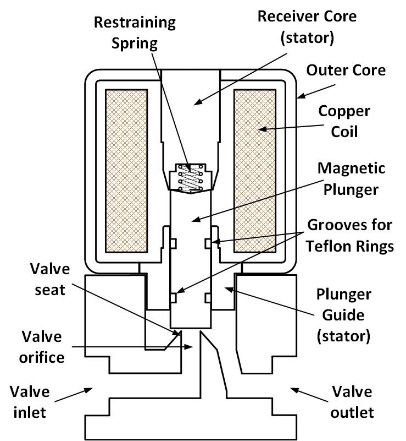
Proportional valves have the following functional components: a solenoid that produces a variable magnetic field when excited by a variable Direct Current (DC), a magnetic core that provides a low reluctance path for the magnetic field, a magnetic plunger that moves when the solenoid is excited, a valve body with a valve closure mechanism that is actuated by the solenoid and a spring that helps to keep the valve closed when the solenoid is unexcited.
The cylindrical plunger inside the hollow stator core moves towards the stator receiver core that has a tapered cross section at the inner end in the axial direction [1], [2], [4]. Two circumferential grooves are provided on the plunger at suitable locations to accommodate two Teflon rings [1] to reduce the friction between the metal plunger and the plunger guide.
Specifications of proportional solenoid valves include maximum flow rate, rated pressure and power. Design of the solenoid involves winding design, core material selection and optimization of the proportional core geometry, while that of valve involves the design of orifice and valve seat.
2.1. Winding Design
The winding of the proportional solenoid, is designed in such a way that it produces the required flux to generate force that is sufficient to create displacement of the plunger and the opening of the valve. As the proportional solenoid does not latch during its operation unlike an ON/OFF solenoid, it is important to ensure that the attractive force between the plunger and the stator is sufficient and moderated throughout its entire stroke length.
The power consumed by the solenoid is calculated as
P = I2R (or) VI (watt) (1)
where,
I – Solenoid Current (A)
R – Resistance of the solenoid (Ω)
V – Voltage across the solenoid (V)
Force produced by the solenoid on the plunger[1], [9]
$$\mathbf{F} = \frac{(NI)_g^2 \mu_0 A_g}{2g^2} \tag{2}$$
where,
(NI)g – Ampere turns required (A)
μ0 – Magnetic permeability of free space or vacuum (H/m) or (N/A2)
Ag – Area of the plunger surface (m2)
g – Length of the air gap (m)
$$8 = \frac{(NI)_g^2 \cdot 4\pi \times 10^{-7} \cdot \pi \cdot (5.5 \times 10^{-3})^2}{2 \cdot (1 \times 10^{-3})^2}$$
$$(NI)_g = \sqrt{\frac{8 \cdot 2 \cdot (1 \times 10^{-3})^2}{4\pi \times 10^{-7} \cdot \pi \cdot (5.5 \times 10^{-3})^2}}$$
$$(NI)_g = 366 \text{ ampere turns (AT)}$$
Magnetic field intensity across the air gap
$$H_g = \frac{(NI)_g}{g} \tag{3}$$
$$= \frac{366}{1 \times 10^{-3}}$$
$$H_g = 366 \times 10^3 \, \text{A/m}$$
Magnetic Flux density in the air gap,
$$B_g = \mu_0 \cdot H_g \tag{4}$$
$$= 4\pi \times 10^{-7} \cdot 366 \times 10^3$$
$$B_g = 0.46 \, \text{tesla (or) weber/sq. meter}$$
Total flux in the air gap,
$$\varphi_g = B_g \cdot A_g \tag{5}$$
$$= 0.46 \cdot \pi \cdot (5.5 \times 10^{-3})^2$$
$$\varphi_g = 43.7 \, \text{weber}$$
To produce the same flux throughout a magnetic core of same area Ag and a length of 200 mm:
Ignoring the fringing effect, the flux density in the core Bc = Bg = 0.46 tesla
Magnetic field intensity across the core
$$H_c = \frac{B_c}{\mu_c} \tag{6}$$
$$= \frac{0.46}{1000 \cdot 4\pi \times 10^{-7}}$$
$$H_c = 366.1 \, \text{A/m}$$
MMF required
$$(NI)_c = H_c \cdot \text{length} \tag{7}$$
$$= 366.1 \cdot 200 \times 10^{-3}$$
$$(NI)_c = 73.2 \, \text{AT}$$
Total Ampere turns required:
$$(NI)_{\text{total}} = (NI)_c + (NI)_g \tag{8}$$
$$= 73.2 + 366$$
$$(NI)_{\text{total}} = 439.2 \, \text{AT}$$
Considering additional 25 % for losses,
(NI)total=549 AT
Having a control current of 0.2 A (or) 200 mA would require number of turns
$$N = \frac{549}{0.2} \tag{9}$$
$$N = 2745 \, \text{turns}$$
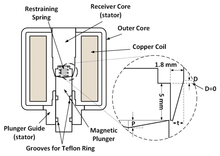
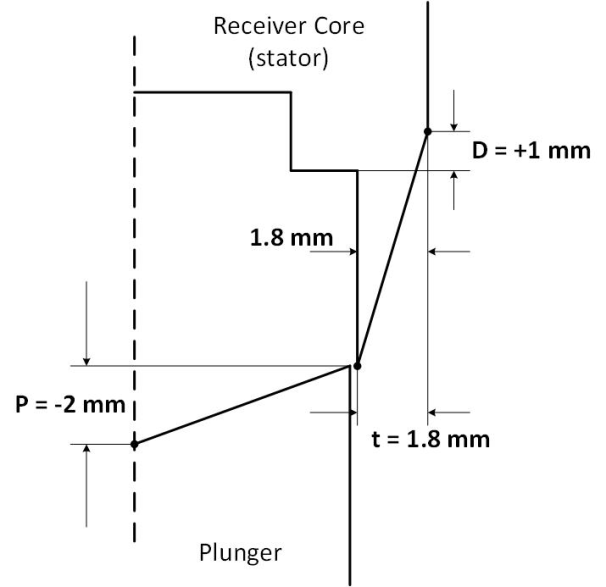
2.2. Geometry of the Magnetic Core
Proportional solenoids are required to produce a constant force throughout its full stroke length for a constant current. The geometry of the central core and the plunger of the solenoid plays a crucial role in achieving this. Figure 2 shows the cross-sectional geometry of the proportional solenoid with the control parameter D, t and P that have to be optimized for the solenoid to exhibit linearity and repeatability of the control movements of the plunger [2]. D represents the corner point on the outer edge of the cone, t represents the corner point on the top of the cone and P represents the depth of the conical top of the plunger.
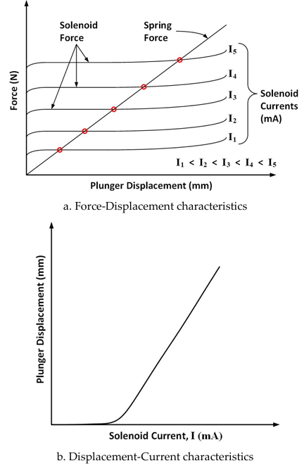
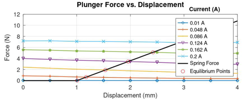
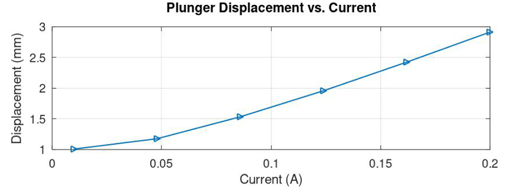
The typical Force-Displacement characteristic of a proportional solenoid is shown in Figure 3 (a). Ideally, the solenoid exhibits a constant force for a constant current for plunger displacement throughout the stroke length [3], [6]. This force increases proportional to the solenoid current. The restraining spring placed between the plunger and the receiver core produces a linear force with slope proportional to the spring constant. The intersections of the spring force with the solenoid force curves are the equilibrium points to which the plunger moves for various values of current through the solenoid [2], [6]. This in turn yields the relationship between the solenoid current and the plunger displacement as shown in Figure 3 (b).
3. Recursive Optimization of the Control Cone
Optimization of the control cone parameters such as D, t, and P is important to achieve consistent linear characteristics of the plunger movement with respect to the control input given to the solenoid. Analysis of various designs for the computation of force on the plunger is performed by Finite Element Method Magnetics (FEMM) software application [2], [7], [10] The details of mesh settings are as shown below
- Mesh Type: Triangular Mesh
- Mesh Size: Adaptive
Recursive method provides a simple approach towards optimizing the design parameters and also requires only two iterations in arriving at the optimum results. Even though design of proportional solenoids with different configurations is possible with multiple parameters that can be optimized, the given solenoid is designed with the configuration as shown in Fig 2, and optimized for the three independent variables namely D, t and P. Each step in the recursive method finds the optimal location of an individual parameter in coarse search that narrows down to a fine search in the subsequent iterations.
The optimization of the cone parameters of the proportional solenoid is based on minimizing the objective function f(s) [2], [6], [10] shown below:
$$f(s) = \sqrt{\frac{\sum_{n=1}^{x} \left( F(n) – F_{\text{avg}} \right)}{x}} \tag{10}$$
where,
f(s) – Objective function (N)
x – Number of plunger steps
F(n) – Force on plunger on nth step (N)
Favg – Average force on plunger across the full stroke length (N)
3.1. First iteration
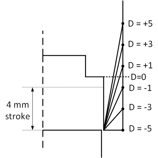
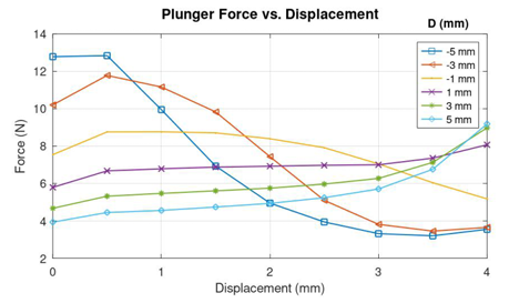
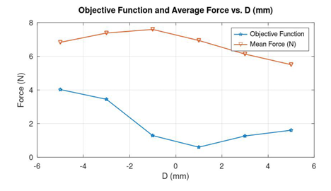
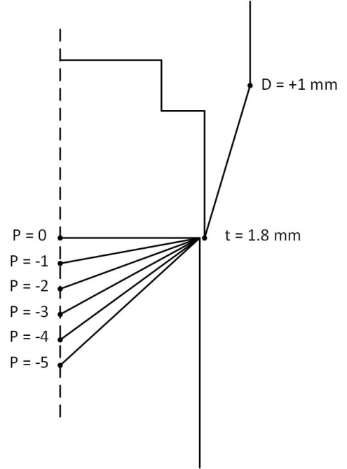
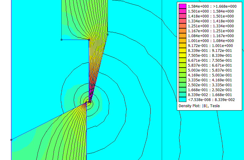
Every iteration in the optimization of the proportional solenoid geometry by recursive algorithm is a sequence of multiple steps of finding the near optimal value of the parameters, one at a step, in the order D, t and P. For each position of D at equal intervals between the constraints of -5 mm to +5 mm as shown in Figure 4, the plunger is moved for a stroke length of 4 mm from the tip of the cone with a step size of 0.5 mm to obtain the Force vs Displacement curves. The Force vs Displacement curves for various positions of D is shown in Figure 5. Having the corner point D near -5 mm show high force near the tip of the stationary core due to wide area made available by virtue of the position of D, which then reduces when the plunger moves deep inside the core due to increased area of low reluctance core appearing in the radial direction rather than axial. As the point D moves upwards making the shape of the receiver cone sharp and conical, the force on the plunger across its full stroke becomes moderate. It could be seen in Figure 6 that the values of the objective function are high for extreme values of D, which reduces to a lowest value of around 0.6 when D is at 1 mm above the reference point.
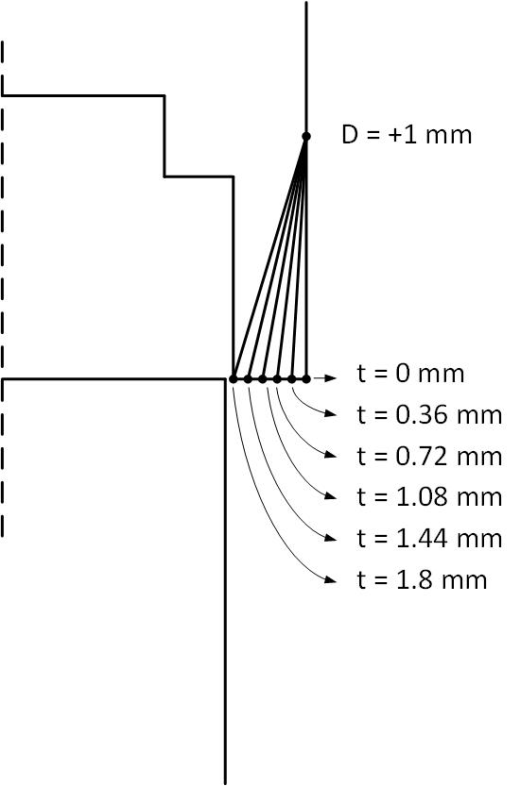
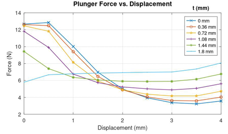
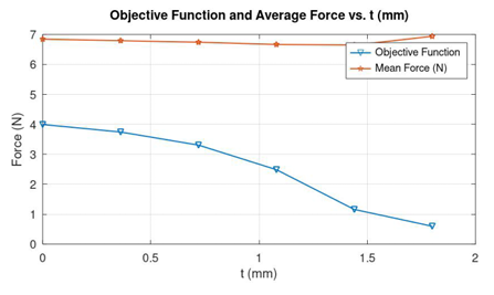
The optimal value of D = 1 mm obtained from the previous step is fixed for the optimization of t between the constrains of 0 mm to 1.8 mm in the next recursive step. With D = 1 mm, the position of t is varied from 0 to 1.8 in steps of 0.36 mm as shown in Figure 7. From the various Force vs Plunger Displacement curves in Figure 8, it could be seen that that the curve corresponding to t=1.8 appears to be flatter than the other curves. Figure 9 shows that the Objective function is also minimum for the same position of t, which is 1.8 mm.
The positions of D and t are fixed at 1 mm and 1.8 mm respectively from their references and the parameter P is next optimized.
Point P is at the axis of the cylindrical plunger and therefore moving P within the cylindrical structure of the plunger would create a hollow conical structure on the surface of the plunger facing the receiver core. Figure 10 shows the variation of P from -5 mm to 0 mm in 1 mm steps.
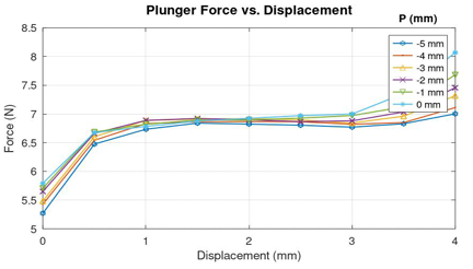
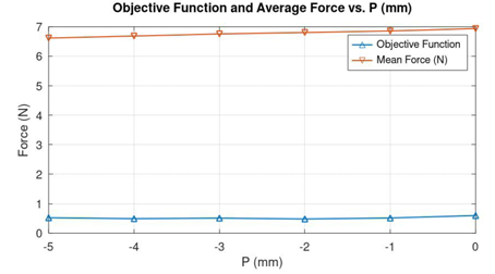
The force characteristics for various positions of P can be seen in Figure 11 and the objective function characteristics in Figure 12. The optimization of P would have considerable impact in reducing the latching tendency of the plunger when it moves closer towards the stationary receiver core beyond 3.5 mm.
The summary of parameters, constraints and the optimization results from the first iteration of the recursive method is shown in TABLE 1. The geometry obtained at the end of the First iteration is shown in Figure 13.
Table 1: Optimization results obtained from the First Iteration of the recursive method
Parameter | Min | Max | Step size (mm) | Optimal | Min. F(s) | Average force at Min. F(s) |
D | -5 | 5 | 2 | 1 | 0.59828 | 6.9384 |
t | 0 | 1.8 | 0.36 | 1.8 | 0.59828 | 6.9384 |
P | -5 | 0 | 1 | -2 | 0.48351 | 6.8065 |
3.2. Second Iteration
The first iteration of the recursive method has given a rough idea of the optimal locations of the geometrical parameters. A second iteration is essentially required to obtain accurate results of the optimization parameters. TABLE 2 shows the details of the new parameter constraints, optimal values and the corresponding objective function. The new parameter constraints with narrow step sizes are set near the previously obtained optimal results in such a way that a detailed search is performed for finding the accurate locations of the parameters. It could be seen that the value of Minimal Objective Function has reduced from around 0.59 to 0.15 from the first row of TABLE 1 to the last row of table 2.
Table 2: Optimization results obtained from the Second Iteration of the recursive method
Parameter | Min | Max | Step size (mm) | Optimal | Min. F(s) | Average force at Min. F(s) |
D | 0 | 2 | 0.4 | 0.4 | 0.40518 | 7.131 |
t | 1.3 | 1.8 | 0.1 | 1.7 | 0.18655 | 6.9748 |
P | -3 | -1 | 0.2 | -1 | 0.14875 | 7.0161 |
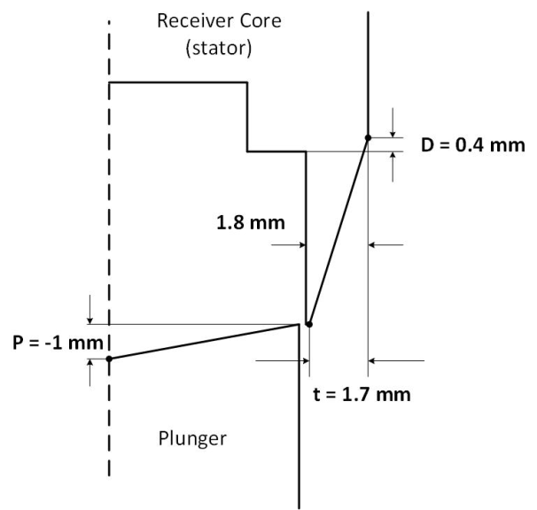
Figure 14 to Figure 19 show the force curves and the objective function curves obtained during the second iteration in the recursive optimization of D, t and P. The optimal values of the parameters are obtained as P = + 0.4 mm, t = + 1.7 mm and P = -1 mm. The optimal geometry of the proportional core of the solenoid is shown in Figure 20.
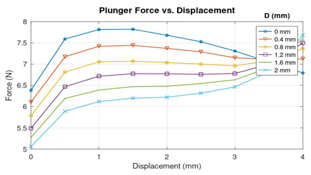
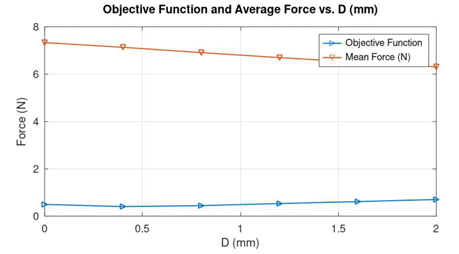
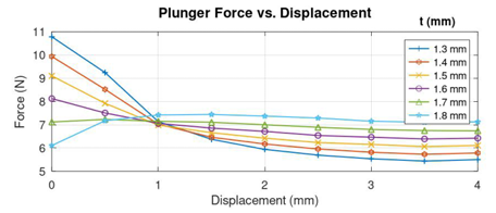
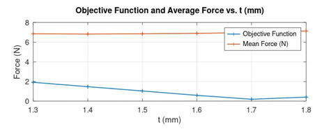
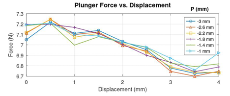
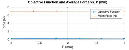
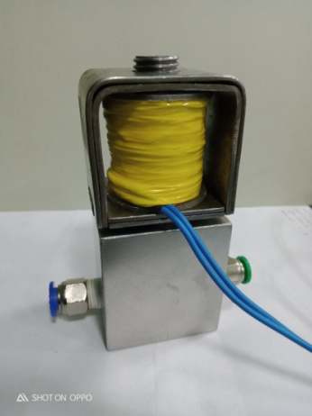
Figure 21 shows the proportional solenoid valve that is developed with the optimized core geometry for gas flow at a maximum pressure of 3 Bar.
4. Performance testing and results
The optimized geometry of the proportional solenoid has to be checked for its optimal performance. Optimization of the proportional solenoid geometry has helped to achieve constant force for constant current through the solenoid winding regardless of the position of the plunger within the span of the 4 mm stroke length where the solenoid is intended to operate.
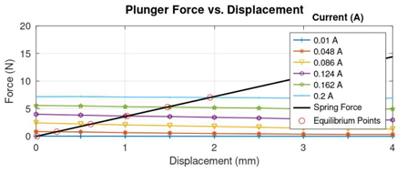
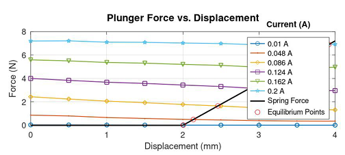
Force curves of the optimized solenoid for various values of constant currents and the force generated by the restraining compression-spring with a spring constant of 3.6 N/mm represented as the load line are shown in Figure 23.
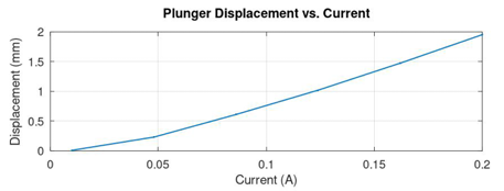
The intersections between the load line and the force curves are obtained and the characteristics between solenoid current and the plunger displacement is drawn as shown in Figure 24.
For an optimized proportional solenoid, the relationship between the control current and the plunger displacement remains same in the stroke length of the plunger regardless of the initial offset of the spring or the initial position of the plunger.
The load line of the spring that is offset by 1 mm along with the force curves of the proportional solenoid is shown in Figure 25. The characteristics between the control current of the solenoid and the plunger displacement is shown in Figure 26. It may be noted that the displacement of the plunger starts from the initial offset position of the spring at 1 mm.
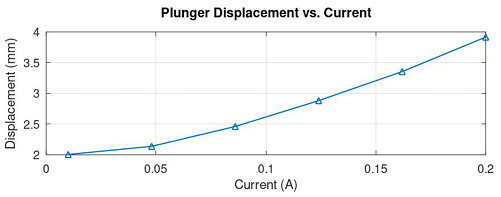
The load line of the spring that is offset by 2 mm along with the force curves of the proportional solenoid is shown in Figure 27. The characteristics between the control current of the solenoid and the plunger displacement is shown in Figure 28. It may be noted that the displacement of the plunger starts from the initial offset position of the spring at 2 mm.
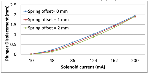
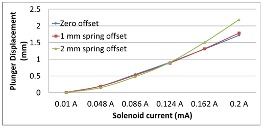
The effective displacement of the plunger in the optimized model of the proportional solenoid with three different offsets such as 0 mm, 1 mm and 2 mm is shown in Figure 29. It can be seen that the characteristics are close to each other. It should be noted that the desirable ideal characteristics is to have all curves straight and aligned with each other.
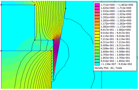
For a non-optimal design, the control characteristics may not be straight and aligned as it may be expected. Figure 30 and Figure 32 show two non-optimal designs featuring flatter than optimal design and sharper than the optimal design respectively.
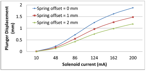
The characteristics of the two non-optimal designs are shown in Figure 31 and Figure 33. An undesirable widening in characteristics can be seen in Figure 31 corresponding to a flat non-optimal geometry. It can be seen in Figure 33 that two of the curves are close to each other with lesser displacement than optimal and the third curve is deviating.
The Plunger displacement vs current characteristics is experimentally obtained from the manufactured proportional solenoid and compared with the computed characteristic of the optimized geometry as shown in Fig 34.
Having the objective of achieving an optimized geometry of proportional solenoid to produce linear displacement for coil currents regardless of the initial offset, the experimental displacements from initial offsets of 0 mm, 1 mm and 2 mm are compared with the corresponding computed displacements as shown in Figure 34.
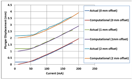
The graphs show close agreement between actual and computed values, which validates the proposed optimization method based on recursive technique. The actual displacement with 0 mm offset is slightly lower than the computational displacement due to the plunger being near the far end of the proportional cone. With increased offset, i.e., when the plunger position is well inside the proportional cone, the force on plunger tends to be higher resulting in higher displacement. However, still higher offsets would result in the displacement getting flattened when the plunger goes too much inside the proportional cone due to the flux in the air gap becoming more lateral than axial.
5. Conclusion
This paper has presented the technical approach to the development of a proportional solenoid valve. The basic operation of the proportional solenoid, selection of materials, power supply related design approaches have been discussed. Optimization of the proportional core, being one of the crucial steps in the design of a proportional solenoid has been given primary focus in this report. The recursive method of optimization is used for the finding the best geometry of the proportional core of the solenoid valve due to its effective approach in yielding the optimization results in less than three iterations. The step by step process of optimization of the geometrical parameters of the proportional core is illustrated with diagrams and graphs. A hardware version of the proportional solenoid valve based on the optimal design is manufactured and tested for its performance. The results show that the proportional solenoid optimized using the proposed technique of recursive method exhibited linear displacement for the solenoid current for various offsets. The design approach illustrated in this technical report can be utilized for manufacturing proportional solenoid valves suitable for a variety of applications.
Conflict of Interest
The authors declare no conflict of interest.
Acknowledgment
This work is supported by the Central Manufacturing Technology Institute, Bengaluru, India-560022.
- S.J. Wang, et al., “Multi-objective genetic algorithm optimization of linear proportional solenoid actuator”, J Braz. Soc. Mech. Sci. Eng. vol. 43, no. 60, 2021, doi.org/10.1007/s40430-020-02768-7.
- S.N. Yun et al., “New approach to design control cone for electro-magnetic proportional solenoid actuator”, IEEE/ASME International Conference on Advanced Intelligent Mechatronics (AIM), 2012, doi: 10.1109/AIM.2012.6265943.
- S. Wu et al., “Multiobjective Optimization of a Hollow Plunger Type Solenoid for High Speed On/Off Valve”, IEEE Transactions on Industrial Electronics, vol. 65, no. 4, pp. 3115–3124, 2018, doi: 10.1109/TIE.2017.2756578.
- F. Meng et al., “System Modeling, Coupling Analysis, and Experimental Validation of a Proportional Pressure Valve WithPulse width Modulation Control”, IEEE/ASME Transactions on Mechatronics, vol. 21 no. 3, pp. 1742–1753, 2016, doi: 10.1109/TMECH.2015.2499270.
- P.B. Lequesne, “Finite-element analysis of a constant-force solenoid for fluid flow control”, IEEE Transactions on Industry Applications, vol. 24, no. 4, pp. 574–581. 1988, https://doi.org/10.1109/28.6107.
- T. Arakawa, “Optimization Technology of Magnetic Circuit for Linear Solenoid”, SAE Technical Paper Series, 2002, https://doi.org/10.4271/2002-01-0565.
- Plavec, E., & Vidovic, M., “Genetic algorithm-based plunger shape optimization of DC solenoid electromagnetic actuator” 24th Telecommunications Forum (TELFOR), 2016, doi: 10.1109/TELFOR.2016.7818839
- Sang-Baeck Yoon, JinHur, Yon-Do Chun, & Dong-Seok Hyun, “Shape optimization of solenoid actuator using the finite element method and numerical optimization technique”, IEEE Transactions on Magnetics, vol 33, no 5, pp. 4140–4142, 1997, https://doi.org/10.1109/intmag.1997.597697
- Vogel, O., Ulm, J.,”Theory of Proportional Solenoids and Magnetic Force Calculation Using COMSOL Multiphysics”, Excerpt from the Proceedings of the COMSOL Conference, Stuttgart, 2011.
- Jae Seop Ryu, Yingying Yao, Chang Seop Koh, Sonam Yun, & Dong Soo Kim, “Optimal shape design of 3-D nonlinear electromagnetic devices using parameterized design sensitivity analysis”, IEEE Transactions on Magnetics,vol. 41, no. 5, pp. 1792–1795, 2005, doi 10.1109/TMAG.2005.845982