Studies on Stress Analysis of Hip Prosthesis Implant
(This article belongs to the Section Biomedical Engineering (BIE))
Export Citations
Cite
Wani, C. M. , Deshmukh, S. R. and Ghorpade, R. R. (2022). Studies on Stress Analysis of Hip Prosthesis Implant. Journal of Engineering Research and Sciences, 1(8), 1–11. https://doi.org/10.55708/js0108001
Chetan Mohanlal Wani, Sachin Ratnakar Deshmukh and Ratnakar Raghunath Ghorpade. "Studies on Stress Analysis of Hip Prosthesis Implant." Journal of Engineering Research and Sciences 1, no. 8 (August 2022): 1–11. https://doi.org/10.55708/js0108001
C.M. Wani, S.R. Deshmukh and R.R. Ghorpade, "Studies on Stress Analysis of Hip Prosthesis Implant," Journal of Engineering Research and Sciences, vol. 1, no. 8, pp. 1–11, Aug. 2022, doi: 10.55708/js0108001.
Biomedical engineering has become a solution for many biological problems by the application of principles and problem-solving techniques. Pacemakers, artificial bone replacements, 3-D printed organs, and dental replacements are very common examples of an application of engineering in the biomedical field. In medical applications when there is a need for bone replacement in a patient who is suffering from arthritis, the hip joint replacement cannot be avoided. The use of the artificial hip joint is going more popular and has become a need in the case of arthritis. An artificial hip implant is essential for providing initial stability at the place of failure. The comparative study in this field is limited and needs to be studied thoroughly. This paper focuses on a comparative study of hip replacement implants using SS (stainless steel) and Ti6Al4V (titanium alloy). In this study, 3-dimensional finite element analysis (using ANSYS2020) of hip replacement implant is performed by applying directional loads to detect von-mises stress amount, stress locations, and deformation in the implant. Assembly of the hip replacement implant is modeled (using Fusion 360) and static structural analysis is separately done using two different materials (SS and Ti-6Al-4V) for the femoral stem and using HDPE and HDPE/0.25MWCNT/0.15 for acetabular cup and liners respectively. Boundary conditions and loads applied are unchanged while varying parameters are the neck angle of implant and materials used. A similar static structural analysis for the elevated liner and flat liner at three different shell inclinations is done separately using the model which has shown better results. This study will help the researchers for further study on stress analysis of hip prosthesis implants.
1. Introduction
The human body has roughly 270 bones when it is born, but by adulthood, it has been lowered to 206 bones since some of the bones have bonded together [1]. The femur seems to be the longest and also highest load-carrying bone in the human body, joining the pelvic in the proximal and the tibia in the distal. Its length fluctuates from individual accounts for around a quarter of the body’s height (45–50 cm in general) [2]. In the human body, the hip joint is considered one of the most critical joints. Knee and total hip surgeries are universally acknowledged as efficient and positive treatments for osteoarthritis of the joint [3]. Total hip arthroplasty (THA) is the medical term intended for hip replacement. Year after year, the total number of hip replacement operations is rising [4]. More effort has been made to satisfy the patient’s isolated requirements, for example by increasing the range of types and sizes of hip prostheses, a large proportion of THAs become loose after they have been implanted for decades [5]. This joint can decay due to numerous reasons that include osteoarthritis, atrophic arthritis, and avascular necrosis [6]. Stem or head rupture, wear and eventual metallosis illnesses, destabilization owing to bone breakage, necrosis or stress shielding, and infectious agents that develop a biofilm between of implant and the bone are all reasons for implant failure [7]. Strain and stress shielding, as results from the differing rigidity of implant materials and the neighboring bone, is a major concern with hip resurfacing arthroplasty (HRA) [8]. Aseptic loosening of the acetabulum due to stress shielding and altered load distribution within the adjacent bone structure is a common cause of total hip arthroplasty failure [9]. Studies projected that, worldwide, there are nearly one million surgeries of hip replacement done every year [10]. Implants are generally selected based on the patient’s age and bone condition; for older patients, cemented implants are often favored. 2D radiography or preoperative 3D planning tools ensure that the implant and the femur are geometrically compatible [11]. In various actions, the hip joint can carry an upper body weight of up to four times that of the human body weight.
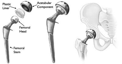
An artificial hip implant is consisting of mainly two components. First is the acetabular element which is placed in the pelvis and the second is a femoral element which includes a femoral stem and ball-like head placing the femoral head. The geometry of the hip replacement implant is shown in figure 1.1. In healthful individuals, the skeletal interaction regions are coated by articular cartilage, a soft and delicate tissue that cushions the endpoints of the pelvis and femur bones and then almost eliminates friction. The Tissue bands hold the ball and joint together [12]. A large proportion of THAs experience loosening after 15-20 years of implantation. Approximately 30% of patients that have undergone total hip replacement need revision of operation [5].
There is proof that adopting bigger femoral head sizes and increased offsets lessen the chance of hip unnecessary displacement by permitting more impingement-free mobility and thereby enhancing the jumping range in both initial and repair unrestricted THA [13].
Yekutiel Katz et al. performed Ex-Vivo tests on four fresh-frozen human femurs and found that the finite element models relying on computed tomography can accurately calculate strains on the femur surfaces and implanted implants at the cement interface [11]. Kaddick et al. investigated static failure loads and peak stresses of physiologically formed carbon fiber reinforced epoxy hip stem using finite-element analysis. At the same forces, they found that flexible implants create larger strains than stiffer implants [14]. Kayabasi and Ekici investigated the impacts of stable, dynamical, and fatigue behavior on three-dimensional shape optimization of titanium and cobalt-chromium alloy hip prostheses using PMMA cemented in the casual walking scenario using the FE approach. They discovered that whereas stem designs are projected to be safe against failure under static stress, collapse can occur during dynamical repetitive loading [15].
Materials used for hip prosthesis implants are studied in detail In this paper. Broadly used materials for the hip joint implant can be distributed into several pairs: polymer to ceramic, metal to metal, metal to polymer, and ceramic to ceramic [16]. The most widely used metals for stem and femoral heads are stainless steel, Ti alloy, and Cr-Co alloy. Polymers are used for the acetabular liner and polymers, composites, or bio metals are used for the acetabular shell. Each material has its advantages and disadvantages. Some of the properties that are considered during the selection of materials are their yield strength, density, young’s modulus, hardness, corrosion resistance, biocompatibility, and biodegradability. Further chapters discuss the CAD design, analysis, results, and conclusion for the analysis done on hip prosthesis implant.
2. Materials
The materials are selected by considering the human biological environment and by considering the mechanical properties of the human hip bone. The mechanical properties of human bone are shown in table 1.
Table 1: Mechanical properties of human bone
Density (Kg/m3) | Yield Strength (Pa) | Poisson’s Ratio | Young’s Modulus (Pa) |
310±60 | 1.14e+8 | 0.62±0.26 | 1.1e+10 – 2e+10 |
There are two primary criteria for selecting materials. Medical requirements are concerned with the material’s biocompatibility, while mechanical criteria are concerned with wear resistance, stress concentration, and implant stability [17].
2.1. Ti6Al4V
Ti6Al4V is the most commonly used titanium alloy, making up about half of all titanium options on the market today [18]. Because titanium and titanium alloys are biodegradable, they do not require an intermediary layer of cement-like stainless steel or CrCo alloys. Due to the lower shear resistance, Ti and Ti alloys are wear-resistant [16]. The two Ti-based alloys now accessible for implantation are commercially sterling titanium and Ti–6Al–4V, though Ti-6Al-V4 is taking over commercially sterling titanium because of its superior mechanical strength. Long-term application of Ti alloys causes health issues like Alzheimer’s disease and neuropathy, which are mostly driven by aluminum and vanadium excretion [16].
2.2. Polymers
Due to their minimal price and a broad variety of physical and mechanical qualities, polymer materials are utilized in a wide range of uses. Polymers are categorized into two categories depending on how far they last in biological atmospheres:
- Biodegradable and 2. Biostable Polyethylene (PE), poly (methylmethacrylate) (PMMA), and polyetheretherketone (PEEK) are examples of biostable polymers that are used in hip and dental implants [16]. For hip and knee joints, UHMWPE (ultrahigh molecular weight polyethylene) has been widely employed [16]. Polylactic acid (PLA), polyglycolic acid (PGA), poly lactic-co-glycolic acid (PLGA), and poly e-caprolactone (PCL) are the second family of biodegradable polymers that can break down gradually in the body’s physiological milieu into biocompatible compounds [16]. The early study exposed that UHMWPE is an appropriate material for THR.
2.3. Stainless Steel
Because of its high Cr content (more than 12 wt %), Materials made of stainless steel are more resistant to a wide range of eroding environments, allowing for the creation of a firmly adhering, corrosion-resistant, and self-curing Cr Cr2O3 coating oxide. The formation of chromium carbides at grain borders does not induce intergranular corrosion in austenitic stainless steel [19]. SS has few applications in medical implants, despite its many benefits as in a presence of chloride, it is susceptible to corroding, leading to the release of harmful metallic ions like chromium and nickel [20]. Implants made of stainless steel have degraded in the body because of pitting, crevice corrosion, corrosion fatigue, fretting corrosion, stress corrosion cracking, and galvanic corrosion, despite these properties [16]. Because chromium in the outermost layer interacts with oxygen, a thin film of adhered and cohesive oxide (passive film) encloses the surface and acts as a rusting barrier [19]. The withstanding ability of austenitic stainless steel with wear is quite low. Sterile slackening of the joint occurs when a large amount of worn fragments is formed. Furthermore, stainless steel has a modulus of roughly 200 GPa, which is significantly more than bone [16] having a modulus in the range of 11-20 GPa. Materials and their properties considered in this study are [21], [22]:
Table 2: Materials and properties used
Materials | Density (Kg/m3) | Yield Strength (Pa) | Poisson’s Ratio | Young’s Modulus (Pa) |
Ti-6Al-4V | 430 | 8.8E+08 | 0.28 | 1.09E+11 |
HDPE | 964 | 2.97E+07 | 0.42 | 1E+15 |
HDPE/0.25 MWCNT/0.15 | 964 | 4.2E+07 | 0.43 | 1.5E+09 |
Stainless Steel | 8000 | 2.15E+08 | 0.27 | 2.1E+11 |
- Acetabular shell: HDPE
- Liner: HDPE/0.25MWCNT/0.15
- Femoral head: Ti6Al4V/Stainless steel
- Femoral stem: Ti6Al4V/Stainless steel
3. Methodology
3.1. Design
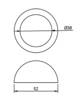
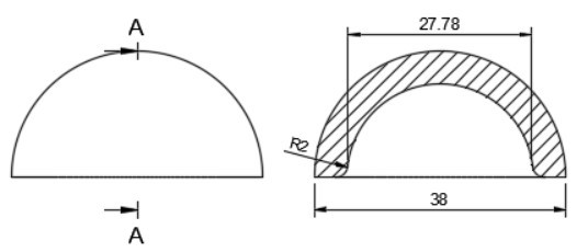
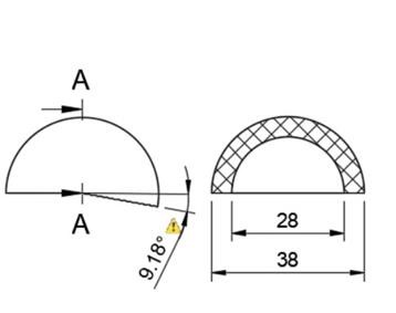
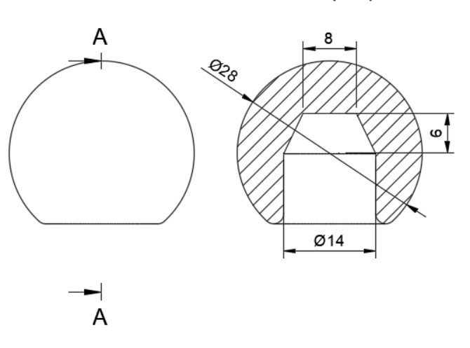
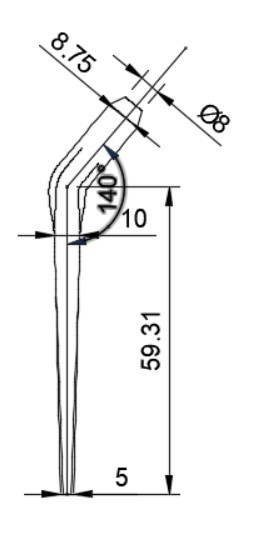
In total hip arthroplasty, a variety of designs are routinely employed. Profile and shape are significant parameters at design time distortion [23]. In this study, the total assembly of an artificial hip implant is divided into four components that are 1] Acetabular shell 2] Acetabular liner (flat/elevated at 10°) 3] Femoral head 4] Femoral stem. The design and assembly are done in the Fusion 360 software. Acetabular shell has an outside diameter of 52 mm and an inside diameter of 38 mm, an outer diameter of both flat and elevated liner is considered as 28 mm and outer diameter as 38 mm, the elevation of the elevated liner is kept as 10° [21]. The diameter of the femoral head is 28 mm, and the length of the femoral stem is taken as 120 mm [22]. Even across smaller group measurements, the angle of the femoral neck concerning the shaft (the neck-shaft angle, NSA) varies greatly between contemporary humans and previous hominins. Adult figures for modern humans are typically within the range of 120 and 140 degrees, while readings as low as 120 degrees and as high as 140 degrees are not unusual (known as coxa varus and coxa valgus, respectively). [24]. As per the studies by Ian Gilligan [24], NSA varies from 115°-140° (range of 25° in 47 Indian samples, σ= 5, mean= 129.9°). So, different assemblies were done by changing the neck angle by 120°, 130°, and 140° [22]. Dimensions for the design are taken from [21]. The assembly file is then exported into .iges format for further analysis.
More detailed dimensions of the CAD model are given in following figure 2 (a-e):
3.2. Finite Element Analysis
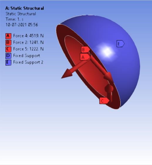
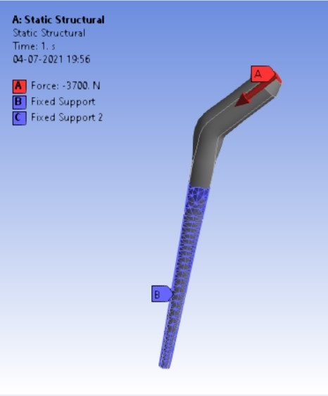
The finite element method is a commonly used method of computer technology for dental implant research [25]. Biomechanical characteristics of the implant-bone compound are a strain/stress distribution that may be important in selecting the best implant [11]. Finite element analyses (FEA) may now provide this biomechanical knowledge by identifying the implant that generates the least divergence in the strain distribution relative to the strain distribution before the breakage of a bone [11]. These methods are widely employed in the fields of autos, aeronautics, as well as various structural and fluid dynamic applications to solve multi-physics difficulties [26]. On the spot, a computer simulation was performed. ‘ANSYS Workbench 2020’ platform is used for finite element analysis in this study. The materials which are to be used in the analysis were added and the properties for each material were provided along with their values. The materials were assigned for each component in the assembly i.e. HDPE for acetabular cup, HDPE/0.25MWCNT/0.15BNNP for acetabular liners (flat and elevated), stainless steel, and Ti6Al4V assigned to femoral stem and head. For every iteration, the material is chanfromd from stainless steel to Ti6Al4V. After assigning materials, 3 contact regions were provided as bonded for cup and liner, frictional between head and liner by providing frictional coefficient as 0, again bonded contact were provided to the stem and head. The next step was dividing the complete assembling into small elements by meshing. A tetrahedron mesh was used as the mesh element with a mesh size of 2 mm. Tetrahedron mesh is used because it discretizes the complex geometries better in equal parts and a size of 2 mm was provided for fine meshing. The boundary conditions [22] were provided to the assembly model. Boundary conditions were kept unchanged for the analysis of each assembly model. Total 4-point loads were applied. One load of 3700 N in the reversed direction was on the top surface of the stem the and other 3 loads were applied on the inner surface of the shell on the X, Y, and Z-axis having values of 1241 N, -4519 N, and 1222 N respectively as shown in following figure 3 (a,b):
After applying boundary conditions, solutions that are needed to find were added to the list of solutions.
4. Results and Discussion
After the analysis in static structural, results were calculated in the form of von-mises stresses induced in MPa and the total deformation generated in mm in each assembly model of hip prosthesis implant. The following figures show the results:
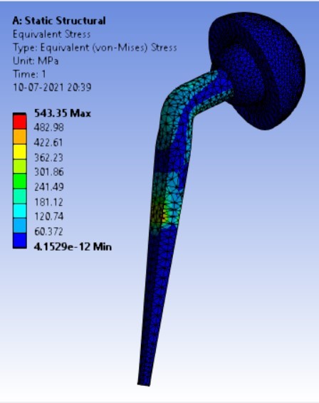
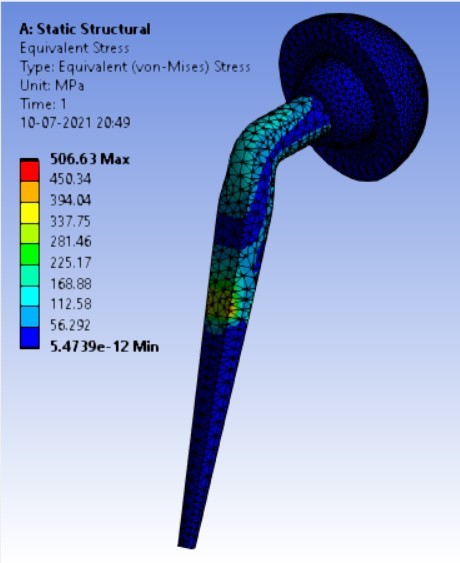
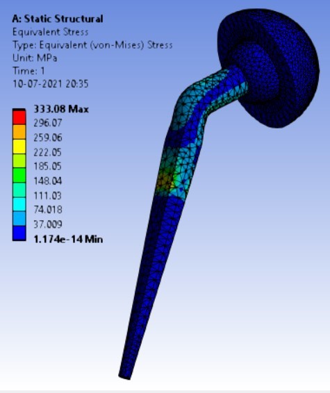
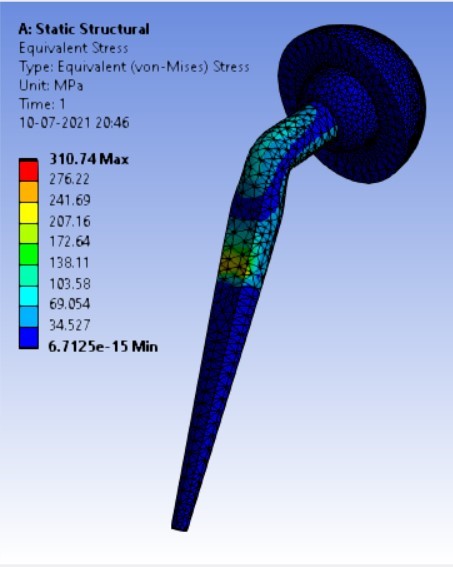
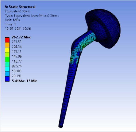
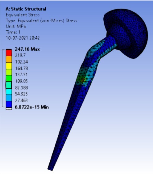
Von-mises stress for different neck angle angles [figure 4 (a-f)]:
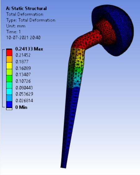
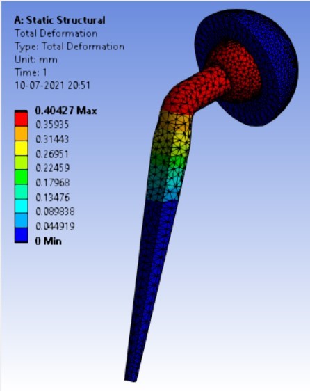
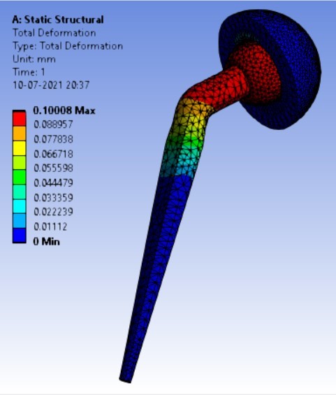
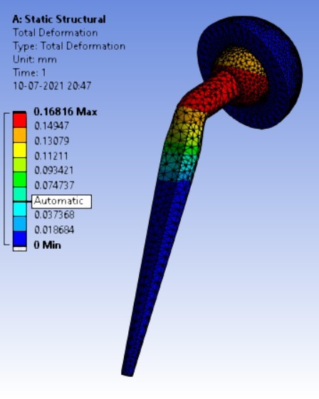
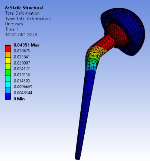
Displacement for different neck angle-angle [figure 5 (a-f)]:

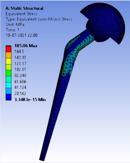
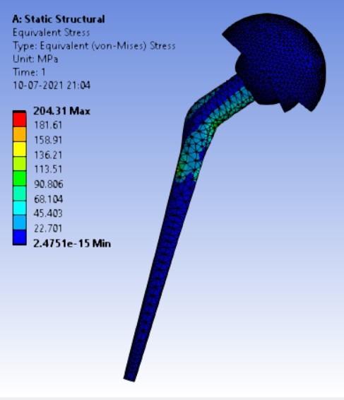
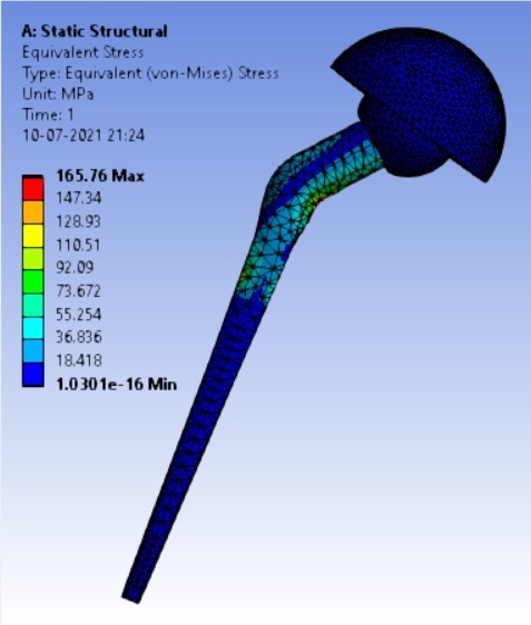
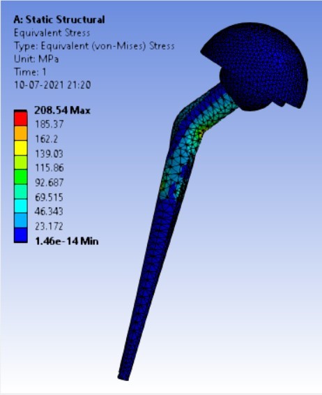
Von-mises stress for the different inclination of the shell using flat and elevated liner [figure 6 (a-f)]:


Displacement for the different inclination of the shell using flat and elevated liner [figure 7 (a-f)]:
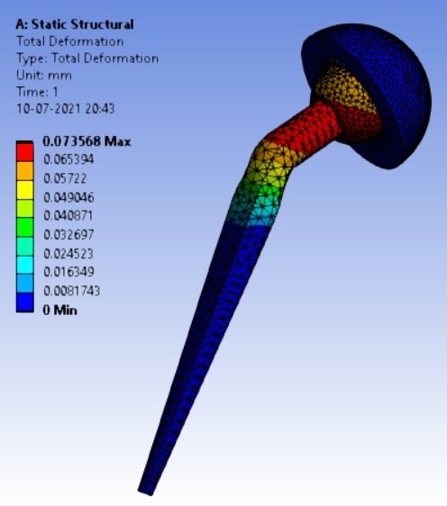
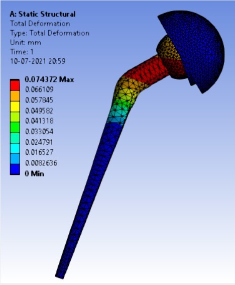
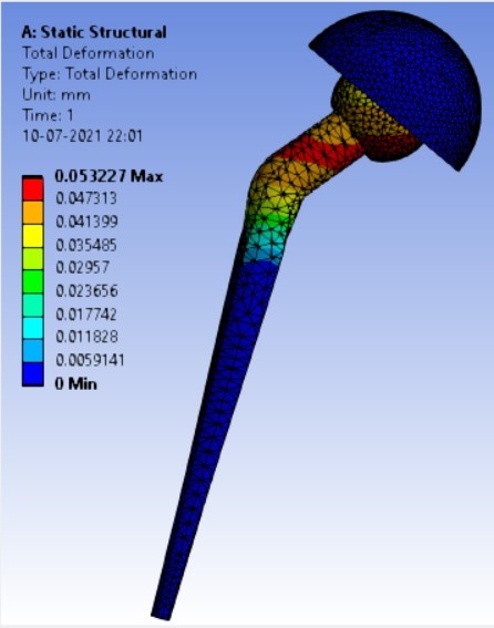
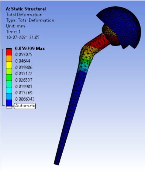
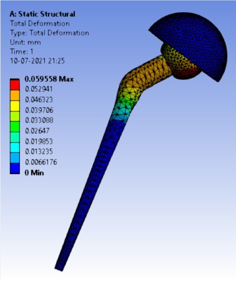
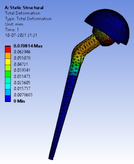
Table 3: Result table for different neck angle angle
Sr. No. | Variable Parameter (Stem angle ‘ø’) | Equivalent Stress (MPa) | Displacement (mm) | ||
Ti Alloy | Stainless Steel | Ti Alloy | Stainless Steel | ||
1. | 120° | 506.63 | 543.35 | 0.40427 | 0.24133 |
2. | 130° | 310.74 | 333.08 | 0.16816 | 0.10008 |
3. | 140° | 247.16 | 262.72 | 0.07357 | 0.04351 |
Table 4: Result table for different shell inclination
Sr. No. | NSA (neck-shaft angle) | Equivalent stress (MPa) | ||
Stress in stem from the studies done by Dannana Dimple et.al. [22] | Ti Alloy | Stainless Steel | ||
1. | 100° | 336 | – | – |
2. | 110° | 238.56 | – | – |
3. | 120° | 208.32 | 506.63 | 543.35 |
4. | 130° | 204.96 | 310.74 | 333.08 |
5. | 140° | 147.84 | 247.16 | 262.72 |
The results for all the equivalent stresses and displacements are given in table 3 & table 4. Figure 8 shows the graph of the influence of stem angle on the behavior of equivalent stress for SS and Ti6Al4V. Likewise, Figure 9 describes the graph for the influence of shell inclination on the behavior of equivalent stress.
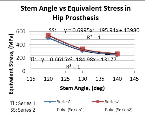
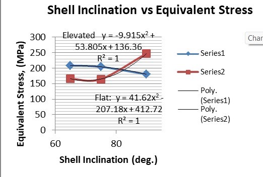
As the neck angle (ø) increases, the amount of equivalent stress is decreased. The maximum value of stress is at an angle of 120° in stainless steel i.e. 543.35 MPa and the minimum value of stress is at 140° in Ti alloy i.e. 247.16 MPa. The weight of stainless steel is more than that of Ti-6Al-4V. Also, in all the cases, more stress is observed in SS than stress observed in Ti-6Al-4V. As the inclination of the acetabular shell increases, assemblies that used elevated liners have increasing values of von-mises stress than the assemblies that used flatliners. From the results in this study, if we consider other properties of liners like the ability to provide support and motion stability, elevated liners used in assembly at an angle of 75° showed better results.
Table 5: Comparison of the results
Sr. No. | Variable Parameter (Inclination of shell) | Equivalent Stress (MPa) | Displacement (mm) | ||
Elevated | Flat | Elevated | Flat | ||
1. | 90° | 180.25 | 247.16 | 0.074372 | 0.07357 |
2. | 75° | 204.31 | 164.84 | 0.05971 | 0.05899 |
3. | 65° | 208.54 | 165.76 | 0.0708 | 0.05956 |
A comparison of the results from the studies done by Dannana Dimple et. al. and the results from this study are given in table 5. From both the studies it can be observed that, as the NSA is increased, the stresses generated showed decreasing values. It is observed in both the studies that stress amount at an NSA of 140° is the least. Study by Dannana Dimple et. al. is based on the FEA of stem separately unlike in the presented study, the FEA is done on whole assembly of hip implant.
5. Conclusion
If the ratio of displacement concerning stress is considered, stainless steel has shown better results than that of Ti6Al4V. That is, if the same amount of stress is considered in both materials, the displacement in stainless steel will have a lower amount than Ti6Al4V. Also, unlike stainless steel, Ti6Al4V is biodegradable and the stress generated in Ti6Al4V is less for the same boundary conditions, Ti6Al4V would be preferable over stainless steel. Ti6Al4V implant at an angle of 140° is preferable for surgeries where a 140° neck angle-angle is allowed. As the inclination of the acetabular shell increases, assemblies that used elevated liners have increasing values of von-mises stress than the assemblies that used flatliners. There is very little difference between the displacements of elevated and flatliners at each angle. As the surface contact area in elevated liners is larger than in flatliners, elevated liners provide support and more stability to the movement of the femoral head whereas flat liners provide less stress-affected area. Surgeons should take these properties under consideration before using the liners. From the results in this study, if we consider other properties of liners like the ability to provide support and motion stability, elevated liners used in assembly at an angle of 75° showed better results so, it is preferable for use in hip implants.
Conflict of Interest
The authors declare no conflict of interest.
- Chethan K. N., Shyamasunder Bhat N., Zuber M., Satish Shenoy B, “Finite Element Analysis of Different Hip Implant Designs along with Femur under Static Loading Conditions,” Biomed Phys Eng., pp. 507-516, 2019, doi:https://doi.org/10.31661/jbpe.v0i0.1210.
- Yunus E Delikanli, Mehmet C Kayacan, “Design, manufacture, and fatigue analysis of lightweight hip implants,” Journal of Applied Biomaterials and Fundamental Materials, pp. 1-19, May 2019, doi: 1177/2280800019836830.
- Kurtz, S., Mowat, F., Ong, K., Chan, N., Lau, E., and Halpern, “Prevalence of primary and revision total hip and knee arthroplasty in the United States from 1990 through 2002,” J. Bone Jt Surg. Am., 2005, 87A(7), 1487–1497.
- Kurtz, S., Ong, K., Lau, E., Mowat, F., and Halpern, M. “Projections of primary and revision hip and knee arthroplasty in the United States from 2005 to 2030,” J. Bone Jt Surg. Am, 89A(4), pp. 780–785, 2007, doi: 10.2106/JBJS.F.00222.
- X Li, D Li, Q Lian, H Guo, and Z Jin, “The effect of stem structure on stress distribution of a custom-made hip prosthesis,” Proceedings of the Institution of Mechanical Engineers Part H Journal of Engineering in Medicine, pp. 1-12, November 2010, doi:10.1243/09544119JEIM768.
- Rilo Berdin Taqriban, Rifky Ismail, J Jamari, A Priharyoto Bayuseno, “Finite element analysis of artificial hip joint implant made from stainless steel 316L,” Bali Medical Journal | Bali Medical Journal, pp. 448-452, 2021, doi:10.15562/bmj.v10i1.2236.
- Fiorentino, G. Zarattini, U. Pazzaglia, E. Ceretti, “Hip prosthesis design. Market analysis, new perspectives and an innovative solution,” Procedia CIRP 5, pp. 310 – 314, 2013, doi:10.1016/j.procir.2013.01.061.
- Danny Vogel, Merle Wehmeyer, Maeruan Kebbach, Horst Heyer, Rainer Bader, “ Stress and strain distribution in femoral heads for hip resurfacing arthroplasty with different materials: A finite element analysis,” Journal of the Mechanical Behavior of Biomedical Materials, pp. 1-11, 2021, doi:https://doi.org/10.1016/j.jmbbm.2020.104115.
- Danny Vogel, Matthias Klimek, Michael Saemann and Rainer Bader, “Influence of the Acetabular Cup Material on the Shell Deformation and Strain Distribution in the Adjacent Bone—A Finite Element Analysis,” Materials, pp. 1-16, 2020, doi:10.3390/ma13061372.
- Wilkinson, J. M., Peel, N. F. A., Elson, R. A., Stockley, I., and Eastell R. “Measuring the bone mineral density of the pelvis and proximal femur after total hip arthroplasty,” J. Bone Jt Surg. Br., 83B(2), pp. 283–288, 2001.
- Yekutiel Katza, Omri Lubovskyb, Zohar Yosibasha, “Patient-specific finite element analysis of femurs with cemented hip implants,” Clinical Biomechanics, pp. 1-32, 22, June 2018, doi :10.1016/j.clinbiomech.2018.06.012.
- M. Kamel, “Modeling And Simulation Of A Hip Prosthesis Implantation,” Proceedings of the 18 SM 27th Int. AMME Conference, 3-5, pp. 1-13, April 2018, doi:10.21608/AMME.2018.35024.
- Yaniv Warschawski, Simon P.Garceau, Denis A.Joly, Paul Kuzyk, Allan Gross, OlegSafir, “The Effect of Femoral Head Size, Neck Length, and Offset on Dislocation Rates of Constrained Acetabular Liners,” The Journal of Arthroplasty, pp. 1-19, 2020, doi:https://doi.org/10.1016/j.arth.2020.07.067.
- Kaddick C., Stur, Hipp E., “Mechanical simulation of composite hip stems,” Medical Engineering & Physics, 19(5), pp. 431-439, 1997, doi:https://doi.org/10.1016/S1350-4533(97)00008-8.
- Kayabasi O., Ekici , “The effects of static, dynamic and fatigue behavior on three-dimensional shape optimization of the hip prosthesis by finite element method,” Materials & Design, 28(8), pp. 2269-2277, 2007, doi:https://doi.org/10.1016/j.matdes.2006.08.012.
- Sachin Ghalme, Yogesh J Bhalerao, “Biomaterials in Hip Joint Replacement,” International Journal of Materials Science and Engineering, Volume 4, Number 2, pp. 1-14, June 2016, doi:10.17706/ijmse.2016.4.2.113-125.
- Aniket Kunal Bhawe, Kavish Maulik Shah, Samridhi Somani, Satish Shenoy B, Shyamasunder Bhat N, Mohammad Zuber & Chethan K N, “Static structural analysis of the effect of change in femoral head sizes used in Total Hip Arthroplasty using finite element method,” Cogent Engineering, pp.1-14 January 2022, doi:10.1080/23311916.2022.2027080.
- Shunyu Liu, Yung Shin, “Additive manufacturing of Ti6Al4V alloy: A review,” Materials and Design 164, 107552, pp. 1-23, 2019, doi:https://doi.org/10.1016/j.matdes.2018.107552.
- Muna Khethier Abbass, Sami Abualnoun Ajeel, Haitham Mohammed Wadullah, “Biocompatibility, Bioactivity and Corrosion Resistance of Stainless Steel 316L Nano coated with TiO2 and Al2O3 by Atomic Layer Deposition Method,” Journal of Physics: Conf. Series 1032 (2018) 012017, pp. 1-16, 2018, doi:10.1088/1742-6596/1032/1/012017.
- Aliya Bekmurzayeva, Wynter J. Duncanson, Helena S Azevedo, Damira A Kanayeva, “Surface modification of stainless steel for biomedical applications: Revisiting a century-old material,” Materials Science and Engineering C 93, pp. 1073-1089, August 2018, doi:https://doi.org/10.1016/j.msec.2018.08.049.
- Nobuhiro Kaku, MD, Ai Tanaka, MD, Hiroaki Tagomori, MD, and Hiroshi Tsumura MD, “Finite Element Analysis of Stress Distribution in Flat and Elevated-Rim Polyethylene Acetabular Liners,” Clinics In Orthopaedic Surgery, pp. 291–297, 2020, doi:10.4055/cios19145.
- Dimpal, M. Shruti, S.K. Sahu, “Finite Element Analysis Of HDPE-Based Hybrid Nanocomposite For Potential Use As Liner Material For Hip Prosthesis,” Journal of Advances In Engineering Design, pp. 305–313, 2021, doi:10.1007/978-981-33-4684-0_31.
- Chethan K.N., Mohammad Zuber, Shyamasunder Bhat N., Satish Shenoy B., Chandrakant R. Kini, “Static structural analysis of different stem designs used in total hip arthroplasty using finite element method,” Heliyon 5 (2019) e01767, pp. 1-8, 2019, doi:https://doi.org/10.1016/j.heliyon.2019.e01767.
- Ian Gilligan, Supichya Chandraphak, Pasuk Mahakkanukrauh, “Femoral neck-shaft angle in humans: variation relating to climate, clothing, lifestyle, sex, age and side,” Journal of Anatomy, pp. 1-19, 2013, doi:10.1111/joa.12073.
- Ratnakar R.Ghorpade, Shailesh Yelekar, “Computational and Experimental Studies in Threaded Dental Implant Research: A review,” e-Journal of Dentistry Oct-Dec 2013 Vol 3 Issue 4, pp. 1-10.
- Chethan K N, Shyamasundar Bhat N, Mohammad Zuber, Satish Shenoy B, “Evolution of different designs and wear studies in total hip prosthesis using finite element analysis: A review,” Cogent Engineering Volume 9, Issue 1, pp. 1-31, 2022, doi:https://doi.org/10.1080/23311916.2022.2027081.