Fast Labeled Spanning Tree in Binary Irregular Graph Pyramids

(This article belongs to the Special Issue on Special Issue on Multidisciplinary Sciences and Advanced Technology 2022 and the Section Interdisciplinary Applications – Computer Science (IAC))
Export Citations
Cite
Banaeyan, M. and Kropatsch, W. G. (2022). Fast Labeled Spanning Tree in Binary Irregular Graph Pyramids. Journal of Engineering Research and Sciences, 1(10), 69–78. https://doi.org/10.55708/js0110009
Majid Banaeyan and Walter G. Kropatsch. "Fast Labeled Spanning Tree in Binary Irregular Graph Pyramids." Journal of Engineering Research and Sciences 1, no. 10 (October 2022): 69–78. https://doi.org/10.55708/js0110009
M. Banaeyan and W.G. Kropatsch, "Fast Labeled Spanning Tree in Binary Irregular Graph Pyramids," Journal of Engineering Research and Sciences, vol. 1, no. 10, pp. 69–78, Oct. 2022, doi: 10.55708/js0110009.
Irregular Pyramids are powerful hierarchical structures in pattern recognition and image processing. They have high potential of parallel processing that makes them useful in processing of a huge amount of digital data generated every day. This paper presents a fast method for constructing an irregular pyramid over a binary image where the size of the images is more than 2000 in each of 2/3 dimensions. Selecting the contraction kernels (CKs) as the main task in constructing the pyramid is investigated. It is shown that the proposed fast labeled spanning tree (FLST) computes the equivalent contraction kernels (ECKs) in only two steps. To this purpose, first, edges of the corresponding neighborhood graph of the binary input image are classified. Second, by using a total order an efficient function is defined to select the CKs. By defining the redundant edges, further edge classification is performed to partition all the edges in each level of the pyramid. Finally, two important applications are presented : connected component labeling (CCL) and distance transform (DT) with lower parallel complexity 𝒪(𝑙𝑜𝑔(𝛿)) where the 𝛿 is the diameter of the largest connected component in the image.
1. Introduction
Pyramids are important structures in pattern recognition and image processing. They were invented [1] as ordered collection of images at multiple resolutions that are able to process high resolution data at lower resolution and propagating the local information into global and abstracted information at higher levels [2]. In [3], the authors states that the pyramid is a general model for human problem solving where a massively parallel processing must be ac- complished in order to recognizing a complex scene (like a busy street) in the blink of an eye [4, 5].
Motivated by a biological point of view, this paper intro- duces a fast method to construct the pyramidal structure of a given 2D binary image in a fully parallel scheme. Using the built pyramid, fundamental operations in analysing the binary images can be performed with lower complexity: Connected Component Labeling (CCL) and Distance Transform (DT). In particular, the current research is an extension of the previous work [6] that computes connected components (CCs) with the help of the pyramid. Propagating the labels in [6] is performed in linear time, hence the parallel complexity at the worst case is 𝒪(𝛿) where 𝛿 is the diameter of the largest CC in the image. In contrast, this paper mathematically proves that the parallel complexity is decreased to 𝒪(𝑙𝑜𝑔(𝛿)).
The paper is organized as follows. Sec. 1 gives a short overview of the theoretical background of image pyramids, graph pyramids and different graph representations. The classification of edges is defined in Sec. 2. Selecting the contraction kernels as the main step in constructing the irregular pyramid is completely described in Sec. 3. To this aim, the concept of redundant edges is covered by detail. The proposed fast labeled spanning tree (FLST) is defined in Sec. 4. Two main applications are presented in Sec. 5. The last section, provides a conclusion and considerations for future research.
1.1. Image Pyramids
Image Pyramids consist of a series of successively reduced images produced from a high resolution base image [2]. Generally, two types of the pyramids, namely regular and irregular pyramids exist. In regular pyramids [7] the resolution is decreased in regular steps and therefore the size of the pyramid is fixed. On the contrary, in irregular pyramids [8, 9] the size of the pyramid is not fixed and it is adapted to the image data. In addition, unlike the regular ones, the irregular pyramids are shift- and rotation-invariant which make them useful to use in a variety of tasks, in particular image segmentation [10, 11].
It should be noticed that the irregular image pyramid is interpreted as the irregular graph pyramid when its pixels and the neighborhood relations between adjacent pixels correspond to the vertices and the edges of the graph, respectively.
1.2. Irregular Graph Pyramids
Irregular pyramids are a stack of successively reduced graphs where each graph is constructed from the graph below by selecting a specific subset of vertices and edges. For generation of irregular pyramids, two basic operations on graphs are needed: edge contraction and edge removal. The former contracts an edge connecting two vertices, and the two vertices are joined into one. All edges that were incident to the joined vertices will be incident to the resulting vertex after the operation. The latter removes an edge from the graph, without changing the number of vertices or affecting the incidence relationships of other edges.
disappear in a level above are called non-surviving vertices/edges. Those vertices/edges which appear in the upper level are called surviving vertices/edges. Consider 𝐺 = (𝑉, 𝐸) as the neighborhood graph of an image 𝑃 where 𝑉 corresponds to the vertex set and 𝐸 corresponds to the edge set. The vertex 𝑣 ∈ 𝑉 associates with the pixels in image 𝑃 and the edge 𝑒 ∈ 𝐸 connects the corresponding adjacent vertices. Let the gray-value of vertex 𝑔(𝑣) = 𝑔(𝑝) where 𝑝 ∈ 𝑃 is a pixel in the image corresponding to vertex 𝑣. Consider 𝑐𝑜𝑛𝑡𝑟𝑎𝑠𝑡(𝑒) as an attribute of an edge 𝑒(𝑢, 𝑣) where 𝑢, 𝑣 ∈ 𝑉 and 𝑐𝑜𝑛𝑡𝑟𝑎𝑠𝑡(𝑒) = |𝑔(𝑢) − 𝑔(𝑣)| in the base level. Since we are working with binary images only, the vertices have either of the two values 0 and 1. Similarly the contrast of an edge is either 0 or 1.
Definition 1 (Contraction Kernel (CK)). A CK is a tree consisting of a surviving vertex as its root and some non-surviving neighbors with the constraint that every non-survivor can be part of only one CK.
An edge of a CK is denoted by the directed edge and points towards the survivor. In this paper, the 4-connectivity between pixels of the input image is assumed. The reason is that the 8-connectivity would not be a plane graph [12]. A plane graph is a graph embedded in the plane such that its edges intersect only at their endpoints [13]. In a plane graph there are connected spaces between edges and vertices and every such connected area of the plane is called a face. The degree of the face is the number of edges bounding the face. In addition a face bounded by a cycle is called an empty face. In a non-empty face, traversing the boundary would require to visit vertices or edges twice [12].
An empty face consisting only one edge is called an empty self-loop. Consider an empty face of degree 2: it contains two edges that have the same endpoints. These parallel edges are called multiple edges. The multiple edges mean edges between the same endpoints, i.e. for example edges 𝑒𝑢1 ,𝑣1 ≠ 𝑒𝑢2 ,𝑣2 ≠ 𝑒𝑢3 ,𝑣3 where 𝑢1 = 𝑢2 = 𝑢3 and 𝑣1 = 𝑣2 = 𝑣3.
1.3. Graph Representation
Graphs as a versatile representative tool are common in the representation of the irregular pyramid. There are different graph representations such as a simple graph, a dual graph and a combinatorial map.
A simple graph [14] 𝐺 = (𝑉, 𝐸) consists of a set of vertices 𝑉 and of edges 𝐸 without self-loops and multiple edges between pairs of vertices. The relationships between different regions can be represented by the region adjacency graph (RAG). Although plane simple graphs are a common model for the RAG they cannot distinguish between different topological configurations, namely inclusion and multiple adjacency relationships (multi-boundaries) of regions [14].
A dual graph model encodes multiple boundaries between regions in a non-simple graph. The problem with dual graphs [9] is that they cannot unambiguously represent a region enclosed in another one on a local level [14]. Therefore, in this paper the combinatorial map (CM), as a planar embedding of a RAG, is used. It not only solves the mentioned problems but also provides an efficient structure to preserve topological relations between regions while it can be extended to higher dimensions (nD).
1.4. Combinatorial Pyramid
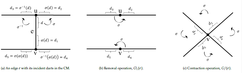
A combinatorial pyramid [15] is a hierarchy of successively reduced combinatorial maps. A combinatorial map (CM) is similar to a graph but explicitly stores the orientation of edges around each vertex. The 2D combinatorial map (𝐺) is defined by a triple 𝐺 = (𝐷, 𝛼, 𝜎) where the D is a finite set of darts [14]. A dart is defined as a half edge and it is the fundamental element in the CM’s structure. The 𝛼 is an involution on the set D and it provides a one-to-one mapping between consecutive darts forming the same edge such that 𝛼(𝛼(𝑑)) = 𝑑. The 𝜎 is a permutation on the set D and encodes
consecutive darts around the same vertex while turning counterclockwise [16]. Note that the clockwise orientation is denoted by 𝜎−1.
Fig. 1a shows a set adjacent darts with their 𝜎 and 𝛼 encoding. Note that the edge 𝑒 between two vertices 𝑢 and 𝑣 is denoted by 𝑒 = (𝑑, 𝛼(𝑑)). The 𝑢, 𝑣 ∈ 𝑉 and the 𝑒 ∈ 𝐸 where the 𝑉 and 𝐸 are the set of vertices and edges of the graph 𝐺 = (𝑉, 𝐸), respectively.
The removal and the contraction operations in the combinatorial pyramid is defined as follows:
Definition 2 (Removal operation). The removal operation removes one edge, 𝐺\{𝑒}, while it modifies the adjacent darts such that:
$$\sigma(\sigma^{-1}(d)) = \sigma(d), \quad \sigma(\sigma^{-1}(\alpha(d))) = \sigma(\alpha(d)) \tag{1}$$
Definition 3 (Contraction operation). The contraction operation removes one edge, 𝐺/{𝑒}, and collapses its two endpoints and modifies the adjacent darts such that:
$$\sigma(\sigma^{-1}(d)) = \sigma(\alpha(d)), \quad \sigma(\sigma^{-1}(\alpha(d))) = \sigma(d) \tag{2}$$
Fig. 1b and Fig. 1c illustrate the removal and contraction operations in the combinatorial map. Note that the contraction operation does not disconnect the graph, and thus preserves connectivity [8].
2. Edge Classification in a Binary Image Graph
Let neighborhood graph 𝐺 = (𝑉, 𝐸) be the undirected connected plane graph consisting of a finite set of vertices 𝑉 and a finite set of edges 𝐸. In the neighborhood graph of the binary input image, each connected component (CC) consists of a set of vertices with the same gray value, 0 or 1. In the paper, black pixels (vertices) are shown by 0 while white pixels (vertices) are shown by 1. In this regard, we partition the edges of the neighborhood graph into two categories: edges connecting two vertices of the same CC, intra-CC and edges connecting vertices of different CCs, inter-CCs as follows:
Definition 4. Intra-CC edge: an edge 𝑒 = (𝑢, 𝑣)∈ 𝐸 within a CC is intra-CC iff 𝑔(𝑢) = 𝑔(𝑣).
Definition 5. Inter-CC edge: an edge 𝑒 = (𝑢, 𝑣)∈ 𝐸 between two CCs is inter-CC iff 𝑔(𝑢) ≠ 𝑔(𝑣).
The contrast of an intra-CC edge is equal to zero, 𝑐(𝑖𝑛𝑡𝑟𝑎-𝐶𝐶) = 0. Therefore, we denote the intra-CC edge by 𝑒0 ∈ 𝐸0. The contrast of an inter-CCs edge is one, 𝑐(𝑖𝑛𝑡𝑒𝑟-𝐶𝐶𝑠) = 1. Therefore, the inter-CCs edge is denoted by 𝑒1 ∈ 𝐸1. All edges in the neighborhood graph are partitioned into 𝐸0 and 𝐸1 edges:
$$E = E_0 \dot{\cup} E_1 \tag{3}$$
3. Selecting the CKs using a Total Order
Selecting the CKs plays the main role in constructing the irregular pyramid. The height of the built pyramid and the complexity of the construction depends on how the CKs are selected. In order to achieve an efficient and a unique selection of the CKs a total order is defined over the vertices [17]. Consider 𝐺 as the neighborhood graph of an binary input image with 𝑀 by 𝑁 vertices. Let (1, 1) be the coordinate of the vertex at the upper-left corner and (𝑀, 𝑁) at the lower-right corner. Let 𝑟 and 𝑐 denote the row and the column in the grid structure of 𝐺, respectively. The vertices of 𝐺 receive a unique index as follows:
$$Idx : [1, M] \times [1, N] \mapsto [1, M \cdot N] \subset \mathbb{N} \tag{4}$$
$$Idx(r, c) = (c – 1) \cdot M + r \tag{5}$$
We use the properties of the total order [18] in selecting the CKs. First, every two elements of a total ordered set (indices of vertices) are comparable. Second, each subset of the total ordered set (a set of vertices) has exactly one minimum and one maximum.
In the binary neighborhood graph 𝐺 a CC consists of only intra-CC (𝐸0) edges. In constructing the irregular pyramid this CC is shown by only one single vertex at the top of the pyramid. Therefore, all the CKs are selected only from the intra-CC edges. From the vertex point of view, a vertex that is not incident to an intra-CC edge is an isolated vertex. This vertex is surrounded by only inter-CC edges.
Let 𝑣 be a non-isolated vertex, i.e, it is the endpoint of at least one intra-CC edge. The upper neighborhood 𝒩 is defined as follows :
$$\mathcal{N}(v) = \{ w \in V \mid (v, w) \in E_0,\ Idx(w) > Idx(v) \} \tag{6}$$
1All total orders are permutations of each other.
The cardinality of the set |𝒩(𝑣)| indicates the number of intra-CC edges incident to 𝑣 having greater vertex than 𝑣. Therefore, the cardinality of the non-isloated vertex is |𝒩(𝑣) ≥ 1|.
In order to determine the CKs in the graph 𝐺 = (𝑉, 𝐸), the selecting contraction kernel SCK(.) function is defined as follows:
$$SCK : [1, M \cdot N] \mapsto [1, M \cdot N] \tag{7}$$
$$SCK(Idx(v)) = \max\{Idx(w) \mid w \in \mathcal{N}(v)\} \text{ if } |\mathcal{N}(v)| \geq 1 \tag{8}$$
$$SCK(Idx(v)) = Idx(v) \text{ if } |\mathcal{N}(v)| = 0 \tag{9}$$
The output of the SCK function partitions the vertices into two categories: surviving vertices and non-surviving vertices as follows:
Definition 6. [Surviving vertex] A vertex 𝑣 ∈ 𝑉 in a binary neighborhood graph 𝐺 = (𝑉, 𝐸), is a surviving vertex iff 𝑆𝐶𝐾(𝐼𝑑𝑥(𝑣)) = 𝐼𝑑𝑥(𝑣).
Proposition 1. An isolated vertex survives always. Proof. Assume 𝑣 is an isolated vertex. Since there is no intra-CC edge incident to the isolated vertex, it leads to|𝒩(𝑣)| = 0. Based on the (9), 𝑆𝐶𝐾(𝐼𝑑𝑥(𝑣)) = 𝐼𝑑𝑥(𝑣) and therefore employing the Def. 6 𝑣 is the surviving vertex.
Definition 7 (Non-surviving vertex). A vertex 𝑣 ∈ 𝑉 in a binary neighborhood graph 𝐺 = (𝑉, 𝐸), is a non-surviving vertex iff 𝑆𝐶𝐾(𝐼𝑑𝑥(𝑣)) ≠ 𝐼𝑑𝑥(𝑣).
Proposition 2. For a non-surviving vertex 𝑣 at the base level,|𝒩(𝑣)| ∈ {1, 2}.
Proof. Based on (5) a non-surviving vertex may be incident to maximum two vertices with greater indices (right or down vertices) at the base level. In addition, the non-surviving vertex must be incident to at least one vertex, namely its right or its down vertex. The former states |𝒩(𝑣)| = 2 while the latter states |𝒩(𝑣)| = 1.
In a CK there is one surviving vertex (the root of the CK) while the remaining vertices are non-surviving vertices. Each non-surviving vertex connects to the surviving root by a unique monotonically 𝐼𝑑𝑥-increasing path of oriented edges. In a graph with 𝑛 vertices there are 𝑛! different total order1. Each selected total order has its own properties. Selecting an efficient total order effects on selecting the CKs where the number of CKs determines the height of the pyramid. Pyramids with logarithmic height reduce the parallel computational complexity of fundamental operations such as connected component labeling [19, 17] and distance transform [20]. Therefore, a proper selection of the total order must result in constructing the pyramid with logarithmic height. In Sec. 4.1 it is proved that the proposed total order leads to this logarithmic height.
In contrast to the common methods of constructing the pyramid [2, 8], using the proposed total order has the advantage that the vertices are partitioned in every level of the pyramid. In other words, the vertices are either the non-surviving or the surviving vertices. Next sections show how this partitioning reduces the number of steps in selecting the CKs into only two steps.
3.1. First Step of Selecting the CKs
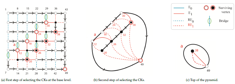
Selecting the CKs at the base level of the pyramid is the first step of the selection. To this aim, the SCK function is performed over each vertex of the neighborhood graph of the base level. As the result, each CK has one surviving vertex and all the other vertices of the CK do not survive. In Fig. 2-a the surviving vertices at the base level are denoted by a red circle around each vertex while all the other vertices do not survive.
At the base level of the pyramid, all faces in the grid structure are bounded by four edges containing two horizontal and two vertical edges.
Proposition 3. A horizontal intra-CC edge in a face of degree 4 at the base level of the pyramid always belongs to a CK.
Proof. Assume a horizontal intra-CC edge 𝑒 = (𝑢, 𝑣) at the base level does not belong to a CK. Let 𝑢 and 𝑣 locate at the left and the right side of the edge 𝑒, respectively. Since 𝑢 is the endpoint of 𝑒, thus 𝑢 is not an isolated vertex (|𝒩(𝑢)| > 1) and based on (5), 𝐼𝑑𝑥(𝑢) < 𝐼𝑑𝑥(𝑣). Due to Pro. 2 if |𝒩(𝑢)| = 1 then 𝑣 is the only vertex of 𝒩(𝑢) that is incident to 𝑢 and thus 𝑣 is selected as the survivor. In case |𝒩(𝑢)| = 2, there are two right and down vertices in the 𝒩(𝑢) where based on (5) the right vertex is selected as surviving vertex.
3.2. Redundant Edges
Graphs as a versatile representative tool may have many unnecessary (redundant) edges [17]. Through the construction of the pyramid, contracting edges results in a smaller induced graph at the upper level. The resulting graph may consist of empty self-loops or double-edges. At this point, the edge removal simplifies the graph and removes these redundant edges.
Definition 8 (Redundant Edges). In a hierarchical structure, those edges that are not needed to fully reconstruct the hierarchy are considered as redundant edges.
Generally, the definition of the redundant edges de- pends on the applications and to what extend the reconstruction needs to be performed. For example, in [6, 17, 19], the authors defined the concept of the redundant edges in a binary graph pyramid in order to do the connected component labeling task where the fully reconstruction is performed. They showed that the redundant edges can be detected (predicted) before performing the contraction of edges. In this paper, we use the same concept for defining the redundant intra-CC and redundant inter-CC edges.
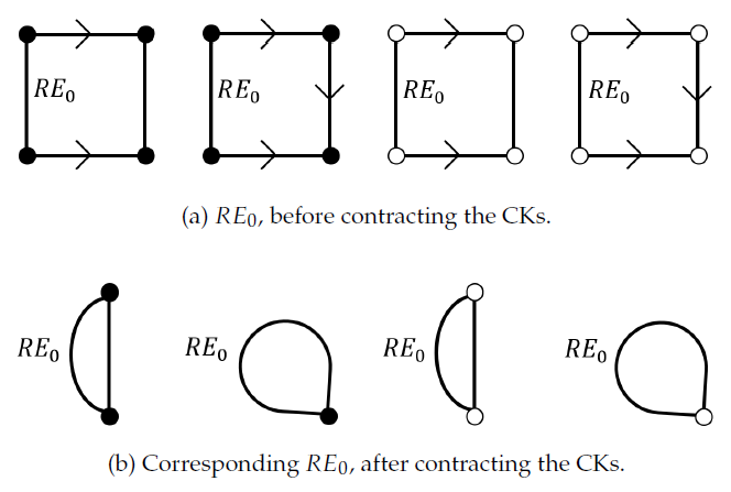
Definition 9 (Redundant Intra-CC edge (𝑅𝐸0)). In an empty face consisting of only intra-CC edges, the non-oriented edge incident to the vertex with lowest Idx is a redundant intra-CC edge.
The definition above states that a redundant intra-CC edge (𝑅𝐸0) exists only in a face bounded by intra-CC edges. Fig. 3 illustrates the configuration of the redundant intra-CC edges.
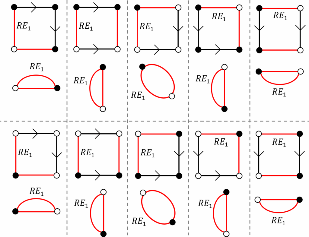
Definition 10 (Redundant Inter-CCs Edge (𝑅𝐸1)). In an empty face, an inter-CCs edge incident to the vertex with lowest Idx is redundant iff:
- The empty face consists of only two inter-CCs
- The empty face is bounded by inter-CCs edges and oriented intra-CC edges.
Fig. 4 illustrates all different configurations of the 𝑅𝐸1 edges before and after contracting the CKs.
3.3. Second Step of Selecting the CKs
At the base level of the pyramid there are three types of the intra-CC edges:
- The oriented edges that belong to the
- The non-oriented redundant edges, 𝑅𝐸0, were defined in Def. 9.
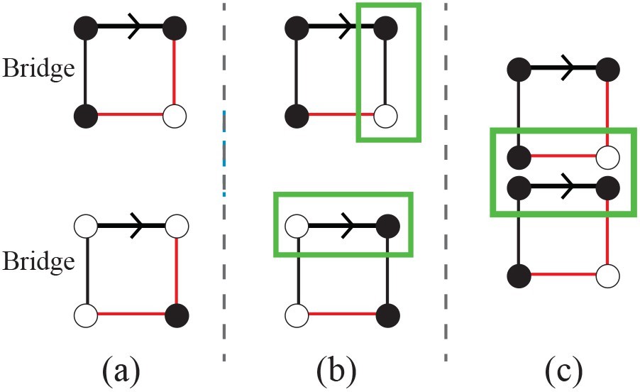
- The remaining non-oriented intra-CC edges are de- fined as the bridges.
Definition 11 (Bridge). A bridge is a non-oriented intra-CC edge that bridges the gap between two contraction kernels of a connected component.
Note that the bridge is the edge of the equivalent contraction kernel (ECK) that is contracted after the two CKs are contracted.
Proposition 4. A bridge in a face of degree 4 at the base level of the pyramid is the vertical edge.
Proof. In the face of degree 4, there are two horizontal and two vertical edges. Assume the non-oriented bridge is the horizontal edge. However, due to Pro. 3 every horizon- tal intra-CC edge is oriented and therefore it cannot be a non-oriented intra-CC edge.
Proposition 5. A face of degree 4 at the base level of the binary pyramid does not have more than one bridge.
Proof. Assume a face of degree 4 contains two bridges. Since the bridges are vertical intra-CC edges, the oriented intra-CC edge must connect two different CCs which is in contradiction with the definition of the oriented edge (see Fig. 5-b).
Proposition 6. Two bridgesJ at the base level of the binary pyramid are not incident to a same vertex.
Proof. Assume that two bridges are incident to the same vertex. Therefore, the horizontal common edge between their two corresponding faces must be the oriented intra-CC edge and the inter-CCs edge at the same time (see Fig. 5-c) , contradiction.
In order to select the CKs at the second step, the SCK function is performed over the bridges.
Definition 12 (inclusion edge). An inclusion edge is a non- empty self-loop inter-CC edge that preserves the topological inclu- sion relationship between two different CCs.
Note that if the inclusion relationships exists between two different CCs, the inclusion edge is one of the bridges that will be detected after the contractions of oriented edges. In Fig. 2 the inclusion edge is shown by a non-empty self- loop that is denoted by the letter a with the red color.
Proposition 7. All the redundant intra-CC edges are detected at the base level of the binary pyramid.
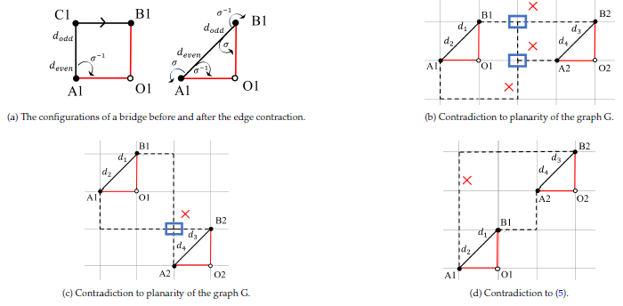
Proof. The redundant intra-CC edges occur in a face bounded by only intra-CC edges. At an upper level, the remaining intra-CC edges are the bridges at the base level. However, since each bridge has the 𝜎-related to a inter-CCs edge (Fig. 6a), therefore, there is no empty face containing only intra-CC edges at upper levels of the pyramid. Note that in the simple graph 𝐺, two bridges cannot be the 𝜎– related of each other because this contradicts to planarity of the graph (Fig. 6b and Fig. 6c) or it contradicts to (5) that is shown in Fig. 6d.
The Proposition .7 states that there is no redundant intra- CC edge at an upper level of the pyramid. In fact, this is because of the important property of the defined total order over the indices of vertices where at the base level each non-surviving vertex only can be contracted into its right or down neighborhood vertex.
4. Fast Labeled Spanning Tree (FLST)
A CC in a binary graph pyramid is represented by a single surviving vertex at the top level of the pyramid. This vertex is the root of the tree spanning its receptive field at the base level [21]. In [22] it was shown that the combination of two (or more) successive reductions in an equivalent weighting function allows to calculate any level of the pyramid directly from the base. Kropatsch in [21] introduced the Equivalent Contraction Kernels (ECK) in the irregular graph pyramid and it was later used [23] in the minimum spanning tree (MST) segmentation.
In the binary pyramid, every spanning tree of a CC is the MST because the contrast (weight) of the intra-CC edges is zero. To drive the spanning tree of a CC, the previous common methods [14, 16, 11] need to select the CKs in 𝑛 iterations where 𝑛 is the height of the pyramid. In contrast, in the proposed method we only need two steps of selecting the CKs. Moreover, the SCK function is performed locally over each vertex. This means that the CKs are selected with parallel complexity of 𝒪(1). Note that, it is assumed there are sufficient processing elements available in order to do the parallel computations.
4.1. Independent Edges
To contract the CKs in a parallel manner, finding a set of independent edges plays the key role. Dependency of the edges differs based on what processing is going to be per- formed between a set of edges. In [19] two edges not sharing an endpoint are considered as independent edges. Using this definition all the CKs at the first selection can be contracted with parallel complexity bounded as follows:
$$\mathcal{O}(\log_{2}(\delta(\text{CK}))) \leq \text{CKs contraction} \leq \mathcal{O}(\log_{3}(\delta(\text{CK})))\tag{10}$$
To determine the parallel complexity of contracting the CKs at the second step of selection, the dependencies between darts [6] is considered. Since in this step, each edge of the CK is a bridge at the base level, hence, there is an inter-CCs edge with a 𝜎-relation incident to this edge. Therefore, all the CKs at the second selections are independent of each other and they will be contracted in parallel complexity 𝒪(1).
5. Applications
To highlight the usefulness of the proposed method, two main applications are presented. In both application the parallel complexity is 𝒪(𝑙𝑜𝑔(𝑁 )) in a 𝑁 × 𝑁 -size input binary image.
5.1. Connected Component Labeling
Connected Component Labeling (CCL) is a fundamental task in analyzing binary images [24] where background and foreground are denoted by zero and one, respectively. A connected region is a group of pixels where all pairs of pixels are connected together. The role of the CCL is to assign a unique label to each CC. Common methods of CCL [24, 25, 26] are linear; i.e., they search the binary image row by row in the raster-scan fashion. In contrast, using a hierarchical structure, within the bottom-up construction each pixel reaches its single surviving pixel (super-pixel) at top of the pyramid in a logarithmic number of steps. At this top-level of the pyramid, each of the super-pixels receives its unique label 𝐼𝑑𝑥. Afterwards, through the top-down propagation the vertices of the lower levels inherit the labels from the higher levels until all the pixels at the receptive field (base level of the pyramid) received their labels.
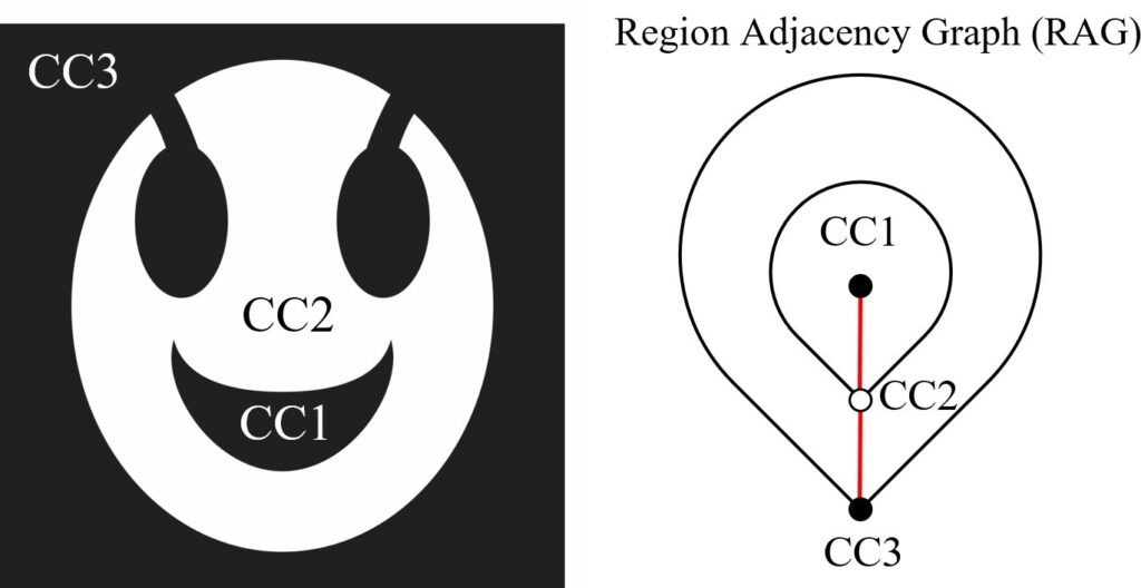
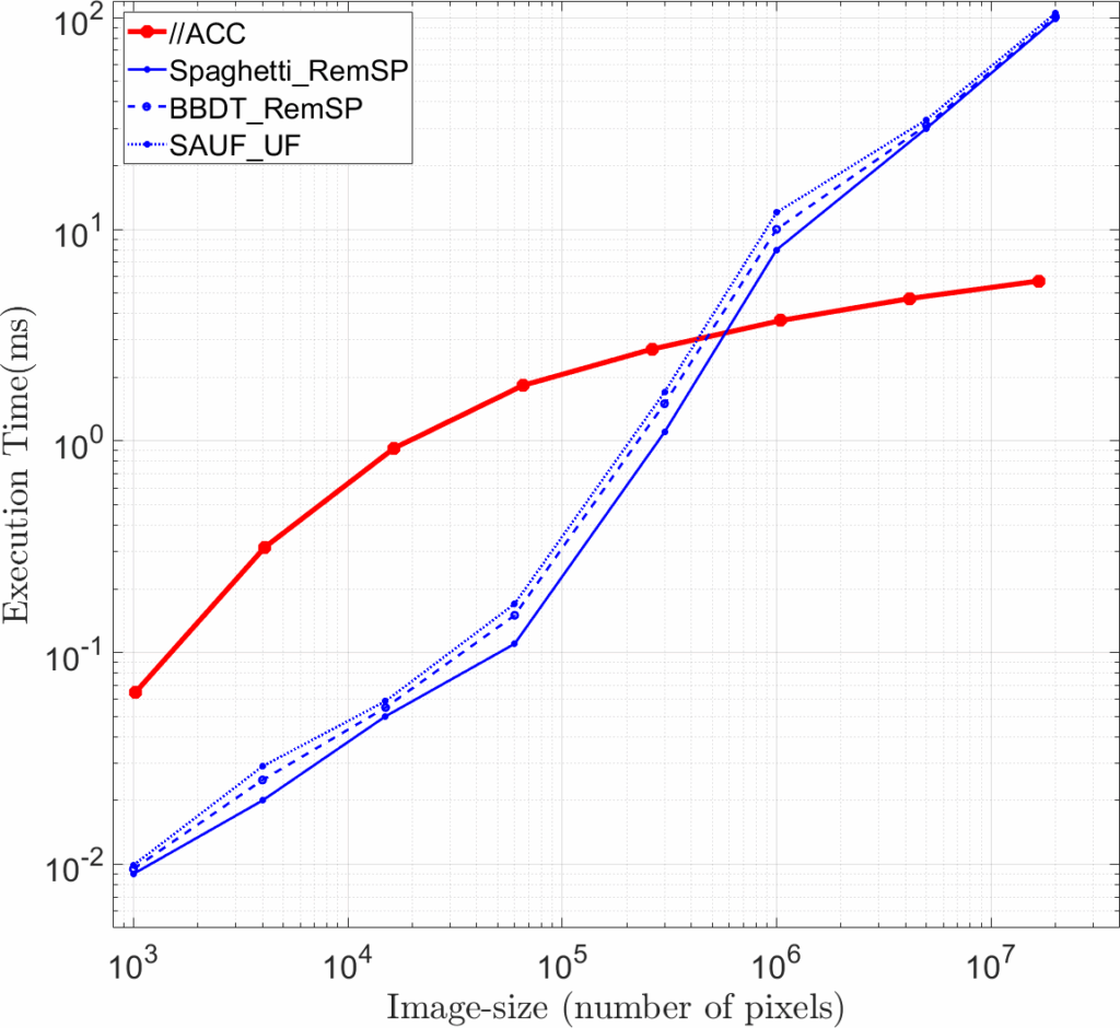
The hierarchical method is called Parallel Pyramidal Connected Component (//ACC2) where the details can be found in [19]. The //ACC not only does the CCL task but also preserves the topological relations between the CCs. Fig. 7 shows how the //ACC encodes inclusion relation- ships between three CCs. Table 1 [19] shows the execution time of the //ACC method over three different categories of binary images; Random, MRI and Finger-print images. In addition, the execution time of the algorithm over different image-size is compared to the state-of-the-art methods; Spaghetti_RemSP, BBDT_RemSP, SAUF_UF, in [27]. The results in Fig. 8 encourage the //ACC method should be used in large images including more than one million pixels.
Table 1: Results for the different categories from (YACCLAB[28]).
Database Type | Random | MRI | Finger-print |
size of Images | 128×128 | 256×256 | 300×300 |
Num. of Images | 89 | 1170 | 962 |
mean time (ms) | 0.098 | 1.643 | 2.317 |
worst time (ms) | 0.127 | 2.973 | 3.518 |
5.2. Distance Transform
The distance transform (DT) is another important fundamental operation that is applied to the binary image [1]. It is employed in a broad range of applications containing template matching [29, 30], image registration [31], map matching robot self-Localization [32], skeletonization [33], Line Detection in Manuscripts [34], Weather Analysis and Forecasting [35], etc. After applying the DT to a binary image, the result of the transform is a new gray-scale image whose foreground 1 pixels have intensities representing the minimum distance from the background 0 pixels.
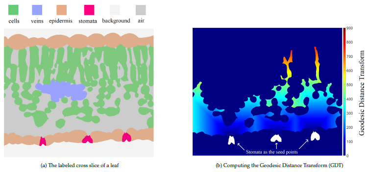
In order to compute the DT, the common methods [1, 36], propagate the distances in linear sequential time. By con- trast, using the hierarchical structure the distances can be propagated by a set of power-of-two numbers [20] where the parallel complexity is reduced into the logarithmic-time. The computation of DT with lower complexity makes the pyramid as a useful tool in analysing large binary images. In particular, currently we are working on the Water’s gateway to heaven project3 dealing with high-resolution X-ray micro- tomography (𝜇𝐶𝑇) and fluorescence microscopy. The size of the images is more than 2000 in each of 3 dimensions where we use the saddle points of the DT to separate cells, which are visually difficult to be separated.
In the mentioned project above the input image is a labeled 2D cross slice of a leaf scan where it has six different labels illustrating different regions inside the leaf (Fig. 9a). The task of stomata is to control the amount of CO2 that is entering the leaf. In order to do the photosynthesis, the CO2 propagates through the airspace inside the leaf to reach the cells where it combines with water and sunlight. To model the procedure of the gas exchange in the leaf [37], we compute the geodesic distance transform (GDT) from the stomata through the airspace (Fig. 9b) to find out how long it takes to reach the necessary CO2 concentration [20]. The use of pyramids would enormously speed up the computations of the DT in the large images of the project.
6. Conclusion
The paper presents a fast parallel method to select the equivalent contraction kernels in the irregular pyramid of a binary input image. It was shown that the first step of selecting the contraction kernels (CKs) at the base level is done with parallel complexity 𝒪(1). These CKs are contracted with parallel 𝒪(𝑙𝑜𝑔(𝛿)) complexity where the 𝛿 is the diameter of the maximum connected component (CC)
2It is pronounced pac where the // and A stand for parallel and pyramidal.
3https://waters-gateway.boku.ac.at/
in the neighborhood graph of the image. By detecting the redundant edges (RE) the selection of CKs is performed in one parallel step. By defining the independent set of edges, we proved that all the selected CKs at the second step of selection are contracted in parallel complexity 𝒪(1). The Fast labeled spanning tree (FLST) of the CCs is produced with parallel complexity 𝒪(𝑙𝑜𝑔(𝛿)). Using the total order there is no random processing in construction of the pyramid and the resulting FLST is unique.
In addition, it was shown by employing the proposed FLST, that the fundamental operations in analyzing the binary image can be performed in lower parallel complexity. In particular, two main operations, connected component labeling (CCL) and distance transform (DT), were presented in detail. Finally, we presented how the proposed method can be useful in processing of the large images in practical real applications. For future works we plan to compute 3D distance transform in order to study the diffusion in the air space within a leaf.
Conflict of Interest The authors declare no conflict of interest.
Acknowledgment We acknowledge the Paul Scherrer In- stitut, Villigen, Switzerland for provision of beamtime at the TOMCAT beamline of the Swiss Light Source and would like to thank Dr. Goran Lovric for assistance. This work was supported by the Vienna Science and Technology Fund (WWTF), project LS19-013, and by the Austrian Science Fund (FWF), projects M2245 and P30275.
- A. Rosenfeld, J. L. Pfaltz, “Sequential operations in digital picture processing”, Association for Computing Machinery, vol. 13, no. 4, p. 471–494, 1966.
- P. Meer, “Stochastic image pyramids”, Computer Vision, Graphics, and Image Processing, vol. 45, no. 3, pp. 269–294, 1989.
- Z. Pizlo, Problem Solving, Cognitive Mechanisms and Formal Models, Cambridge University Press, 2022.
- M. C. Potter, B. Wyble, C. E. Hagmann, E. S. McCourt, “De- tecting meaning in rsvp at 13 ms per picture”, Attention, Per- ception, & Psychophysics, vol. 76, no. 2, pp. 270–279, 2014, doi: 10.3758/s13414-013-0605-z.
- J. A. Feldman, D. H. Ballard, “Connectionist models and their proper- ties”, Cognitive science, vol. 6, no. 3, pp. 205–254, 1982.
- M. Banaeyan, W. G. Kropatsch, “Pyramidal connected component labeling by irregular graph pyramid”, “2021 5th International Conference on Pattern Recognition and Image Analysis (IPRIA)”, pp. 1–5, 2021, doi:10.1109/IPRIA53572.2021.9483533.
- J.-M. Jolion, A. Rosenfeld, A pyramid framework for early vision: mul- tiresolutional computer vision, vol. 251, Springer Science & Business Media, 2012.
- W. G. Kropatsch, “Building irregular pyramids by dual graph con- traction”, IEE-Proc. Vision, Image and Signal Processing, vol. Vol. 142, no. No. 6, pp. pp. 366–374, 1995, doi:10.1049/ip-vis:19952115.
- W. G. Kropatsch, H. Macho, “Finding the structure of connected components using dual irregular pyramids”, “Cinquième Colloque DGCI”, pp. 147–158, LLAIC1, Université d’Auvergne, ISBN 2-87663- 040-0, 1995.
- Y. Haxhimusa, W. G. Kropatsch, “Segmentation graph hierarchies”, “Structural, Syntactic, and Statistical Pattern Recognition, Joint IAPR International Workshops on SSPR 2004 and SPR 2004”, vol. LNCS 3138, pp. 343–351, Springer, Berlin Heidelberg, New York, 2004.
- M. Cerman, I. Janusch, R. Gonzalez-Diaz, W. G. Kropatsch, “Topology-
ng LBP pyramids”, Machine Vision and ons, pp. 1–14, 2016, doi:10.1007/s00138-016-0795-1. - R. Klette, Concise computer vision, vol. 233, Springer, 2014.
- R. Trudeau, Introduction to Graph Theory, Dover Books on Mathematics, Dover Pub., 1993.
- L. Brun, W. G. Kropatsch, “Hierarchical graph encodings”, O. Lézoray,L. Grady, eds., “Image Processing and Analysis with Graphs: Theory and Practice”, pp. 305–349, CRC Press, 2012.
- L. Brun, W. Kropatsch, “Introduction to combinatorial pyramids”, “Digital and Image Geometry”, pp. 108–128, Springer, 2001.
- F. Torres, W. G. Kropatsch, “Canonical encoding of the combinato- rial pyramid”, “Proceedings of the 19th Computer Vision Winter Workshop”, pp. 118–125, 2014.
- M. Banaeyan, D. Batavia, W. G. Kropatsch, “Removing redundancies in binary images”, “International Conference on Intelligent Systems and Patterns Recognition (ISPR), Hammamet, Tunisia, March 24-25, 2022”, pp. 221–233, Springer, 2022, doi:10.1007/978-3-031-08277-1_19.
- B. A. Davey, H. A. Priestley, Introduction to lattices and order, Cambridge university press, 2002.
- M. Banaeyan, W. G. Kropatsch, “Parallel 𝑙𝑜 𝑔 𝑛 computation of the adjacency of connected components”, “International Confer- ence on Pattern Recognition and Artificial Intelligence (ICPRAI), Paris, France, June 1-3, 2022”, pp. 102–113, Springer, 2022, doi: 10.1007/978-3-031-09282-4_9.
- M. Banaeyan, C. Carratù, W. G. Kropatsch, J. Hladůvka, “Fast distance transforms in graphs and in gmaps”, “IAPR Joint International Work- shops on Statistical Techniques in Pattern Recognition (SPR 2022) and Structural and Syntactic Pattern Recognition (SSPR 2022), Montreal, Canada, August 26-27, 2022”, p. in print, 2022.
- W. G. Kropatsch, “Equivalent contraction kernels to build dual ir- regular pyramids”, Advances in Computer Science, vol. Advances in Computer Vision, pp. pp. 99–107, 1997.
- P. J. Burt, E. H. Adelson, “The Laplacian pyramid as a compact image code”, “Readings in computer vision”, pp. 671–679, Elsevier, 1987.
- Y. Haxhimusa, A. Ion, W. G. Kropatsch, “Evaluating hierarchical graph-based segmentation”, “18th International Conference on Pat- tern Recognition”, vol. II, pp. 195–198, IEEE Comp.Soc., 2006, doi: 10.1109/ICPR.2006.511.
- L. He, X. Ren, Q. Gao, X. Zhao, B. Yao, Y. Chao, “The connected- component labeling problem: A review of state-of-the-art algorithms”, Pattern Recognition, vol. 70, pp. 25–43, 2017, doi:10.1016/j.patcog.2017. 04.018.
- L. He, Y. Chao, K. Suzuki, “Two efficient label-equivalence-based connected-component labeling algorithms for 3D binary images”, IEEE Transactions on Image Processing, vol. 20, no. 8, pp. 2122–2134, 2011, doi:10.1109/TIP.2011.2114352.
- U. H. Hernandez-Belmonte, V. Ayala-Ramirez, R. E. Sanchez-Yanez, “A comparative review of two-pass connected component labeling algo- rithms”, “Mexican International Conference on Artificial Intelligence”, pp. 452–462, Springer, 2011, doi:10.1007/978-3-642-25330-0_40.
- F. Bolelli, S. Allegretti, L. Baraldi, C. Grana, “Spaghetti labeling: Di- rected acyclic graphs for block-based connected components labeling”, IEEE Transactions on Image Processing, vol. 29, pp. 1999–2012, 2020, doi:10.1109/TIP.2019.2946979.
- C. Grana, F. Bolelli, L. Baraldi, R. Vezzani, “YACCLAB – Yet Another Connected Components Labeling Benchmark”, “2016 23rd Interna- tional Conference on Pattern Recognition (ICPR)”, pp. 3109–3114, Springer, 2016, doi:10.1109/ICPR.2016.7900112.
- S. Prakash, U. Jayaraman, P. Gupta, “Ear localization from side face images using distance transform and template matching”, “2008 First theory, Tools and Applications”, pp.
.1109/IPTA.2008.4743786. - J. Lindblad, N. Sladoje, “Linear time distances between fuzzy sets with applications to pattern matching and classification”, IEEE Transactions on Image Processing, vol. 23, no. 1, pp. 126–136, 2014, doi: 10.1109/TIP.2013.2286904.
- B. Hill, R. A. Baldock, “Constrained distance transforms for spatial atlas registration”, BMC bioinformatics, vol. 16, no. 1, pp. 1–10, 2015, doi:10.1186/s12859-015-0504-5.
- H. Sobreira, C. M. Costa, I. Sousa, L. Rocha, J. Lima, P. Farias, P. Costa, P. Moreira, “Map-matching algorithms for robot self-localization: a comparison between perfect match, iterative closest point and normal distributions transform”, Journal of Intelligent & Robotic Systems, vol. 93, no. 3, pp. 533–546, 2019, doi:10.1007/s10846-017-0765-5.
- C. Niblack, P. B. Gibbons, D. W. Capson, “Generating skeletons and centerlines from the distance transform”, CVGIP: Graphical Models and Image Processing, vol. 54, no. 5, pp. 420–437, 1992.
- M. Kassis, J. El-Sana, “Learning free line detection in manuscripts using distance transform graph”, “2019 International Conference on Document Analysis and Recognition (ICDAR)”, pp. 222–227, 2019, doi:10.1109/ICDAR.2019.00044.
- D. Brunet, D. Sills, “A generalized distance transform: Theory and applications to weather analysis and forecasting”, IEEE Transactions on Geoscience and Remote Sensing, vol. 55, no. 3, pp. 1752–1764, 2017, doi:10.1109/TGRS.2016.2632042.
- R. Fabbri, L. D. F. Costa, J. C. Torelli, O. M. Bruno, “2D eu- clidean distance transform algorithms: A comparative survey”, ACM Computing Surveys (CSUR), vol. 40, no. 1, pp. 1–44, 2008, doi: 10.1145/1322432.1322434.
- M. Momayyezi, A. Borsuk, C. Brodersen, M. Gilbert, G. Théroux- Rancourt, D. Kluepfel, A. McElrone, “Desiccation of the leaf meso- phyll and its implications for CO2 diffusion and light processing”, & Environment, vol. 45, no. 5, pp. 1362 – 1381, 2022, doi: 1111/pce.14287.
No related articles were found.