Design Consideration for IGBT-Based PWM Inverter-Fed Induction Motors
(This article belongs to the Section Electrical Engineering (ELE))
Export Citations
Cite
Ogunyemi, J. , Fagbuaro, O. E. and Okeke, H. S. (2022). Design Consideration for IGBT-Based PWM Inverter-Fed Induction Motors. Journal of Engineering Research and Sciences, 1(12), 21–27. https://doi.org/10.55708/js0112004
Joel Ogunyemi, Olawale Ezekiel Fagbuaro and Henry Sunday Okeke. "Design Consideration for IGBT-Based PWM Inverter-Fed Induction Motors." Journal of Engineering Research and Sciences 1, no. 12 (December 2022): 21–27. https://doi.org/10.55708/js0112004
J. Ogunyemi, O.E. Fagbuaro and H.S. Okeke, "Design Consideration for IGBT-Based PWM Inverter-Fed Induction Motors," Journal of Engineering Research and Sciences, vol. 1, no. 12, pp. 21–27, Dec. 2022, doi: 10.55708/js0112004.
Pulse width modulated (PWM) inverter has applications in many areas as it offers control of voltage, frequency, and harmonic in one power stage. In the practical design of three-phase inverter circuits, a proper understanding of the operations and peculiarities of the specific model to be built is necessary. Most often, perhaps due to different models and configurations; these details are often omitted or assumed to be obvious. An IGBT-based PWM inverter for a 0.5hp induction motor was designed and implemented. Though the implementation posed a challenge to realize, the experience obtained during the process informed the design consideration presented in this paper. The power supply requirements, gate drive requirements, driver protection and dv/dt protections are necessary considerations for successful implementation. This paper presents detailed specific requirements when designing a PWM inverter with IGBT as a driver for induction motor application. The focus is on the theoretical analysis and important design considerations during the practical implementation of an inverter. Different stages involved are analyzed and discussed from the input stage to the output load section. The model used involved single-phase ac input which is rectified to dc. At the output of the rectifier is a large filter capacitor to maintain a constant dc link voltage. The insulated gate bipolar transistor was used as a switching device to drive the 0.5hp induction motor. The analysis simplified inverter design, especially for beginners.
1. Introduction
The growing need for variable voltage and frequency has increased the popularity of inverter circuits in the industry. Some of the control strategies which made this possible are voltage control or six-step, pulse width modulation current control techniques [1]. Minimization of harmonics and ripple in torques can be achieved by the PWM control technique and properly selected filter[2,3,4]. The PWM technique can be categorized into various types according to different patterns of reference signal [5]. Thus, the inverters formed are named after each technique. For controlling PWM, it involves turning ON and OFF the switch continuously during a half-cycle and the output voltage is controlled by varying the width of the pulses [6]. The driving force behind the usage of AC drives system is the cost, maintenance, size reliability and efficiency advantages of the ac induction motor.
Though the use of conventional methods for generating PWM causes variable frequencies at the output of an inverter [7]-[9]; they are still popular because of easy implementation and cost-effectiveness. PWM can be an open loop or a closed loop configuration depending on how the generated voltage reference is used. It is directly given as a reference in the open loop while it is fed to the controller in the closed loop [10]. PWM inverter has its area of application in industrial motor drives and uninterrupted power supply (UPS) systems as it has excellent modes of speed control of the induction motor [11]. The high efficiency and superiority of induction motors over DC motors are factors responsible for the high rising of their usage in industries [12], [13]. With renewable energy on the increase in recent times, an inverter which serves as a link to the grid will continue to find application in this area as well [14]. The switching element is an insulated gate bipolar transistor (IGBT). Its choice of usage is because of the combination of the advantages of bipolar junction transistor (BJT) with that of metal oxide semiconductor field effect transistor (MOSFET). Each of the IGBTs is switched between the dc poles to give the ac output [15]. Previous works revealed the simulation method [7] and practical implementation of the PWM stages [8]. This paper now focuses on the other details involved during the practical implementation of an inverter circuit. The full results and performance test analysis of the inverter are not reported in this paper.
2. Material And Methods
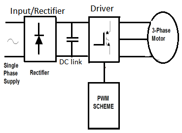
To design and implement successfully a three-phase inverter circuit, a proper understanding of the operations and peculiarities of the specific model to be built is necessary. This paper presents detailed specific requirements when designing a PWM inverter with IGBT as a driver for induction motor application. The stages involved are segmented into five sections. They are the input/rectifier, capacitance dc link, IGBT driver, PWM stage and AC induction motor. The theoretical analysis and design considerations involved in practical implementations were highlighted. Figure 1 shows the block diagram for the whole system. Each of the sub-sections is discussed next.
2.1. Input /Rectifier Design Stage
DC sources for inverters can be from renewable energy sources such as solar, wind etc depending on other factors. It can be from the grid also for ac-dc-ac operation as illustrated in this work. The input stage for the inverter considered is AC power supply from the grid. AC supply has been chosen as the source of supply because of its wide acceptability and most used form of power supply, especially in the industry. The input dc to the inverter is a rectified single phase ac supply. The rectification process is usually done to reduce the harmonic content in the supply current and thus produces a high input power factor [4]. Single-phase supply input is used in this work because the load is relatively small (0.5hp/0.37kw induction motor). Though the 3-phase is commonly used for industrial applications, the same approach for the single-phase used in this paper can also be adopted with necessary modifications. A resistor is placed in the input to prevent a large inrush current during startup [16].
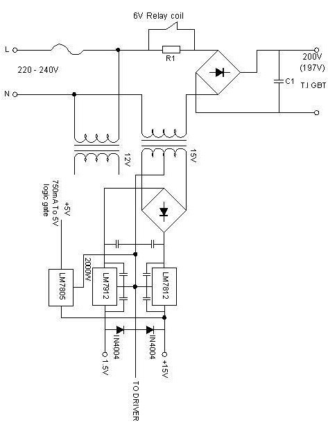
For the operation of an inverter, different stages may require different power supplies due to various voltage demands in the circuit. They are high-voltage and low-voltage sections. In this model, the high voltage source is for the inverter to drive the load. This is achieved by directly converting the 220 a.c source to its equivalent d.c source using a full bridge rectifier. A capacitor is then used to filter the ripple. Note that no transformer is involved in this case.
The low voltage d.c source stage is further made up of two sections:
- +15V supply: this section supplies both positive and negative voltage to the PWM control/driver circuit.
- +5V supply: this supplies to the logic circuit.
A 15V step-down transformer is used to supply both circuits with voltage regulators LM7815, LM7915 and LM 7805 to obtain +15V, -15V and +5V respectively from the rectifier output as shown in Figure 2.
The second stepdown transformer of 12V rating in Figure 2 is used to supply the phase shift circuit (PSC) as discussed in [7]. Details are therefore not presented here for brevity.
3. Design analysis
The design of a rectifier involves the determination of the ratings of diodes which are normally specified in terms of average currents, rms current, peak current and Peak Inverse Voltage (PIV).
For the D.C link (being a highly inductive load), the power is given by equation 1 as:
$$P = VI \cos{\theta}\tag{1}$$
The phase current is then given by equation 2 as:
$$I = \frac{P}{V \cos \theta}\tag{2}$$
Substituting for the values of P, V and power factor cos as 370W, 220V and 0.75 respectively.
$$= \frac{370}{220 \times 0.75} = 2.24\,\text{A}$$
The average load current is chosen as 2.5A assuming the ripple is negligible.
For the peak inverse voltage PIV:
$$\text{PIV} = \sqrt{2} \times 220 = 311\,\text{V}.$$
Based on this design, a 400V diode is chosen.
The line-to-neutral voltage of 220V/50Hz is the average current of the diode given by:
Id = 2.5/0.5 A =5A
3.1. Capacitance Link (DC Link) Stage
For voltage–source inverter, a large filter capacitor is placed across the inverter input terminals to maintain a constant stiff dc link voltage and to reduce low-order harmonics [17]. Because of the large value of C, the time constant RC is also large compared with the periodic time (0.02s for 50Hz) of the applied voltage [16]. There is an exponential decay of the voltage across the load as against a sinusoidal fall given by equation 3.
$$V = V_{\text{max}} \mathrm{e}^{-\frac{t}{RC}}\tag{3}$$
To be effective, the reactance, xc of the capacitor should be relatively minimal compared with the resistance R. To keep ripple less than 1Vp-p, the required capacitor is given by equation 4 as:
$$C = \frac{I * T}{2 * V_{p-p}} = \frac{I * T}{2 * f * V_{p-p}}\tag{4}$$
where I is current, T is period and f is the frequency.
For a current of 2.5A obtained above and 50Hz supply frequency, the value of the capacitor required is:
C = 2.5/(2x50x0.1)
C = 2,500μf
A 2,500μf capacitor is chosen.
3.2. Insulated Gate Bipolar Transistor (IGBT) Driver Stage
When designing a gate drive circuit for IGBT, it requires that the gate charge is used rather than the components value based on the gate capacitance listed in the datasheet. This is because the RC values based on them normally lead to inadequate values because of the Miller effect. A gate charge is defined as the charge that must be supplied to the gate to swing the gate by a given charge known [18]. The required gate drive current is derived by dividing the gate charge by the required switching time. The circuit impedance can equally be determined. The gate charge data also allows the determination of average gate drive power. The lower the charge, the lower the gate drive current needed to achieve a given switching time [19]. Equation 5 gives the average gate drive power as:
$$P_G = Q_G \cdot V_G \cdot F\tag{5}$$
where PG is gate power, QG is the total charge and f is frequency.
3.3. Opto-coupler
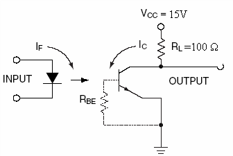
To isolate the control circuit from the power circuit, an opto-coupler is necessary. An optical isolator is to provide protection from high-voltage transient, surge voltages and low-level electrical noise that could damage the device or from erroneous output [18]. They allow the interfacing of a circuit with different voltage levels and different ground. An opto-coupler consists of a light source such as LED and a photo detector [19]. Figure 3 shows the circuit diagram of the opto-coupler used.
3.4. Driver Output Stage
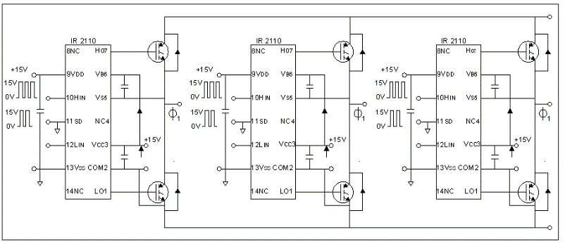
The output section of the inverter is driven by the driver circuit according to the switching frequency. A specially designed driver IC by International Rectifier (IR2110) [20] is employed in this model. IR2110 was used to drive the high upper and lower side of the bridge. It provides a simple low-cost high-performance solution to the gate drive requirements [21]. It is a high-voltage, high-speed IGBT driver with independent high and low side referenced output channels. It has a floating channel which can be used to drive the IGBT in the high-side configuration up to 500V maximum. Figure 6 shows the final stage of the IGBT PWM inverter circuit with the IR2110 Driver
4. Gate Drive Circuit Design
The gate charge Qg for the IGBT used (IRG4PH50U) is 160 nC from the datasheet. The total capacitance gate (Cg) is obtained from
$$Q_T = C_g V_g\tag{6}$$
With the gate voltage of 15V,
Cg = QT/Vg
= 160 x 10-9/15
=10.67nF
The power required to charge the gate is calculated as:
$$P_g = \frac{1}{2} C_g V_g^2 f\tag{7}$$
where f is the switching frequency.
With a switching frequency of 1500Hz, from equation 7 we have:
`Pg = 0.5 x 10.67 x 10-9 x 152 x 1500
= 1.8mW.
The power dissipated (PD) in the gate drive circuitry can be obtained from equation 8 as:
$$P_D = C \cdot V^2 \cdot f\tag{8}$$
where C is the total capacitance gate obtained above; V is the gate voltage and f is the switching frequency. Substituting for the values, we have:
PD = 10.67 x10-9 x 152 x 1500= 3.6mW.
5. Driver Protection
To provide a path for reverse currents for the totem output transistor, low forward voltage drop Schottky diodes are generally needed to protect the outputs. The diodes must be placed very close to the outputs path to the bypass capacitor of the driver. It should be noted that the diodes protect the driver only and thus they are not clamping the gate-to-source voltage against excessive driving. The driver circuit handles the current spikes and power losses making the operating condition for the PWM controller more favourable. The driver circuits therefore should be placed next to the power IGBT they are driving.
5.1. dv/dt Protection
IGBT must be protected against dv/dt triggered-on during the power-up and in normal operation. During power-up, this is done by a resistor placed between the gate and source terminals of the device. High dv/dt in power supply has been reported to generate high stress on motor windings and thus require additional motor insulation [21]. It also increases the electromagnetic interference (EMI) caused by semiconductor devices.
5.2. PWM Stage
In the three-phase inverter, each half-bridge is fed with the same triangular carrier wave with the reference wave displaced by 1200 for a balance system. For a balanced three-phase operation, it is essential to operate with a carrier ratio that is multiple of three. The ratio of the reference amplitude wave to the carrier wave is termed the Modulation Index.
It determines the notch width in the modulated pole voltage waveform and therefore controls the fundamental output voltage of the inverter [22]. The practical implementation of the PWM techniques has been presented by [8].
The sinusoidal pulse width modulation (SPWM) method popularly used in the industry was adopted with a unique phase shifting technique6,11. The detailed simulation and implementation have been reported [7,8].
5.3. AC Induction Motor (ACIM)
ACIMs are the popular choice of motor control in industries. Some of the advantages of ACIM include simple and rugged design, low maintenance and direct connection to AC power. When power is being supplied to the induction motor at the specified time, it runs at its rated speed. Three-phase induction machine is mostly used in industries as they can deliver more power than the single-phase. Squirrel cage induction motor is the most popular among induction motors. The rotor motor type requires an external resistor and slip rings connection. The squirrel cage motor has a simple and rugged construction. The rotor consists of a cylindrical terminated core with axially placed parallel slots for carrying the windings. Each slot can either be of copper, aluminum or alloy bar and are usually short-circuited at both ends by means of end ring [1]. It forms a case-like cage hence its name.
The stator winding is directly connected to the power source to a create rotating magnetic field rotating at synchronous speed Ns given by equation 9 as:
$$N_s = \frac{120f}{P}\tag{9}$$
where f is the supply frequency in Hertz and P is the number of poles on the stator.
Synchronous speed is the speed at which the stator flux rotates. Rotor flux rotates slower than this synchronous speed by the slip speed. The slip speed is the difference between the synchronous speed and the base speed. That is:
$$\text{Slip speed} = \text{Synch speed}~(N_s) – \text{base speed}~(N_b)\tag{10}$$
The per cent slip is therefore given as:
$$\%\ \text{slip} = \left( \frac{N_s – N_b}{N_s} \right) \times 100\%\tag{11}$$
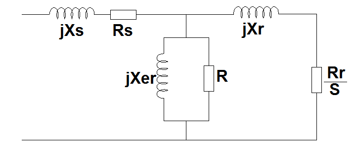
The complete circuit model for induction motor is shown in figure 5.
where: Xs is per phase leakage reactance of stator winding; Rs is the resistance of the stator; Xm is magnetizing reactance; Rm is resistance for excitation; Im is magnetizing current; Rr is rotor resistance and Xr is leakage reactance.
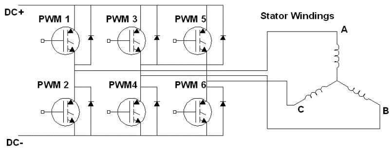
The inverter circuit with a three-phase bridge connected to the motor’s stator winding is shown in Figure 6. The modus-operandi of a three-phase AC induction motor (ACIM) requires a rotating magnetic field which is normally supplied through the stator windings. An inverter-fed induction motor is a popular form of adjustable-speed ac drive, because of its wide availability and low cost [1].
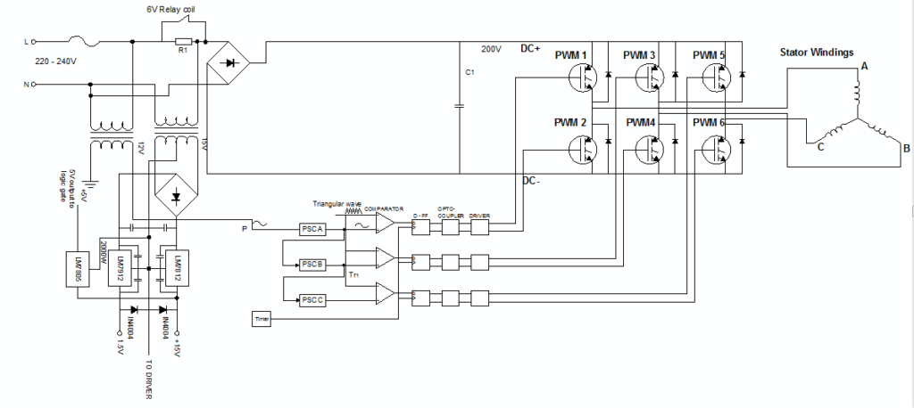
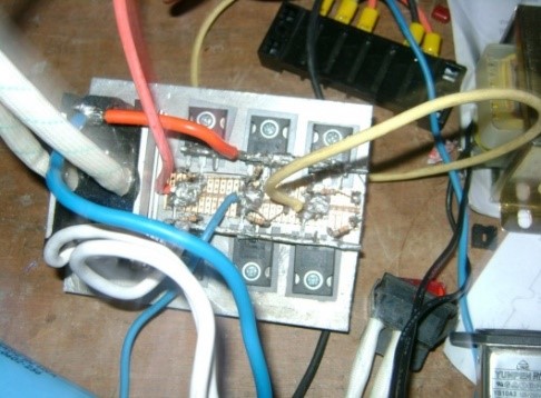
6. Result
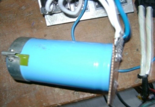
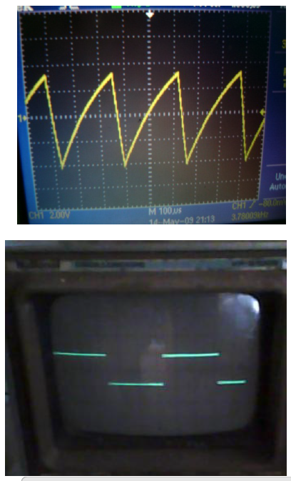
The complete model of the three-phase PWM inverter consists of all the various stages previously highlighted coupled together. Figure 7 shows the complete circuit model under consideration. Figures 8 and 9 show the IGBTs circuitry and DC link capacitor respectively during the practical implementation. The triangular wave and clocking signal used for realizing PWM waveforms obtained during the implementation are shown in Figures 10a and b [8].
7. Discussion
The complete circuit and practical implementation shown in Figures 7-10 confirmed the design analysis to be correct. Though the implementation posed a challenge to realize, the experience obtained during the process informed the design consideration presented in this paper. The gate drive requirements, driver protection and dv/dt protections are necessary for successful implementation [23]. The input power supply stage to three different sections must be properly isolated from each other. Though the simulation results obtained showed the proof of concept for the design was correct [24]. However, the final choice of components differed slightly from the simulation result. The ideal elements are usually employed in a simulation circuit. The most challenging parts of the implementation are the PWM and driver circuits. The problems of grounding, interference etc. associated with analogue circuits are properly handled to get the appropriate signals [25]. The screenshot of the triangular carrier wave from the oscillator circuit and the clocking signal as reported in [8] following the simulation of [7].
8. Conclusion
PWM inverter remains popular among power-electronic circuits in practical applications and will continue to attract research interest. PWM control techniques are one of the ways to improve the harmonic-free environment in high-power converters. This paper has presented the design consideration for a three-phase PWM inverter in induction motor application. Though a single-phase was used in this work, the principle of operation remains like that of three-phase. The design concept earlier simulated showed that the proof of concept used was correct. The easy implementation and control features have been explored to illustrate the design consideration emphasized in this paper. The interconnected circuitry such as power supply stages, DC link, PWM circuit, driver stage and load section. Though the design used analogue techniques, in this smart era of microprocessor-controlled devices; digital implementation will be a better option for improved performance. This paper does not present the full results of the performance test. A details harmonic analysis of the harmonic waveforms is necessary to determine the quality of the waveform.
Conflict of Interest
The authors declare no conflict of interest.
Acknowledgment
The Authors hereby acknowledge that the funding of this paperwork was done and shared across all Authors concerned.
- G. Pandian, “Simulation and analysis of multilevel inverter-fed induction motor drive,”. Indian Journal of Science and Technology,2(2),67–69,2009 https://doi.org/10.17485/ijst/2009/v2i2.6.
- P. K. Ojha, E. Amiy, A. N. Bhagat, and S. Kumar, “Speed Regulation and Control of Inverter Fed Induction Motor Drives Using Controllers (PI, PID),” Current Journal of Applied Science and Technology 39(9): 7-14, 2020; Article no. CJAST.56515. ISSN: 2457-1024.
- A. H. Hassanabad, Y. Sarsabahi, A. K. Bohre, and M. K. Ngwenyama, “Design and Simulation of Space Vector Pulse Width Modulation Inverter based Transformer-less in small Wind Turbines,” World Academics Journal of Engineering Sciences, Vol.9, Issue.2, pp.1-8, 2022.
- N. I. Raju, M. S. Islam, and A. A. Uddin, ”Sinusoidal pwm signal generation technique for three phase voltage source inverter with analog circuit & simulation of pwm inverter for standalone load & micro-grid system,” International Journal of Renewable Energy Research, 3(3), 647–658.,2013 https://doi.org/10.20508/ijrer.10934.
- A. Rahman, M. Rahman, and R. Islam, “Performance Analysis of Three Phase Inverters with Different Types of PWM Techniques,” 2nd International Conference on Electrical & Electronic Engineering (ICEEE), 27-29 December 2017, RUET, Rajshahi, Bangladesh. 978-1-5386-3341-0/17/$31.00 ©2017 IEEE.
- A. Aligbe, E. Oluwasogo, and O. Ignatius, “Design and Implementation of Three Phase Variable Voltage Igbt Inverter for the Control of Induction,”. September 2015.
- J. Ogunyemi, “Electronics Simulation of Phase Shift Circuit for Three-Phase Pulse Width Modulated (PWM) Inverter,” International Journal of Engineering Research & Technology (IJERT). Vol. 2 Issue 12, November-2013.
- J. Ogunyemi, I. Bitrus, and T. O. Mathew, “Design and Implementation of Triangular Waveform and Pulse Generators for Three-phase PWM Inverter Feeding Induction Motor,” Iconic Research and Engineering Journals. Vol. 3 Issue 6,2019. Paper ID: 1701847.
- H. Benbouhenni, N. Bizon, I. Colak, and P. Thounthong, “Application of Fractional-Order PI Controllers and Neuro-Fuzzy PWM Technique to Multi-Rotor Wind Turbine Systems,” Electronics 2022, 11,1340. https://doi.org/10.3390/electronics11091340.
- D. Prasad, and C. Dhanamjayulu,”A Review of Control Techniques and Energy Storage for Inverter-Based Dynamic Voltage Restorer in Grid-Integrated Renewable Sources,” Hindawi Mathematical Problems in Engineering Volume Article ID 6389132, 43 pages, 2022 https://doi.org/10.1155/2022/6389132.
- M. Agarwal, and D. K. Joshi, “Design consideration for insulated gate induction motors,” February 2018.
- M. Sharma, and M. Lalwani, “Performance Evaluation of Three-Phase Induction Motor Drive Fed from Z-Source Inverter,” International Journal of Applied Engineering Research ISSN 0973-4562 Volume 13, Number 8 ,2018 pp. 6098-6109. © Research India Publications. http://www.ripublication.com.
- S. Janiga, S.S. Nawaz, S.K. Tummala, and S.V. Pinni, “Speed Control of an Induction Motor Fed by an Inverter Using dSPACE Controller,” E3S Web of Conferences 87 SeFet 2019. https://doi.org/10.1051/e3sconf/201 0 0, 01002 2019.
- V. K. Pal, and S. Singh, “Design of Sinusoidal Pulse Width Modulation 3 Phase Bridge Inverter,” International Research Journal of Engineering and Technology (IRJET) e-ISSN: 2395-0056. Volume: 07 Issue: 07 | July 2020 www.irjet.net p-ISSN: 2395-0072 .
- P. S. Kasulakar, C. B. Dethe, P.G. Patil, and Murkute, P.N. “Single Phase Inverter Using PWM Technique,” International Journal of Engineering Applied Sciences and Technology, 2020. Vol. 4, Issue 10, ISSN No. 2455-2143, Pages 225-230. Published Online February 2020 in IJEAST (http://www.ijeast.com).
- E. Rimpy, “A Comparative Analysis of conventional inverter with multilevel inverter – a simulation study,”. International Journal of Scientific & Engineering Research, 5(7), 1061–1066., 2018 http://www.ijser.org.
- H.A. Sher, K.E. Addoweesh, Z. Khalid, and Y. Khan, “Theoretical and experimental analysis of inverter fed induction motor system under DC link capacitor failure,” Journal of King Saud University – Engineering Sciences 2017 29, 103–111.
- A. Merza, ” Design and Implementation of Three Phase Inverter Based On microcontroller,” A paper submitted in partial fulfilment of the degree of Bachelor of Science, 2019.
- I. Y. Etier, and A. Tarabsheh, “Optimization and Simulation of IGBT Inverter Using PWM Technique Optimization and Simulation of IGBT Inverter Using PWM Technique,” March 2015.
- “High and Low Side Driver International Rectifier,” (IR2110). https://www.irf.com/part/_/A~IR2110PBF.
- J.A. Aziz, and Z. Salam, “A new pulse-width modulation (PWM) scheme for modular structured multilevel voltage source inverter,” International Journal of Electronics VOL.91, NO 4, April 2004, (www.tandf.co.uk/journals).
- V. Luchkina,” Fuzzy Logic Controlled Solar Module for Driving Three- Phase Induction Motor Fuzzy Logic Controlled Solar Module for Driving Three- Phase Induction,” Motor.2016, https://doi.org/10.1088/1757-899X/114/1/012138
- O. Hussein and A. Alzuabidibia, ” Study and implementation sinusoidal PWM inverter fed 3-phase induction motor,” International Journal of Nonlinear Anal, April 13, 2022 vol 1, 3293-3303. ISSN: 2008-6822(electronic)http://dx.doi.org/10.22075/ijnaa.2022.6082.
- D. A. Ogunsona, A. B. Giwa, and T. O. Familusi, “Design and Construction of 500 Watt PWM DC/AC 220V Power Inverter,” International Journal of Engineering Research & Technology (2017) 29, 103–111.
- P. Swati, S.P. Awate, and N.B. Wagh,“Sinusoidal PWM Inverter fed Induction Motor Drive,” International Journal of Engineering Trends and Technology (IJETT) – Volume 31 Number 5- January 2016, ISSN: 2231-5381 http://www.ijettjournal.org Page 260.
No related articles were found.