A Tunable Dual-mode SIW Cavity Based Bandpass Filter with Wide Upper Stopband Characteristics
(This article belongs to the Special Issue on Special Issue on Computing, Engineering and Sciences 2023-23 and the Section Electronic Engineering (EEE))
Export Citations
Cite
Rahman, M. A. and Sarkar, P. (2023). A Tunable Dual-mode SIW Cavity Based Bandpass Filter with Wide Upper Stopband Characteristics. Journal of Engineering Research and Sciences, 2(1), 24–29. https://doi.org/10.55708/js0201003
Md. Atiqur Rahman and Pankaj Sarkar. "A Tunable Dual-mode SIW Cavity Based Bandpass Filter with Wide Upper Stopband Characteristics." Journal of Engineering Research and Sciences 2, no. 1 (January 2023): 24–29. https://doi.org/10.55708/js0201003
M.A. Rahman and P. Sarkar, "A Tunable Dual-mode SIW Cavity Based Bandpass Filter with Wide Upper Stopband Characteristics," Journal of Engineering Research and Sciences, vol. 2, no. 1, pp. 24–29, Jan. 2023, doi: 10.55708/js0201003.
A new approach to design a bandpass filter using substrate integrated waveguide (SIW) topology is presented here for 5G applications. The aim of the design is to produce a dual mode passband characteristic with wide upper stopband behaviour, centred at 4.7 GHz. Four identical Stepped Impedance Resonator (SIR) slots are etched into the top surface of the SIW cavity for the proposed filter structure. The SIR slots aid in reducing the cavity's resonant frequency and to generate the dual mode passband characteristics. The SIR slots also mitigate the higher modes in the SIW cavity which helps to accomplish a wide upper stopband response. In order to improve selectivity, the structure is further modified by introducing two E shaped resonator slots on the ground plane to produce two transmission zeros at 3.9 GHz and 6.2 GHz. Tunable characteristic is achieved by loading two surface mount varactor diodes diagonally on the top of the proposed structure. By suitably applying the bias voltage, the center frequency of the passband is tuned over a range of 600 MHz. The developed filter is fabricated in order to verify the simulated and measured results.
1. Introduction
Substrate Integrated Waveguide (SIW) technology has attracted a great deal of attention in the research community due to its advantages such as low cost, light weight, ease of fabrication, minimal radiation loss, and good power handling. As a result, SIWs have demonstrated their viability as an innovation and continue to have significant potential as a crucial component of planer microwave circuits, such as highly selective filters, Voltage-Controlled Oscillators (VCOs) and antennas [1-3]. In [4], a compact SIW filter is reported with an E-shape slot etched on the topmost surface to reduce the filter’s resonant frequency. In [5], a SIW bandpass filter is made using double-sided loading approach defective ground structure (DGS) bandpass filter (BPF). SIW based bandpass filter based on upper stopband performance are reported in [6-7].
One of our very recent developments shows the utilization of SIR slots on the SIW cavity to develop the dual-mode BPF [8]. A HMSIW doublet was created by employing the rectangular cavity’s TE102 and TE301 modes as resonant, and TE101 as a non-resonant mode reported in [9]. Several SIW-based tunable filter has been investigated by various researchers [10-12]. A tunable SIW dual mode dual-band filter using perturbing metalized via hole at the middle of the cavity is reported in [10]. In [11] a constant bandwidth highly selective tunable dual-mode BPF is investigated. A stub-loaded capacitor tunable dual-band HMSIW has been reported in [12].
In this manuscript, analytical and synthesis procedure is presented to implement the dual mode BPF for n79 band (4.4-5.0 GHz) of 5G New Radio (NR) application [13]. A rectangular cavity is designed in conjunction with four SIR slots to lower the resonating frequency. Additionally, two shaped-shaped resonators are introduced in the ground plane in order to improve the selectivity, and the upper stopband characteristic of the proposed filter. Finally, the proposed structure is tuned by loading two surface-mounted varactor diodes with two capacitors diagonally. For the design purpose, 1.00 mm thick FR4 substrate is employed. EM simulation is performed using CST Microwave Studio.
2. Filter Design
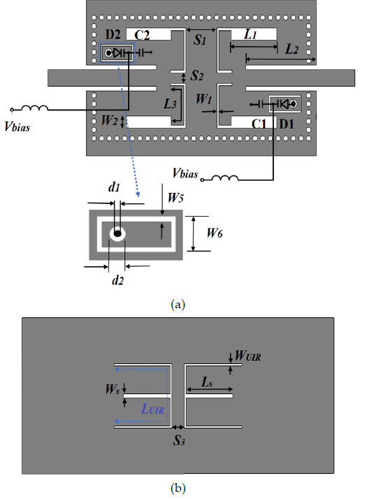
Top and the bottom views of the proposed tunable dual-mode SIW-based BPF are displayed in Figure 1(a) and Figure 1(b).
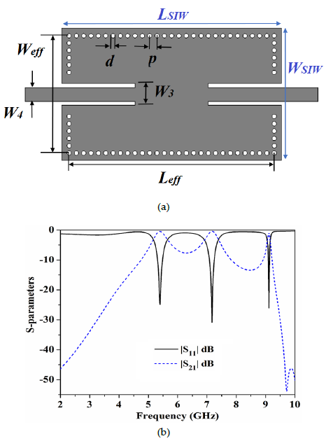
As shown in Figure 2(a), a SIW cavity is initially designed. The fundamental frequency of resonance of the proposed cavity is designed at 5.3 GHz [1]. The cavity resonance is kept a little high to minimize the area requirement. In Figure 2(b) the S-parameters of the simulated SIW cavity are illustrated. It can observe that the fundamental frequency of the resonator is 5.3 GHz. Up to 10 GHz, there are two spurious frequencies centered at 7.1 GHz and 9.1 GHz.
On top of the SIW cavity, stepped impedance resonators (SIRs) are placed to achieve dual-mode features and mitigate spurious frequency ranges. Inset in Figure 3 highlights the open-ended SIR’s configuration. The SIR is made up of electrical sections Z1 and Z2 with corresponding electrical lengths of θ1 and θ2, and high and low impedance portions Z1 and Z2, respectively. An essential factor in modifying the SIR features is RZ = (Z2/Z1). The SIR input admittance is derived as:
$$Y_{in} = jY_2 \frac{Z_2 + Z_1 \cot \theta_1 \tan \theta_2}{Z_1 \cot \theta_1 – Z_2 \tan \theta_2}\tag{1}$$
The resonance condition is determined considering Yin=0. Figure 3 plots the ratio of normalized first spurious frequency (f1) and fundamental frequency (f0) for various impedance ratios (Rz), to easily extract the design parameters. To achieve the dual mode characteristics, fundamental resonant frequency is maintained at 4.5 GHz. The first spurious of SIR is predicted to be at 10.8 GHz, for a spurious free response up to 10 GHz. For fundamental frequency and the first spurious , the SIR has an impedance ratio of 0.57. Z2 has a 60 Ω impedance, and its corresponding electrical length, θ2 is 680. The high impedance section’s computed impedance Z1 is 113Ω with an electrical length of 880. The dimensions of low impedance part has 7 mm in length, 1.4 mm in width, and for high impedance part are 9.3 mm and 0.3 mm, respectively.
Finally, the topmost surface of the cavity is etched with the SIR structure. For symmetry reasons, four SIRs are etched into the SIW cavity as, displayed in the inset of Figure 4(a). The classical filter design methods are adopted [14] to meet the design specification for n79 band (4.4-5.0 GHz), of 5G New Radio (NR). The circuit’s coupling coefficient (k) and external quality factor (Qe) components of a prototype lowpass filter is determined in order to develop the proposed filter. The Qe and k for any designed filter can be calculated as provided in [13]. Figure 4(a) shows the Qe and k for different separations S1. It can be observed that the higher value of Qe can be obtained by increasing the S1. The value of k can also be significantly controlled by S1. It can be inferred that the higher value of k can be achieved by reducing S1. To facilitate the design procedure, the value of Qe and k is required to find for the proposed filter. For the required passband from 4.4 GHz to 5.0 GHz the value of Qe is 10.2 whereas the calculated value of k is 0.075. To accomplish the required Qe and k the S1 is determined to be 4.2 mm. The value of S1 is revised further and selected to be 4.0 mm.

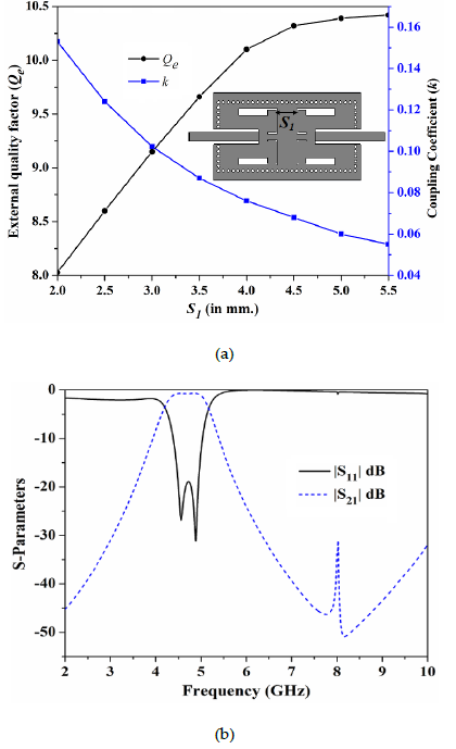
Figure 4 (b) depicts the simulated filter S-parameters. It is clear that the suggested filter results in a dual-mode characteristic with a passband ranging from 4.4 GHz upto 5 GHz. Through the passband, the S21 is better than -0.3 dB and the S11 value is less than -19.0 dB. Additionally, it can be seen that the SIR’s presence suppresses the spurious bands. The upper stopband response is satisfactory with attenuation levels greater than 30 dB are achieved up to 10 GHz.
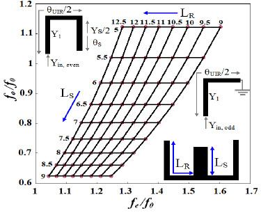
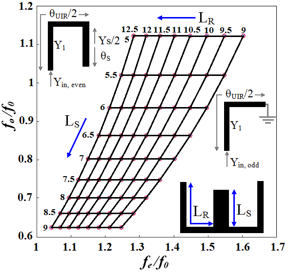
Figure 4(b) inferred that the selectivity of the filter is poor. Therefore, to increase the selectivity, two E-shaped resonators are introduced in the ground plane. The basic -shaped stub structure is displayed in inset of Figure 5. A uniform impedance resonator (UIR) with electrical length θUIR and admittance Y1 is used to realize the resonator. A stub of electrical length θS and admittance YS is loaded into the center of the resonator. The input admittance is derived as follows for even and odd modes.
$$Y_{in,\ odd} = -jY_1 \cot\left(\frac{\theta_{UIR}}{2}\right)
\tag{2}$$
$$Y_{in,\ even} = jY_1 \frac{Y_s \tan(\theta_s) + 2Y_1 \tan\left(\frac{\theta_{UIR}}{2}\right)}{2Y_1 – Y_s \tan(\theta_s) \tan\left(\frac{\theta_{UIR}}{2}\right)}
\tag{3}$$
The resonance condition can be determined by setting Yin,odd=0, and Yin,even=0. Resonating modes fo and fe are extracted by assuming Y1=Ys/2. Figure 5 shows the normalized odd and even modes of resonant frequency for different values of LR and LS. The E-shaped resonator is designed to form two modes at 4.0 GHz and 6.0 GHz. From the plot, it can be observed that the fo is fully depends on LR whereas the fe can be controlled by LR and LS. The calculated value of LR and LS is tuned further to improve the performance. The resonating frequencies are chosen to improve the selectivity. For LR and LS, optimal values are 10.5 mm and 6.0 mm, respectively. In order to generate a considerable degree of attenuation at the appropriate frequency, the inter-resonator spacing (S3) is adjusted.
2.1. Reconfigurable Bandpass Filter Design
In order to achieve the tunable characteristics, the proposed dual-mode BPF is loaded with two surface-mounted varactor diodes diagonally. Figure 1 depicted the proposed tunable bandpass filter where two SMV (1232-079LF and two DC blockers (C0603C330K5RACTU) are used. The anode terminal of the varactor diode is connected to the ground using a metallic post. The cathode terminal is landed on a rectangular island where bias voltage is applied. The diodes D1 and D2 are connected to the cavity through the two DC blockers C1 and C2 respectively. Through a 27 nH inductor, the bias voltage is applied to the varactor diode.
3. Measured Results and Discussion
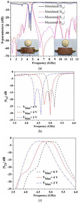
The fabricated prototype is displayed in Figure 6(a) as inset. The EM-simulated and measured S-parameters are compared in Figure 6(a). It can be seen that with the bias voltage Vbias=3V, the proposed filter gives a measured passband from 4.42 to 5.03 GHz. The measured S11 is less than -12.0 dB throughout the passband, while the measured S21 is better than -2.1 dB. Further observations include the suppression of spurious bands and the presence of two transmission zeros at frequencies of 3.85 GHz and 6.35 GHz. This improves the selectivity of the proposed filter. Three more number of transmission zeroes can be observed at 10.8 GHz, 11.7 GHz, and 12.6 GHz which increases the stopband range. More than 17 dB attenuation level is witnessed up to 13 GHz. Figure6(b) and 6(c) shows the |S11| and |S21| simulated results of the proposed tunable bandpass filter. By varying, the bias voltage of the varactor diode, which ranges from 2 to 6 V, the filter’s center frequency can be tuned. Where can be observed, the passband center frequency can be moved from 4.5 GHz to 5.1 GHz as the reverse bias voltage rises. Over a bandwidth of 600 MHz structure is tuned. Throughout the tuning range, S11 is below -12 dB, and the S21 is better than -2.1 dB with excellent selectivity. Overall size of the filter is 30 18 mm2. A comparative analysis is presented in Table 1 with previously published works. It can be observed that the proposed filter has better insertion loss compared to the work reported in [9] and [12]. The proposed filter has accomplished better stopband range and better fractional bandwidth compared to the filters presented in [7], [9], [10] and [12]. The filter structure exhibits a compact size compared to the filter reported in [7], [9] and [10]. The skirt factor, which is defined as the ratio of the passband’s 3 dB bandwidth to its 20 dB bandwidth, is presented in order to explain selectivity. The skirt factor is 0.44 for the proposed filter which better compared to the filters presented in [7], [9], [10] and [12].
4. Conclusion
This manuscript presents a novel tunable dual-mode bandpass filter using SIW cavity. Etching SIRs into the top surface of the SIW cavity results in the dual-mode passband and a wide upper stopband performance. E-shaped resonators in the ground plane improve the selectivity. The resonating structures are properly analyzed and the resonating frequencies are determined. The tunable characteristic is achieved by employing two varactor diodes with good return loss and wide tuning range. The filter has compact size, low insertion loss, excellent selectivity, and wide upper stopband characteristics which are useful for modern communication systems.
Table 1: Performance comparison with some SIW based bandpass filter
Ref. | Response | Tunable | Center Frequency (f0 GHz) | FBW (%) Fractional Bandwidth | RL(dB) Return Loss | IL(dB) Insertion Loss | Skirt Factor | Stopband frequency (a× f0) | Stopband attenuation (dB) | Size ((𝝀𝒈×𝝀𝒈) |
[7] | SIW BPF | No | 13/13.2 | 4.6/4.5 | 15/10 | 1.7/1.5 | 0.4/0.35 | (2f0) /(2.2 f0) | 20/20 | 0.9316 |
[9] | Dual-Mode BPF | No | 10 | 5.3 | 18 | 2.4 | 0.34 | 1.05 f0 | 30 | 1.75 |
[10] | Dual-mode Dual-Band BPF | Yes | 17/19.36 | 2.01/4.1 | 17 | 2.1/1 | 0.38/0.18 | (1.05f0) /(1.13 f0) | 20/20 | 2.62 |
[12] | Dual-Band BPF | Yes | 2.25/4.5 | 13.33/8.8 | 15/17 | 2.33/3.38 | 0.25/0.25 | (1.42f0) /(1.33 f0 | 20/20 | 0.04 |
This work | Dual-Mode BPF with wide upper stopband characteristics | Yes | 4.7 | 14.89 | 12 | 2.1 | 0.43 | (2.85 f0) | 17 | 0.44 |
𝜆𝑔 is the guided wavelength derived at the passband’s center frequency passband, RL stands for Return Loss, IL for Insertion Loss, and FBW for Fractional Bandwidth.
- D. Deslandes and K. Wu, “Single-substrate integration technique of planar circuits and waveguide filters,” IEEE Transactions on Microwave Theory and Techniques, vol. 51, no. 2, pp. 593-596, 2003, doi: 10.1109/TMTT.2002.807820.
- A. Parameswaran and S. Raghavan, “Novel siw dual mode band pass filter with high skirt selectivity,” 2nd International Conference for Convergence in Technology (I2CT), 2017, pp. 189-191, doi: 10.1109/I2CT.2017.8226118.
- M. Almalkawi, M. Westrick, V. Devabhaktuni, M. Alam, L. Zhu and J. Deng, “Design of a dual-band dual-mode substrate integrated waveguide filter with symmetric transmission zeros,” IEEE Applied Electromagnetics Conference (AEMC), 2011, pp. 1-3, doi: 10.1109/AEMC.2011.6256872.
- H. Zhang, W. Kang and W. Wu, “Miniaturized Dual-Band SIW Filters Using E-Shaped Slotlines With Controllable Center Frequencies,” IEEE Microwave and Wireless Components Letters, vol. 28, no. 4, pp. 311-313, 2018, doi: 10.1109/LMWC.2018.2811251.
- S. Xu, K. Ma, F. Meng and K. S. Yeo, “Novel Defected Ground Structure and Two-Side Loading Scheme for Miniaturized Dual-Band SIW Bandpass Filter Designs,” IEEE Microwave and Wireless Components Letters, vol. 25, no. 4, pp. 217-219, 2015, doi: 10.1109/LMWC.2015.2400916.
- S. Wang, D. Zhang, Y. Zhang, L. Qing and D. Zhou, “Novel Dual-Mode Bandpass Filters Based on SIW Resonators under Different Boundaries,” IEEE Microwave and Wireless Components Letters, vol. 27, no. 1, pp. 28-30, 2017, doi: 10.1109/LMWC.2016.2629963.
- D. Jia, Q. Feng, Q. Xiang and K. Wu, “Multilayer Substrate Integrated Waveguide (SIW) Filters With Higher-Order Mode Suppression,” IEEE Microwave and Wireless Components Letters, vol. 26, no. 9, pp. 678-680, 2016, doi: 10.1109/LMWC.2016.2597222.
- M. A. Rahman and P. Sarkar, “A Novel Compact Dual-Mode Substrate Integrated Waveguide Cavity based Bandpass Filter for WLAN Applications,” International Conference on Computational Performance Evaluation (ComPE), 2020, pp. 059-061, doi: 10.1109/ComPE49325.2020.9200038.
- F. Zhu, G. Q. Luo, Z. Liao, X. W. Dai and K. Wu, “Compact Dual-Mode Bandpass Filters Based on Half-Mode Substrate-Integrated Waveguide Cavities,” IEEE Microwave and Wireless Components Letters, vol. 31, no. 5, pp. 441-444, 2021, doi: 10.1109/LMWC.2021.3066569.
- M. F. Abbas, and A. J. Salim, “A New Tunable Dual-Mode Dual-Band Square Cavity SIW Bandpass Filter,” Progress In Electromagnetics Research C, vol. 118, pp. 113-123, 2022, doi:10.2528/pierc21120306
- M. Abdelfattah, R. Zhang and D. Peroulis, “High-Selectivity Tunable Filters With Dual-Mode SIW Resonators in an L-Shaped Coupling Scheme,” IEEE Transactions on Microwave Theory and Techniques, vol. 67, no. 12, pp. 5016-5028, 2019, doi: 10.1109/TMTT.2019.2944365.
- C. X. Zhou, C. M. Zhu and W. Wu, “Tunable Dual-Band Filter Based on Stub-Capacitor-Loaded Half-Mode Substrate Integrated Waveguide,” IEEE Transactions on Microwave Theory and Techniques, vol. 65, no. 1, pp. 147-155, 2017, doi: 10.1109/TMTT.2016.2613053.
- 5G NR specifications, document TS 38.101-1 V15.4.0 3GPP Release15, Dec. 2018.
- J. S. G. Hong, and M. J. Lancaster, “Microstrip filters for RF/microwave applications,”John Wiley & Sons, 2004.
No related articles were found.