Missile Guidance using Proportional Navigation and Machine Learning
(This article belongs to the Special Issue on Special Issue on Computing, Engineering and Sciences (SI-CES 2023-24) and the Section Aerospace Engineering (ARO))
Export Citations
Cite
Hodžić, M. and Prljača, N. (2024). Missile Guidance using Proportional Navigation and Machine Learning. Journal of Engineering Research and Sciences, 3(3), 19–26. https://doi.org/10.55708/js0303003
Mirza Hodžić and Naser Prljača. "Missile Guidance using Proportional Navigation and Machine Learning." Journal of Engineering Research and Sciences 3, no. 3 (March 2024): 19–26. https://doi.org/10.55708/js0303003
M. Hodžić and N. Prljača, "Missile Guidance using Proportional Navigation and Machine Learning," Journal of Engineering Research and Sciences, vol. 3, no. 3, pp. 19–26, Mar. 2024, doi: 10.55708/js0303003.
Variants of proportional navigation (PN) are perhaps mostly used guidance laws for tactical homing missiles. PN aims to generate commanding missile lateral acceleration proportional to line of sight (LOS) angular rate, so that missile velocity vector rotates in such a way to assure interception of a target. In order to generate commanding lateral accelerations, the guidance system needs measurements of LOS angular rate and the closing velocity between the missile and the target, or the missile velocity. A device which provides guidance information is referred to as the missile seeker. In the case of imaging based seekers (visible light (EO), infrared light (IIR)), LOS rate is estimated using imaging sensor, while closing or missile velocity is measured using appropriate sensors or guess estimated. In this paper, we present the design and simulation of a missile homing system which includes: true PN guidance law, linear multiloop acceleration autopilot, and gimbaled imaging based missile seeker. Target seeker uses advanced deep machine learning object detection YOLO (You only look once) model, for target detection and tracking as well as LOS rate estimation. Comprehensive simulation model, consisting of full 6DOF missile and controls dynamics, 3D world and camera model, is developed. Intensive simulation results show performances of the proposed missile homing system.
1. Introduction
Many missile guidance and control laws have been developed in the past. Reported missile autopilot designs have ranged from classical linear to the most advanced ones [1]–[4]. The most widely used guidance law among them is a variant of proportional navigation(PN) [5]–[8]. Homing missiles using a variant of proportional navigation (PN) guidance law require measurement of LOS angular rate and measurement of closing velocity or missile velocity. This implies that missile seeker is able to detect and track targets during engagement. In active homing missiles, radar based missile seeker is used to detect the target, track the target and measure LOS rate and closing velocity. In passive homing missiles, strap-down or gimbaled imaging sensor (EO/IIR) based missile seeker is used to detect the target, track the target and estimate LOS angular rate, while missile velocity is measured with an appropriate sensor (IMU). In this work, a two axis (pitch and yaw) gimbal carrying an imaging device keeps the target in the camera field of view (FOV) by means of a gimbal control tracking loop. Accurat among them is the YOLO (You only look once) family [9]. This work investigates application of YOLO deep machine learning object detector for tracking error measurements and consecutive LOS angular rate estimation in missile seeker. YOLO performance assessment in guidance loop is realized by means of a comprehensive Matlab/Simulink simulator, which includes nonlinear 6DOF missile and controls dynamics as well as 3D world (scene) and imaging models. This work was motivated by the fact, that to the best of the authors knowledge, no published work has been found which deals with similar simulation study.
2. Missile 6-DOF dynamic model
In order to simulate missile guidance, a high-fidelity non- linear model is needed. Cruciform missile can be modeled as a rigid body which is governed by a system of coupled nonlinear first order differential equations with constant coefficients:
$$\dot{P} = \frac{L}{I_x} \tag{1}$$
$$\dot{Q} = \frac{PR(I_z – I_x)}{I_y} + \frac{M}{I_y} \tag{2}$$
$$\dot{R} = \frac{PQ(I_x – I_y)}{I_z} + \frac{N}{I_z} \tag{3}$$
$$\dot{u} = vR – wQ + \frac{F_x}{m} \tag{4}$$
$$\dot{v} = wP – uR + \frac{F_y}{m} \tag{5}$$
$$\dot{w} = uQ – vP + \frac{F_z}{m} \tag{6}$$
Where u, v and w are missile velocities along x, y and z axes of the missile body frame. P, Q and R are rotational angular velocities about x, y and z axes of the missile body frame. Fx, Fy and Fz are forces which are acting along the respected body axes and L, M and N are moments which are acting along the respected body axes. Ix, Iy and Iz are moments of inertia about the missile body axes. Inertia cross products are zero since the missile airframe is symmetric. For a cruciform missile, aerodynamic forces can be approximated as follows [10]:
$$\left[\begin{array}{c} F_x \\ F_y \\ F_z \end{array}\right] = \left[\begin{array}{c} C_{x_0} + C_{x_2}(\alpha^2 + \beta^2) \\ C_N \beta \\ C_N \alpha \end{array}\right] \tag{7}$$
Total force on acting along the missile body axes can:
$$\begin{bmatrix} F_x \\ F_y \\ F_z \end{bmatrix} = \begin{bmatrix} T \\ 0 \\ 0 \end{bmatrix} + mg \begin{bmatrix} -\sin\theta \\ \sin\phi\cos\theta \\ \cos\phi\cos\theta \end{bmatrix} – qS \begin{bmatrix} C_{x_0} + C_{x_2} \left( \alpha^2 + \beta^2 \right) \\ C_N \beta \\ C_N \alpha \end{bmatrix} \tag{8}$$
Where q = ρv2m /2 is the dynamic pressure, q is the density of air at given altitude and vm is the total velocity of the missile. The gravitational force is naturally given in earth reference frame so it has to be transformed to body axes frame. In the previous equation, Cx0 and CN are aerodynamic coefficients calculated at the various angles of attack α and sideslip an- gles β. Angle of attack and sideslip angle can be calculated as follows:
$$\alpha = \arctan\frac{w}{v} \tag{9}$$
$$\beta = \arctan\frac{v}{u} \tag{10}$$
Furthermore, it is important to define Euler RPY angles which describe the orientation of the missile with respect to the inertial reference frame. Euler angles can be integrated from the following equation:
$$\begin{bmatrix} \dot{\phi} \\ \dot{\theta} \\ \dot{\psi} \end{bmatrix} = \begin{bmatrix} 1 & \sin\phi \tan\theta & \cos\phi \tan\theta \\ 0 & \cos\phi & -\sin\phi \\ 0 & \frac{\sin\phi}{\cos\theta} & \frac{\cos\phi}{\cos\theta} \end{bmatrix} \begin{bmatrix} P \\ Q \\ R \end{bmatrix} \tag{11}$$
Moments acting on the missile are a consequence of rota- tion of actuator surfaces and of forces acting on the missile. Aerodynamic forces are acting on the point called the center of pressure, while the gravitational force is acting on the center of gravity of the missile. This causes a moment which rotates the missile. Therefore, the missile moments can be calculated as follows:
$$\begin{bmatrix} L \\ M \\ N \end{bmatrix} = \begin{bmatrix} 0 \\ -r_X F_{AZ} \\ r_X F_{AY} \end{bmatrix} + \frac{qS}{v_m} \begin{bmatrix} C_{LP} P \\ C_{MQ} Q \\ C_{NR} R \end{bmatrix} + qS \begin{bmatrix} C_{L\delta_E} \delta_E \\ C_{M\delta_V} \delta_V \\ C_{N\delta_P} \delta_P \end{bmatrix} \tag{12}$$
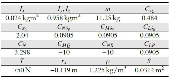
In the previous equation, rx is the distance between center of gravity and center of pressure and FAY and FAZ are aeordynamic forces acting along the missile body axes. CLP, CMQ and CNR are rolling, pitching and yawing aerodynamic coefficients respectively. CLδE , CLδV and CLδP are aerodynamic coefficients with respect to the angular displacement of actuator surfaces denoted by δE, δV and δP. Table 1 shows used missile parameters [11].
Table 1: Missile parameters
3. Proportional navigation
The basic intuition of proportional navigation(PN) [12] is to generate commanding lateral accelerations which are proportional to the line of sight rate (LOS) angular rate as follows:
$$a_c = N \dot{\nu}_c \tag{13}$$
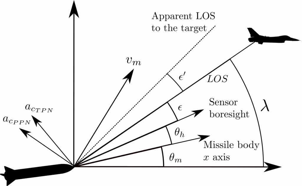
Where ac is the commanded lateral acceleration normal to the line of sight, N ≥ 2 is the effective navigational ratio and vc is the relative velocity between the missile and the target. These commanded accelerations are then forwarded to the autopilot which makes sure that the missile achieves these lateral accelerations. In recent works, authors simulated this guidance method on 6-DOF missile simulator in Matlab in [13] and [14]. For even more insight into missile guidance and control, the reader is referred to [10], [11], [15]–[21]. As is shown in figure 1, in order to calculate λ or λ˙ it is needed to measure relative distance and relative velocity between the missile and the target.
Unfortunately, these values cannot be measured without an active radar which most tactical missiles do not have. Similarly, the closing velocity vc cannot be measured without an active radar. That is why this article implements another variant of PN called the pure proportional navigation whose commanding accelerations are normal to the missile velocity [12] and are given by:
$$a_c = N \dot{\lambda} v_m \tag{14}$$
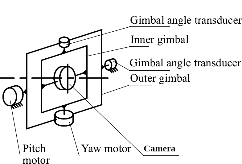
Missile seeker is the device that has to measure LOS rate. The seeker is made out of two independent gimbal axes, two servo motors and an imaging (EO/IIR) sensor. These two gimbals move across the vertical and the horizontal plane in order to lock onto the target. Once locked, the seeker can measure the tracking error, which is noted with ϵ in figure 1. Earlier work [14], [22]–[25] explain in great detail on how to obtain LOS and LOS rate from the measured tracking error. The LOS angular rate in vertical plane can be obtained using the following equation:
$$\dot{\lambda}_{zm} = \epsilon_z \frac{s}{\tau s + 1} + \dot{\theta}_h + \dot{\theta}_m \tag{15}$$
Where θm is the Euler pitch angle of the missile relative to the inertial frame of reference, θh is the angular position of the gimbal servo relative to the missile centerline in vertical plane and ϵz is the measured tracking error in the vertical plane. Angular velocity θ˙m is easy to obtain using rate gyro as is explained in [14] and θ˙h has to be calculated from measured angular rates around the body axes as is explained in [13]. Similar to equation 15, LOS rate in the horizontal plane can be obtained as follows:
$$\dot{\lambda}_{ym} = \epsilon_y \frac{s}{\tau s + 1} + \dot{\psi}_h + \dot{\psi}_m \tag{16}$$
the inertial frame of reference, ψh is the angular position of the gimbal servo relative to the missile centerline in the horizontal plane and ϵy is the measured tracking error in the horizontal plane. Most tactical missiles have infrared homing seeker. Because of this, tracking error cannot be measured directly but it is assumed to be indicated angular position of the target relative to the camera centerline or boresight [10]. This paper aims to simulate a seeker sensor which utilizes Matlab 3D camera, which would measure the tracking error from obtained images. Matlab interface for Unreal Engine allows simulations of 3D vehicles as well as taking images from Unreal Engine world. Also, implementation, simulation and control of gimbal servo system are presented in this article since it is guidance requirement to keep the tracking error as low as possible.
4. Autopilot design
If the missile lateral accelerations are exactly equal to the commanded accelerations commanded by the guidance subsystem, then the interception is guaranteed. Missile sub- system which will ensure this is referred to as the autopilot. From the missile dynamic model, it can be shown that there will be no cross-coupling between yaw and pitch motion if the missile is not rolling. Therefore, it is imperative that the autopilot ensures zero roll angle of the missile. Once that is achieved, motion in yaw and pitch plane can be controlled independently. Therefore, it is enough to implement three PID controllers. One PID controller to ensure roll stability and two PID controllers for two lateral accelerations. Figure 2 shows a roll controller design.
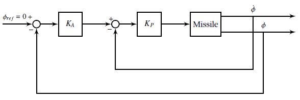
Roll controller employs a cascade error regulation. The inner loop which feeds back roll derivative is a damping loop which ensures minimum oscillations in the roll channel. In order to achieve lateral acceleration tracking, an expression for calculating lateral acceleration is needed. In order to calculate them, a derivative of a rotating vector is needed and that vector has to be transformed into coordinate system whose x-axis coincides with the velocity vector. Such coordinate system is also called the wind frame. Therefore, accelerations in the wind frame are given by:
$$\begin{bmatrix} a_x \\ a_y \\ a_z \end{bmatrix} = \begin{bmatrix} \cos\alpha\cos\beta & -\sin\beta & \sin\alpha\cos\beta \\ \sin\beta\cos\alpha & \cos\beta & -\sin\alpha\sin\beta \\ -\sin\alpha & 0 & \cos\alpha \end{bmatrix} \left( \begin{pmatrix} \dot{u} \\ \dot{v} \\ \dot{w} \end{pmatrix} + \begin{bmatrix} P \\ Q \\ R \end{bmatrix} \times \begin{bmatrix} u \\ v \\ w \end{bmatrix} \right) \tag{17}$$
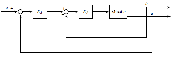
Where ay and az are missile horizontal and vertical acceleration components normal to the velocity vector and ax is the missile acceleration component along the velocity vector. This acceleration is usually zero since the missile does not have any fuel left during the terminal guidance phase. Figure 3 shows a controller for lateral accelerations. Similar design for horizontal and vertical acceleration components is employed. The inner loop reduces response oscillations and the outer loop ensures that the lateral acceleration follows the demanded lateral acceleration.
Missile aerodynamics coefficients change with respect to the Mach number, angle of attack, angle of sideslip, altitude and angular velocities, so it might be advisable to design multiple controllers for various operating points. This approach is referred to as gain scheduling [26, 27]. In his article fixed gain linear (PD) controllers are used regardless of missile homing operational conditions, due to their simplicity and robustness.
5. YOLO neural network
In order to calculate the tracking errors ϵy and ϵz, it is first required to localize object in the image. Furthermore, it is needed to classify the object in the obtained image. There is a handful of requirements that the localization algorithm has to satisfy in missile guidance applications. First, during simulations images are obtained from Unreal Engine environment so the algorithm must be able to work with artificial images. Second, the algorithm has to be very fast since camera can generate images with very high frequency. Most suitable localization algorithm in this case is You Only Look Once(YOLO) convolutional neural network. YOLO was first introduced in 2016 where object detection was reframed as a single regression problem straight from image pixels to bounding box and class probabilities [9]. This made sure that YOLO needed only one passage through the network to obtain localization result which made it much faster then existing algorithms which were based on region proposals. Over time, a number of object detectors based on YOLO were developed. Most notably, YOLO9000 [28], YOLOv3 [29] and YOLOv4 [30] and YOLOv8 [31]. This article uses YOLOv4 since it is latest available in Matlab. YOLOv4 in Matlab is pretrained on Common Objects in Context(COCO) dataset [32] which consists of 80 classes and over 330000 images.
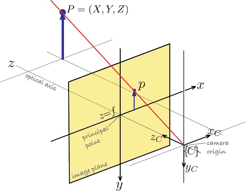
Let X and Y denote the object size and let x and y denote size of the image in the image plane. Let fx and fy denote horizontal and vertical focal length measured in pixels which is also the distance of image plane from the CCD sensor, Inspecting Figure 4, it can be seen that tracking error angle in vertical plane can be evaluated as follows:
$$\epsilon_z = \arctan{\frac{y}{f_y}} \tag{18}$$
For vertical tracking error angle, the equation is analogous:
$$\epsilon_y = \arctan{\frac{x}{f_x}} \tag{19}$$
It is straightforward to implement calculation of the tracking errors. YOLO detector can obtain bounding box around the detected target with coordinates of the upper left corner(denoted with xt and yt) and its width and height(denoted with w and h). Now expressions for vertical and horizontal tracking errors are as follows:
$$\epsilon_z = \arctan{\frac{y_t + h/2}{f_y}} \tag{20}$$
$$ \epsilon_y = \arctan{\frac{x_t + w/2}{f_y}} \tag{21}$$
7. Seeker camera gimbal servo controls
The camera is mounted on the head of the missile and it can rotate about the vertical and the horizontal axes on gimbal (yaw, pitch) using two DC motors. Rotational motions of these two motors is independent. Figure 5 shows mechanical structure of a missile seeker.
The goal of these DC motor based servo systems is to nullify the tracking error so that the target is always at the center of the obtained image. Therefore, the target tracking problem can be viewed as a control problem where the tracking error is considered an output value with desired reference value equal to zero. This way, radome refraction error is minimized and better measurements are available. It is important to note that the gimbal servo control systems have to be sufficiently fast in order to quickly eliminate tracking errors. The servo motor can be modeled as a second order linear system as follows:
$$G(s) = \frac{\omega_n^2}{s(s + 2\xi\omega_n)} \tag{22}$$
Where ξ and ωn are damping coefficient and system angular frequency respectively. The tracking loop dynamics bandwidth is very wide, usually about 100 rad/sec [10]. A standard PID controller is used for each gimbal axis. The controllers are tuned so that they achieve acceptable settling time and overshoot.
8. Missile guidance system synthesis
Each previous section presents a single part of the missile guidance system. The typical missile guidance system consists of guidance system, missile seeker, autopilot and the missile itself. Figure 6 shows the block diagram of the missile guidance system.
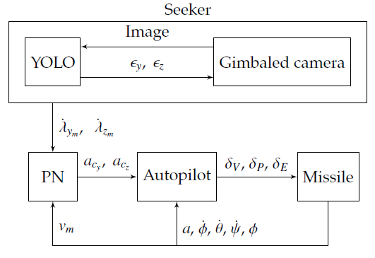
Missile guidance systems design showed in the figure 6 only measures the image of the target. The remaining measurements can be obtained from the missiles internal sensors. Missile linear and angular velocities can be measured using inertial measurement units (IMU), from which Euler angles and their derivatives can be obtained using sensor fusion technique. Gimbal angles are measured by appropriate angle transducers.
9. Simulation
Previously described missile guidance system was implemented in Matlab and Simulink implementing previously described equations. Missile and the target position and orientation are fed into Unreal Engine blocks. Matlab offers Simulation 3D camera block to obtain images from the Unreal Engine scene. Simulation 3D camera block outputs an image which is fed to the YOLO block(implemented as a Matlab system) which calculates tracking errors given by equations 18 and 19. Camera generates 100 frames per second(fps) which is fast enough to capture tracking error dynamics. Obtained tracking errors are then fed into two PID controllers as error inputs. Controller outputs are fed into gimbal systems as inputs and gimbal positions are fed into camera as inputs to rotate the camera relatively to the missile body. Based on the equation 15, the seeker subsystem estimates the line of sight angular rate in the vertical and the horizontal plane. Subsystem for proportional navigation calculates the required lateral accelerations in vertical and horizontal plane. The autopilot subsystem calculates required elevator, rudder and aileron deflections.
Figure 7 shows trajectories of the target and the missile during the terminal guidance phase. The target is at the initial relative height of 200 meters and an initial relative distance of 500 meters. The target is escaping with the velocity 100m/s and moving sideways with the velocity 20m/s. It can also be seen that the missile is aiming at future intercept point rather than following the target. This means that PN requires lower commanded acceleration comparing to more traditional guidance methods.
Figure 8 shows one frame which is processed by YOLO detection algorithm. Here it can be seen that YOLO finds the bounding box around the object and that the object is in the center of the image.
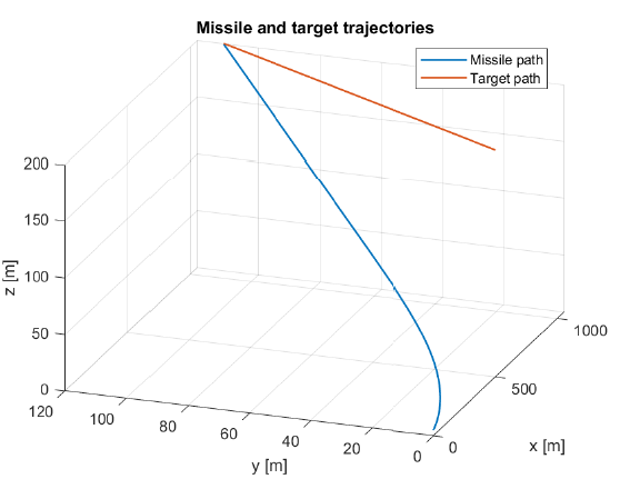

Figure 9 shows obtained tracking errors. It can be seen that there are some initial oscillations due to the target moving which can be interpreted as output disturbances in the tracking errors.
Figures 10 and 11 show estimated and real LOS rates in the vertical and the horizontal plane respectively. It can be seen that the seeker estimates LOS rates fairly quickly and that they approach zero as the distance shortens which is a requirement for interception.
Figure 12 shows the missile Euler angles. It can be seen that the roll angle is always zero because the roll controller stabilizes the missile roll channel. The autopilot steers the missile so the missile has to keep an almost constant yaw and pitch angle in order to achieve a hit.
Figures 13 and 14 show commanded and achieved lateral accelerations. It can be seen that the autopilot subsystem ensures that the missile lateral accelerations are equal to the demanded PN accelerations.
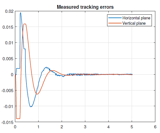
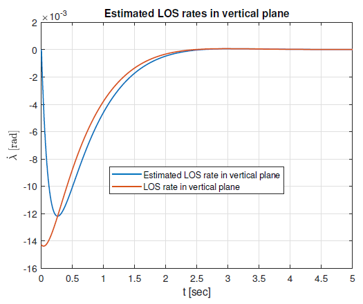
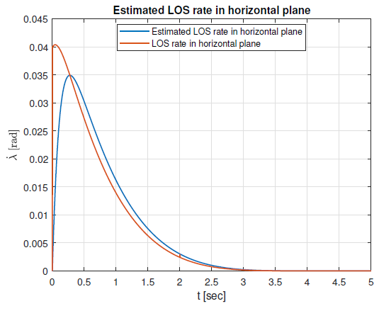
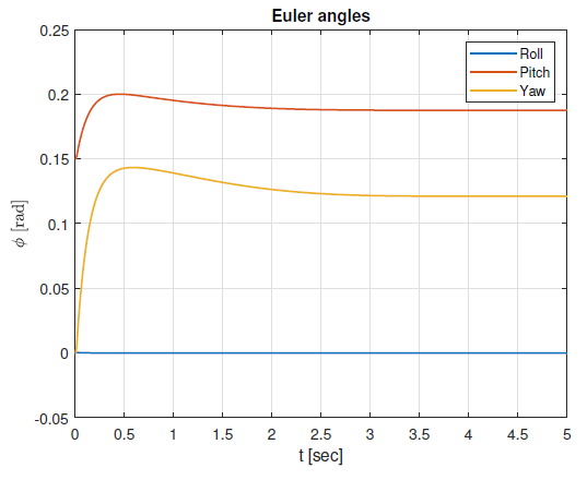
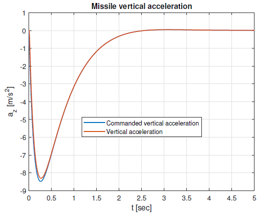
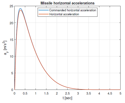
Table 2: Missile performance table
6. Performance analysis
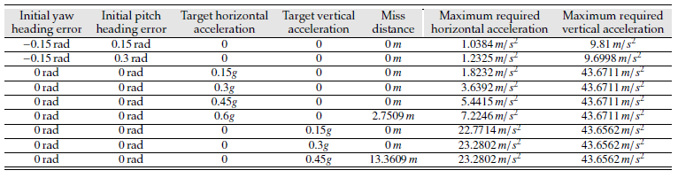
Proportional navigation can guarantee interception of a target moving with constant velocity. If the target is maneuvering or accelerating, there can be nonzero miss distance. Proportional navigation can ensure interception even if there is an initial heading error, although this requires the missile to have more energy available and larger demanded accelerations. Table 2 shows performance for various heading errors and target accelerations. Final miss distance and maximum required accelerations are chosen as a measure of performance. It can be seen that proportional navigation can nullify the miss distance due to the initial heading error given that the missile can achieve demanded lateral acceleration. If the target is accelerating, the proportional navigation may not be able to nullify the miss distance.
11. Conclusion
This article presents design and simulation of missile homing system. The missile homing system consist of guidance law, autopilot and imaging based target tracking subsystem (missile seeker). In this work the guidance law is based on true proportional navigation. Autopilots stabilize roll angle and regulate horizontal and vertical accelerations. They are standard linear multi loop controllers. Two axes (pitch, yaw) gimbaled seeker use standard PID controllers to track the target. The seeker uses state-of-art deep ma- chine learning YOLO (You Only Look Once) object detector for tracking error measurements and LOS rate estimation. Comprehensive homing missile simulator is developed, and simulation results show robust accuracy of the proposed scheme to target velocity, launch heading errors and low level target maneuvering. Our future research work will focus on design and simulation of advanced guidance and control laws, as well as design and simulation of advanced machine learning algorithms.
- M. Abd-elatif, L. jun Qian, Y. ming Bo, “Optimization of three- loop missile autopilot gain under crossover frequency constraint”, “Defence Technology”, vol. 12, no. 1, pp. 32–38, 2016, doi:10.1016/j.dt.2015.08.006.
- B. Zhang, Q. Lv, Y. Lei, “The application of pid controller in mis- sile longitudinal loop system and its simulation”, “Proceedings of the 5th International Conference on Advanced Design and Manufac- turing Engineering”, pp. 2113–2118, Atlantis Press, 2015/10, doi: 10.2991/icadme-15.2015.395.
- A. Awad, H. Wang, “Roll-pitch-yaw autopilot design for nonlinear time-varying missile using partial state observer based global fast ter- minal sliding mode control”, “Chinese Journal of Aeronautics”, vol. 29, no. 5, pp. 1302–1312, 2016, doi:https://doi.org/10.1016/j.cja.2016.04. 020.
- A. Thukral, M. Innocenti, “A sliding mode missile pitch autopilot synthesis for high angle of attack maneuvering”, “IEEE Transactions on Control Systems Technology”, vol. 6, no. 3, pp. 359–371, 1998, doi: 10.1109/87.668037.
- C.-D. Yang, C.-C. Yang, “A unified approach to proportional naviga- tion”, “IEEE Transactions on Aerospace and Electronic Systems”, vol. 33, no. 2, pp. 557–567, 1997, doi:10.1109/7.575895.
- S. A. Murtaugh, H. E. Criel, “Fundamentals of proportional nav- igation”, “IEEE Spectrum”, vol. 3, no. 12, pp. 75–85, 1966, doi: 10.1109/MSPEC.1966.5217080.
- M. Guelman, “A qualitative study of proportional navigation”, IEEE Transactions on Aerospace and Electronic Systems, vol. AES-7, no. 4, pp. 637–643, 1971, doi:10.1109/TAES.1971.310406.
- M. Guelman, “Proportional navigation with a maneuvering target”, “IEEE Transactions on Aerospace and Electronic Systems”, vol. AES-8, no. 3, pp. 364–371, 1972, doi:10.1109/TAES.1972.309520.
- J. Redmon, S. Divvala, R. Girshick, A. Farhadi, “You only look once: Unified, real-time object detection”, https://arxiv.org/abs/1506.02640, 2016.
- G. M. Siouris, Missile Guidance and Control Systems, Springer-Verlag New York, 2004.
- J. Harris, N. Slegers, “Performance of a fire-and-forget anti-tank mis- sile with a damaged wing”, “Mathematical and Computer Modelling”, vol. 50, no. 1, pp. 292–305, 2009.
- U. Shukla, P. Mahapatra, “The proportional navigation dilemma-pure or true?”, “IEEE Transactions on Aerospace and Electronic Systems”, vol. 26, no. 2, pp. 382–392, 1990.
- M. Hodžić, N. Prljača, “Simulation of short range missile guidance using proportional navigation”, “2021 20th International Symposium INFOTEH-JAHORINA (INFOTEH)”, pp. 1–6, 2021.
- M. Hodžić, N. Prljača, “Los rate estimation techniques for propor- tional navigation guided missiles”, “2022 21st International Symposium INFOTEH-JAHORINA (INFOTEH)”, pp. 1–6, 2022.
- P. Zarchan, Tactical and Strategic Missile Guidance, no. v. 219 in AIAA Tactical Missile Series, American Institute of Aeronautics and Astro- nautics, 2007.
- R. Yanushevsky, Modern Missile Guidance, Taylor & Francis, 2007.
- N. Shneydor, Missile Guidance and Pursuit: Kinematics, Dynamics and Control, 1, Elsevier Science, 1998.
- M. Drela, Flight Vehicle Aerodynamics, FLIGHT VEHICLE AERODY- NAMICS, MIT Press, 2014.
- S. Graovac, Automatsko vođenje objekata u prostoru, Akademska Misao, 2005.
- C.-F. Lin, Modern Navigation, Guidance and Control Processing, Prentice Hall, 1991.
- M. V. Cook, ed., Flight Dynamics Principles (Third Edition), Butterworth- Heinemann, third edition ed., 2013.
- N. F. Palumbo, R. A. Blauwkamp, J. M. Lloyd, “Basic principles of homing guidance”, “Johns Hopkins Apl Technical Digest”, vol. 29, pp. 25–41, 2010.
- Q. Zaikang, L. Defu, Design of Guidance and Control Systems for Tactical Missiles, CRC Press, 1st ed., 2019.
- S. Mondal, S. Sadhu, A. Banerjee, “Platform motion disturbances attenuation in a missile seeker subsystem using internal model con- trol”, “2013 International Conference on Control, Automation, Robotics and Embedded Systems (CARE)”, pp. 1–4, 2013.
- S. He, Y. Liang, J. Tang, Z. Bai, K. Li, “Homing guidance law design against maneuvering targets based on ddpg”, “International Journal of Aerospace Engineering”, vol. 2023, p. 4188037, 2023.
- D. White, J. Wozniak, D. Lawrence, “Missile autopilot design us- ing a gain scheduling technique”, “Proceedings of 26th Southeastern Symposium on System Theory”, pp. 606–610, 1994.
- A. Hiret, G. Duc, J. Bonnet, “The application of gain-scheduling h controllers for a missile autopilot”, “IFAC Proceedings Volumes”, vol. 31, no. 21, pp. 59–64, 1998, 14th IFAC Symposium on Automatic Control in Aerospace 1998, Seoul, Korea, 24-28 August 1998.
- J. Redmon, A. Farhadi, “Yolo9000: Better, faster, stronger”,
https://arxiv.org/abs/1612.08242, 2016. - J. Redmon, A. Farhadi, “Yolov3: An incremental improvement”,
https://arxiv.org/abs/1804.02767, 2018. - A. Bochkovskiy, C.-Y. Wang, H.-Y. M. Liao, “Yolov4: Optimal speed and accuracy of object detection”, https://arxiv.org/abs/2004.10934, 2020.
- D. Reis, J. Kupec, J. Hong, A. Daoudi, “Real-time flying object detection with yolov8”, 2023.
- T.-Y. Lin, M. Maire, S. Belongie, L. Bourdev, R. Girshick, J. Hays, P. Per- ona, D. Ramanan, C. L. Zitnick, P. Dollár, “Microsoft coco: Common objects in context”, https://arxiv.org/abs/1405.0312, 2015.
- P. Corke, Robotics, Vision and Control – Fundamental Algorithms in MATLAB®, vol. 73 of Springer Tracts in Advanced Robotics, Springer, 2011.