Visual Slam-Based Mapping and Localization for Aerial Images
(This article belongs to the Special Issue on SP1 (Special Issue on Multidisciplinary Sciences and Advanced Technology 2022) and the Section Automation and Control Systems (ACS))
Export Citations
Cite
Eker, O. , Cevikalp, H. and Saribas, H. (2022). Visual Slam-Based Mapping and Localization for Aerial Images. Journal of Engineering Research and Sciences, 1(1), 01–09. https://doi.org/10.55708/js0101001
Onur Eker, Hakan Cevikalp and Hasan Saribas. "Visual Slam-Based Mapping and Localization for Aerial Images." Journal of Engineering Research and Sciences 1, no. 1 (February 2022): 01–09. https://doi.org/10.55708/js0101001
O. Eker, H. Cevikalp and H. Saribas, "Visual Slam-Based Mapping and Localization for Aerial Images," Journal of Engineering Research and Sciences, vol. 1, no. 1, pp. 01–09, Feb. 2022, doi: 10.55708/js0101001.
Fast and accurate observation of an area in disaster scenarios such as earthquake, flood and avalanche is crucial for first aid teams. Digital surface models, orthomosaics and object detection algorithms can play an important role for rapid decision making and response in such scenarios. In recent years, Unmanned Aerial Vehicles (UAVs) have become increasingly popular because of their ability to perform different tasks at lower costs. A real-time orthomosaic generated by using UAVs can be helpful for various tasks where both speed and efficiency are required. An orthomosaic provides an overview of the area to be observed, and helps the operator to find the regions of interest. Then, object detection algorithms help to identify the desired objects in those regions. In this study, a monocular SLAM based system, which combines the camera and GPS data of the UAV, has been developed for mapping the observed environment in real-time. A deep learning based state-of-the-art object detection method is adapted to the system in order to detect objects in real time and acquire their global positions. The performance of the developed method is evaluated in both single and multiple UAVs scenarios.
1. Introduction
Classical 2D image stitching methods that performreal-time mapping from monocular camera in aerial images are built based on feature extraction and matching in consecutive frames [1]. These methods are mainly based on the calculation of homography, which defines the motion between two image planes. Since the calculations are limited to a planar surface in these methods, the 3D structure of the observed environment cannot be obtained. To solve this problem, authors in [2] used the Kanade-Lucas-Tomasi feature tracker, and fused the UAV’s IMU (Inertial Measurement Unit) and GPS (Global Positioning System) sensor data. Dense point cloud and digital surface model were generated with the 3D camera position obtained by sensor fusion techniques.
Structure from Motion methods can also be used in orthomosaic generation. There are several algorithms that use Structure from Motion methods, such as OpenMVG [3], PhotoScan [4]. These methods generally follow feature extraction and matching, image alignment and bundle adjustment algorithm, sparse point cloud generation, dense point cloud and mesh generation, orthomosaic stages. In order to generate the final orthomosaic image with Structure from Motion methods, all images to be used in the mapping process must be prepared in advance and the mapping process takes a long time. Therefore, Structure from Motion based methods are not suitable for real-time and incremental usage.
Aside from Structure from Motion algorithms, SLAM (Simultaneous Localization and Mapping) methods are used for real-time 3D mapping and localization. Monocular camera based SLAM applications have recently become one of the most studied topics in robotics and computer vision. SLAM is considered a key technique for navigation and mapping in unknown environments. Monocular SLAM algorithms are basically categorized as feature-based and direct methods. Feature-based SLAM algorithms detect features in frames and track them in consecutive frames. Then, they use the resulting features to estimate the camera pose and generate the point cloud map [5, 6, 7]. On the other hand, direct methods directly use pixel intensities of the images instead of extracting features from the images. Therefore, direct methods tend to create a much more de- tailed map of the observed environment since they use more information coming from images [8, 9]. However, in case of illumination changes and sudden camera movements, feature-based methods are more robust and can estimate camera pose with higher accuracy compared to direct methods. There are also semi-direct approaches such as SVO [10] that compute strong gradient pixels and achieve high speed. In [11], the authors proposed a dense monocular reconstruction method that integrates SVO as camera pose estimation module. In [12], authors use a feature-based SLAM method and the GPS data of the UAV to generate 2D orthomosaic maps from aerial images. In this study, to generate 2D and 3D orthomosaics, ORB-SLAM [6] which is a very fast and robust feature-based monocular SLAM method is used for camera pose estimation and spare point cloud generation. In [13], author propose a monocular SLAM-based method to generate 2D and 3D orthomosaic images. Similar to our study, the method uses ORB-SLAM as the monocular SLAM method. In addition, in their paper, values of the cells on the overlapping regions were determined by using a probabilistic approach at the orthomosaic stage. As opposed to this method, the values of the cells are determined according to the minimum elevation angle similar to [2] in our proposed method. Moreover, in our method, a deep learning based object detection method which is trained on a novel dataset was integrated to the mapping pipeline to detect objects on the rectified images. By marking these detections on 2D and 3D maps, the real world positions of the detected objects can be calculated, and these positions can be used to create a better map. Another method which is similar to ours is GPS-SLAM [14]. GPS-SLAM is expected to perform well on scarce datasets where FPS (frames per second) is 1 or below. The method augments ORB-SLAM’s pose estimation by fusing GPS and inertial data. In addition to this, the authors increase the number of features that are extracted by ORB-SLAM, which highly affects and reduces the computation speed. The method works robust and more accurately compared to the ORB-SLAM on scarce datasets where FPS is 1 or less. A drawback is that as FPS increases (above 1 FPS) GPS-SLAM fails to track and estimate the camera pose which prevents the usage of the method in the pose estimation stage of an end-to-end mapping and localization pipeline. Unlike GPS-SLAM, we can achieve more robust camera pose estimation compared to ORB-SLAM at higher FPS as demonstrated in our experiments.
Object detection is the process of estimating the position and scale of an object instance in an image. Recently, deep learning based methods have achieved the highest accuracies in object detection. With the increasing processing capabilities of GPUs, deep learning based detection methods can now operate in real time. YOLOv3 [15], RetinaNet [16], SSD [17], Faster R-CNN [18] are the most important object detectors that can work in real time with high accuracies. Recently, anchor-free methods are proposed for object detection task [19, 20]. In this study, YOLOv3, which is a very fast and highly accurate object detection network, is used in the proposed mapping pipeline.
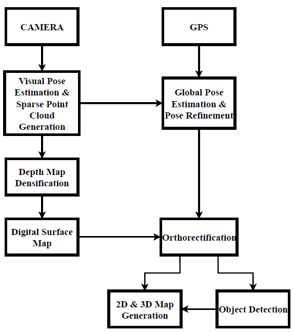
Our Contributions: In this study, we propose a novel real- time mapping and localization pipeline for aerial images built on top of a highly accurate monocular feature-based SLAM method. We fuse GPS and SLAM data for better localization of the UAV and to be able to map the observed environment in multiple UAVs scenario. Although there are methods using SLAM as backbone in mapping methods, we use a fast interpolation method to densify the sparse depth map of feature-based SLAM in order to generate dense 3D maps. While this approach generates semantically strong maps, its main advantage is fast operating time which is crucial for multiple UAVs scenario. In addition, we integrate a state-of-the-art object detection method to the pipeline that allows to acquire real-world positions of the desired objects in the observed environment. Detection of certain objects will be extremely useful for certain applications such as locating lost persons in wilderness or locating some military targets (e.g., vehicles or radar systems) in military operations. Moreover, successful object detection systems return positions of these objects more accurately, therefore these positions can be used as fiducial marker points to align different frames and improve the accuracy of the created 2D/3D maps. To this end, the positions of stationary objects such as buildings, bridges, or military targets such as airports, radomes, and heliports will be extremely useful. An overview of the proposed mapping pipeline is given in Figure 1.
2. Method
In this study, a real-time 2D/3D mapping and object detection pipeline has been developed for both single and multiple UAVs scenarios. The main steps applied for this purpose are analyzed under the following sections: global pose estimation, dense point cloud generation, digital surface map, orthorectification, object detection and orthomosaic.
2.1. Camera Pose Estimation, Sparse Point Cloud Generation and Global Pose Estimation
Digital surface model and orthorectification steps are required to create an orthomosaic with images acquired from a ground-facing monocular camera attached to a UAV. For this purpose, the camera pose estimation and sparse point cloud generation steps are computed by using a feature- based SLAM method in the proposed method. The chosen monocular SLAM method in our work, ORB-SLAM, is a very fast and robust algorithm that can perform in large scale environments. It can compute camera pose accurately due to its robust ORB-based feature tracking, pose graph optimization and loop detection features. However, in monocular SLAM systems, the real world scale cannot be estimated, and the camera pose is given in a local coordinate system. The transformation of the camera pose estimated by the ORB-SLAM to the global coordinate system can be achieved by fusing the GPS data of the UAV and the computed camera pose. In order to calculate the real world scale, the first 20 frames were used for scale estimation at the initialization stage. To this end, the visual and geographic distances between frames are calculated first. Then, the average scale is computed by averaging the scales of the distances between frames which is calculated as,
$$m_{gps} m_{slam} \tag{1}$$
where mgps is the distance between the GPS positions of the two frames, and mslam is the distance between the visual camera pose of the two frames. Once the scale is computed and initialization is done, the camera pose transformation is calculated for the next frames. In order to find the camera pose transformation, a transformation function must be calculated between the two 3D point models of the global positions in UTM (Universal Transverse Mercator) coordinates and the visual poses obtained by ORB-SLAM. Least-squares estimation of transformation parameters between two point patterns [21] is used to calculate the transformation parameters between two 3D point models. After calculating the scale and similarity transformation matrix, the camera pose matrix can be denoted in the global coordinate system as,
$$\begin{bmatrix}
r_{11} & r_{12} & r_{13} & t_E \\
r_{21} & r_{22} & r_{23} & t_N \\
r_{31} & r_{32} & r_{33} & t_A
\end{bmatrix}
\tag{2}$$
where r [ rij ] represents the rotation matrix and t represents the position in UTM coordinate system.
2.2. Dense Point Cloud Generation
Sparse cloud interpolation is used to densify the sparse point cloud of the images after computing global camera pose. First, the depth values of the 3D points calculated by ORB-SLAM are written to the pixel positions in the image plane according to,
$$d\,
\begin{bmatrix}
r_{31} & r_{32} & r_{33} & t_z
\end{bmatrix}
\cdot
\begin{bmatrix}
x & y & z & 1
\end{bmatrix}^{T}
\tag{3}$$
where r3 [r3j] is the last row of the rotation matrix, x, y, z, 1 is the point in the world frame, and z is the height. After re-projecting depth values to the image plane, inpainting is applied to fill the spaces between sampling points. Navier Stokes based Inpainting [22] method is used for inpainting process which is inspired from fluid dynamics. This method travels along the edges of the known regions to the unknown regions as the edges are intended to be continuous. It continues isophotes (lines joining points with the same intensity) and matches gradient vectors at the border of inpainting regions continuously. Empty pixels are filled in a way to reduce the minimum variance in the region. Although the method cannot produce the details of the structures in the observed regions, the output depth maps usually have low noise and homogeneous appearance, and the method works very fast. Sparse point cloud computed by ORB-SLAM must be highly accurate for the method to produce accurate dense depth maps.
2.3. Digital Surface Map
A grid-based method as used in [2] is adapted to create a digital surface map using the generated dense point cloud in the previous stage. GridMap library [23] is used to efficiently handle RGB, elevation, point cloud data with multi-layer grid maps. The library provides rapid manipulation of the image data represented in global coordinates and speeds up the global orthomosaic operation with multi-layer approach. In order to represent the observed surface with a 2.5D grid map containing elevation data, the x and y coordinates of the dense point cloud are structured as a 2-dimensional binary kd-tree [24]. Within a pre-defined interpolation radius (20 pixels radius), the nearest neighbors of the points are calculated. Then, inverse distance weighting is applied to interpolate the map points. Inverse distance weighting intuitively determines the height of the cell using a linear weighted combination of the nearest neighbors. Thus, by giving higher weight to the points closer to the center of the cell, interpolation provides smooth transition and noiseless elevations in the elevation map.
2.4. Orthorectification
After digital surface map generation stage, we have all the data that is required to create the final orthomosaic image. However, the visual distortion caused by the viewing angle and surface structure of the images should be corrected.
Rectification of the images is done by using the camera pose and the digital surface model. Incremental grid-based orthomosaic method [2] is used in orthorectification step. With the corresponding camera pose and the intrinsic matrix of the camera, it is checked whether each cell is in the visible camera cone. The grid map containing the elevation layer of the image is re-sized to the desired ground sampling distance. A 3D point X xi, yi, zi) is created for each cell of the grid. These 3D points are reprojected to the camera image as,
$$x = K\,R\,\bigl[t\,|\,X\bigr] \tag{4}$$
where K is the intrinsic matrix, R|t is the global camera pose matrix. Due to the noisy and erroneous pose estimations on the elevation map, some of the projected points can fall outside of the image boundaries. These points are specified as invalid points and were not back-projected to the image plane.
2.5. Object Detection
The aim of object detection is to classify and localize objects with their labels and bounding boxes in an image. The architectures of generic object detectors can mainly be categorized into two types as regression-based and region proposal based. Region proposal based frameworks first propose regions and then apply regression and classification on these proposals. The other regression-based frameworks skip the region proposal stage and directly predict class probabilities and their bounding boxes using an end-to-end learnable one stream network. In this study, once the rectification stage is completed, object detection can be performed on the RGB data stored in the multi-layer grid map. We use YOLOv3 for object detection in the proposed method. YOLOv3 is an extremely fast regression-based object detection algorithm. YOLOv3 divides images into S × S grids and each grid predicts a fixed number of bounding boxes. YOLOv3 predicts offsets tx, ty, tw, th to the anchor boxes and box confidence score that represents the class probabilities. Instead of directly computing the bounding box coordinates, computing the offsets to the ground-truth box results in a more robust training procedure. YOLOv3 architecture uses a more robust and deeper network called Darknet-53 instead of Darknet-19 [25]. There are residual connections between convolutional layers similar to ResNet [26] structure. YOLOv3 makes predictions at three different scales to improve the performance of detecting small objects in the images which is crucial for aerial images captured in high altitudes. We also used YOLOv3-Tiny architecture which is a faster version of YOLOv3. The local and global coordinates of the detected object can be obtained on rectified images. Then, these positions can be used as fiducial marker points to align consecutive frames and improve the quality of the resulting maps.
2.6. Orthomosaic
All of the data computed in previous stages can be combined to form high resolution 2D and 3D maps. First image taken from the orthorectification stage initializes the global map. After the initialization, the 2D and 3D maps are continuously updated with dense point clouds and orthorectified images using the multi-layer grid map. There are two conditions in the map updating stage. Observed area in the image can be a completely unknown region or the image can overlap with the global map. In the first case, new image data is directly added to the global map and the map is updated. In the second case, the color and elevation values of the intersecting pixels have to be determined in regions where the global map and the image overlap. The color and elevation values of the cells in the overlapping regions are determined by comparing elevation angles between the global map and the image. Cell values in the global map are updated if the elevation angle of the cell is smaller in the new frame. Otherwise, cell values are not updated. The non-maximum suppression is applied to the global bounding box coordinates of the detected objects in consecutive frames to prevent the representation of the same object with more than one bounding box on the global map.

Car Detection: Here, we focus on cars in the mapping area, and train YOLOv3 and YOLOv3-Tiny for car detection in aerial images. To this end, we created our own data set consisting of colored digital images obtained in different weather conditions and scales by using DJI Matrice 600 Pro and DJI Inspire 1 unmanned aerial vehicles. The data set consists of approximately 10.000 colored digital images, and it contains approximately 30.000 aerial view car images. We annotated the cars by using the bounding boxes and created the data belonging to the positive class. Figure 2 shows examples from the data set that contains positive images. We used 80% of the data (approximately 24 K positive samples) for training the YOLOv3 and YOLOv3-Tiny detectors and the remaining 20% of the data is used for testing. NVIDIA Quadro P5000 GPU was used to train the YOLOv3 and YOLOv3-Tiny car models.
To evaluate the performance of the trained detectors, we used PASCAL VOC criterion which is the most commonly used metric for object detection. According to this metric, the position of the object is classified as true or false in accordance with the overlapping ratio of the detected coordinates and the ground truth positions. This overlapping was calculated by using \(\frac{\mathrm{area}\!\left(Q\cap R\right)}{\mathrm{area}\!\left(Q\cup R\right)}\)formula. In this formula, Qshows the ground-truth location of object and R shows the location returned by the algorithm. If this ratio is over 50%, the detected position is considered as true positive TP, otherwise, it is considered as false positive– FP. Then the mean average precision-mAP was determined by using precision-recall curves. Table 1 gives the mAP scores and speeds of the car detectors on the created dataset. The trained YOLOv3 and YOLOv3-Tiny detectors achieved accuracies of 83.4% and 80.2%, respectively in terms of mAP score. In terms of the speed, YOLOv3 and YOLOv3-Tiny methods operate at 22 FPS and 55 FPS respectively, on a laptop with i7 7700HQ processor and NVIDIA GTX1050TI GPU.
Table 1: The mAP scores and speeds of the YOLOv3 and YOLOv3-Tiny detectors on the created dataset.
Method | mAP(%) | Speed (FPS) |
YOLOv3 | 83.4 | 22 |
YOLOv3-Tiny | 80.2 | 55 |
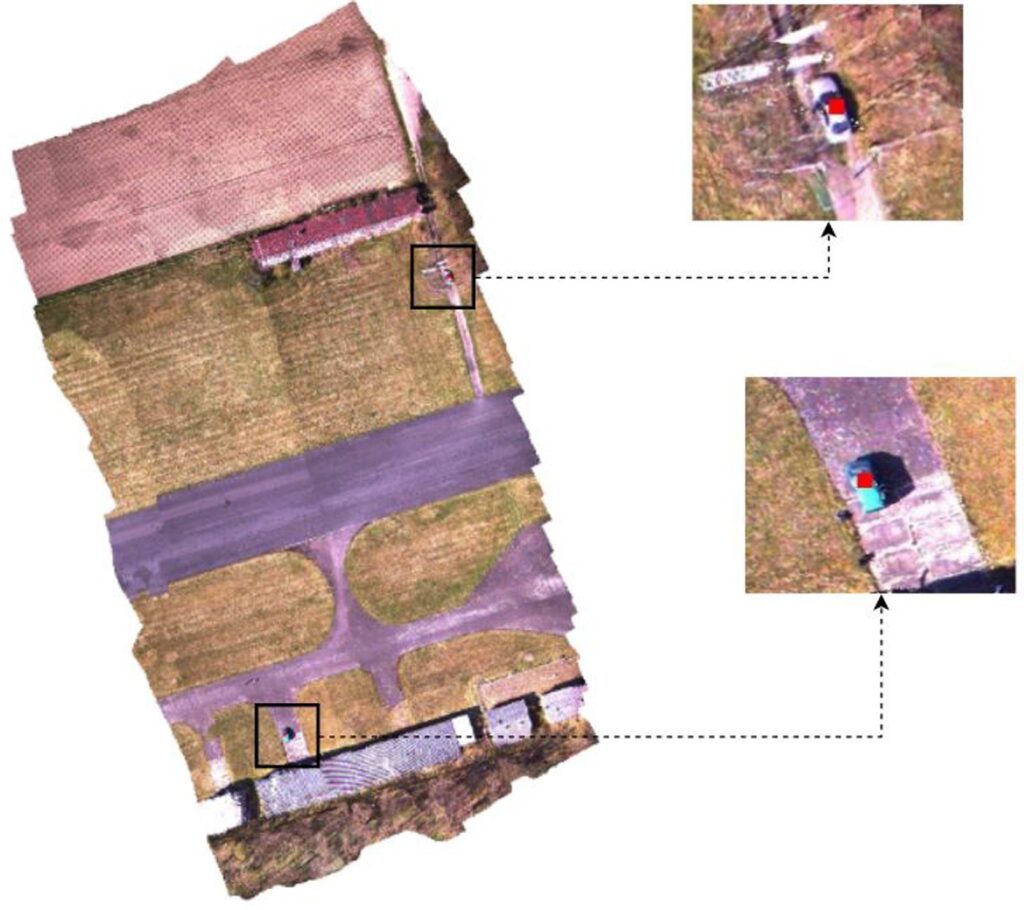
Orthomosaic Generation: For this purpose, aerial images captured with a ground-facing camera attached to a UAV at an altitude of approximately 100 meters were used. Images are captured at 10 FPS with a GoPro Hero3+ camera. The dataset consists of 1500 frames with a size of 1280×720 and the GPS data of each frame is kept in Exif format. Fig. 3 shows the generated orthomosaic and the detected objects in the single UAV scenario. Centers of the detected objects on the map are indicated with red boxes. The orthomosaic given in the figure is generated by using the incremental grid-based orthomosaic approach, selecting the cell values of the image which has the smallest elevation angle in the intersection regions. A good orthomosaic should have high resolution, homogeneous appearance and low geometric distortion. The observed area should be represented as much detailed as possible and aligned correctly in global scale. In the figure, incorrect alignments and seams at the alignment points can be observed due to the incorrect es- timation of the global positions computed by fusing the SLAM and GPS data. However, in the high resolution orthomosaic, structures and the roads can be observed well and cars are localized correctly. The observed environment is reconstructed in a global coordinate system using UTM coordinates. Thus, distances can be measured on a real-world scale, and real-world positions of desired objects can be obtained.
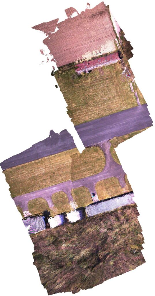
The real world scaling accuracy of the method can be observed better in multiple UAVs scenario. In order to simulate the multiple UAVs scenario, the dataset is divided into two sets and these sets are arranged to have a small intersection between them. The method successfully maps the observed regions to the same plane as shown in Fig. 4 by using the data incoming from different sources.
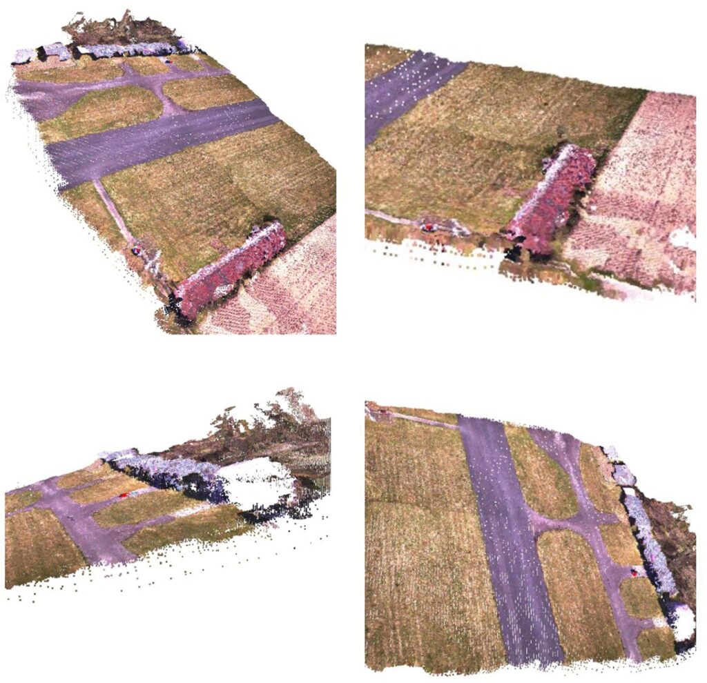
The generated 3D map by using sparse cloud interpolation is given in Fig. 5. Sparse cloud interpolation fails to recover information in sharp elevation transitions. This stems from the fact that the utilized interpolation approach is based on the sparse point cloud computation of ORB SLAM, which uses highly discriminative features for 3D mapping. Consequently, the low resolution of the sparse cloud leads to uncertain elevations, which distorts visual appearance. However, the generated 3D map is homogeneous with low noise and contains sufficient information about the structure of the observed area.
Since there is no ground-truth data to evaluate the performance of the proposed method, ground-truth data is generated with PhotoScan [4] which is a highly accurate offline photogrammetry software. PhotoScan is an advanced computer vision algorithm that robustly estimates camera positions and creates high quality 2D-3D maps. Although it does not perform well in oblique images, it works better than other methods such as Bundler and Photosynth in moving, still, sequential and unordered images. The algorithm consists of three steps. The first step is alignment of the images, estimating camera parameters and positions.
Second step consists of generating dense point clouds and building the geometric scene details on these aligned images. Final step is the texturing of the map with the images. Map and camera positions generated by using Photoscan are considered as ground-truth data.
Table 2: RPE scores of the proposed method, orb-slam and gps on first dataset.
max | mean | median | min | rmse | sse | std | |
ORB-SLAM | 1.12 | 0.27 | 0.25 | 0.02 | 0.35 | 47.32 | 0.22 |
GPS | 2.34 | 0.60 | 0.54 | 0.06 | 0.69 | 194.32 | 0.34 |
OURS | 0.96 | 0.22 | 0.17 | 0.01 | 0.29 | 35.08 | 0.19 |
Table 3: APE scores of the proposed method, orb-slam and gps on first dataset.
max | mean | median | min | rmse | sse | std | |
ORB-SLAM | 2.01 | 0.69 | 0.62 | 0.03 | 0.88 | 222.54 | 0.38 |
GPS | 2.78 | 1.12 | 1.11 | 0.08 | 1.21 | 595.42 | 0.46 |
OURS | 1.75 | 0.52 | 0.46 | 0.01 | 0.63 | 161.15 | 0.35 |
The relative pose error (RPE) and absolute pose error (APE) metrics were used to evaluate the performance of the camera pose estimation [27]. APE, is also called the absolute trajectory error, makes a direct comparison between predictions and reference camera locations. APE tests the global consistency of the trajectory. RPE compares camera movements, motions and calculates translational and rotational drift per meter. We generated trajectories of the proposed method, ORB-SLAM and GPS on the dataset. RPE and APE values of the generated trajectories are compared to the ground-truth data generated by Photoscan in Table 2 and Table 3. The low standard deviation (std) values in the table (below 1 meters for both RPE and APE) indicate that camera pose estimation has low error. In addition, proposed method obtains lower error values than ORB-SLAM and GPS. Which shows that proposed method increases the robustness of ORB-SLAM’s pose estimation.
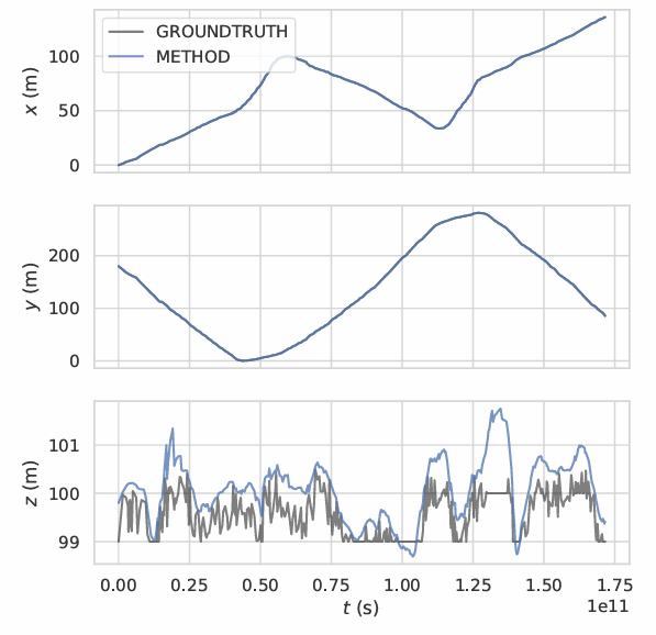
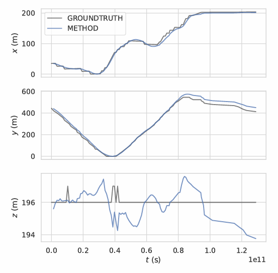
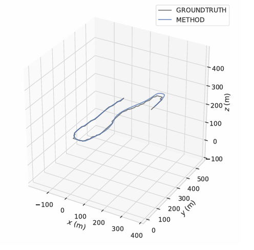
Fig. 6 shows the trajectory graphs according to the plane x, y, z for orthomosaic generated in single UAV scenario. In the x and y planes, the method has not suffered from any shifts or errors. However, when the elevation increases, an instant shift and error occurs in the z plane. The main reason for this situation is ORB-SLAM’s erroneous depth estimation in regions with insufficient features to detect and track. Generated trajectory of the UAV is given in Fig. 7. Robustness and success of the method can also be observed from the figure since trajectory generated with the method is almost equal to ground-truth trajectory. Operation time for the dataset is approximately 4 FPS.
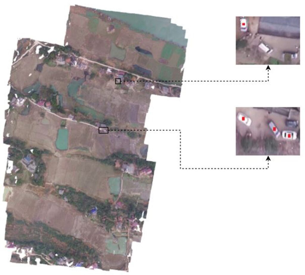
The performance the method is also evaluated in single UAV scenario on phantom3-village dataset introduced in Map2DFusion [12]. Video sequence is recorded at an altitude of approximately 160 meters using DJI Phantom3 equipped with a ground-facing GoPro Hero3+ camera. The dataset consists of 200 frames. Fig. 8 shows the generated orthomosaic and the detected objects on phantom3-village dataset in single UAV case. Generated map achieves satisfactory results on plain regions and areas containing buildings and trees. The method fails to recover information on water regions since generation of the map is highly dependent to the feature-based SLAM approach. This results in some mis-alignments on the generated orthomosaic. Since the altitude is very high, YOLOv3 model failed to detect some of the vehicles.
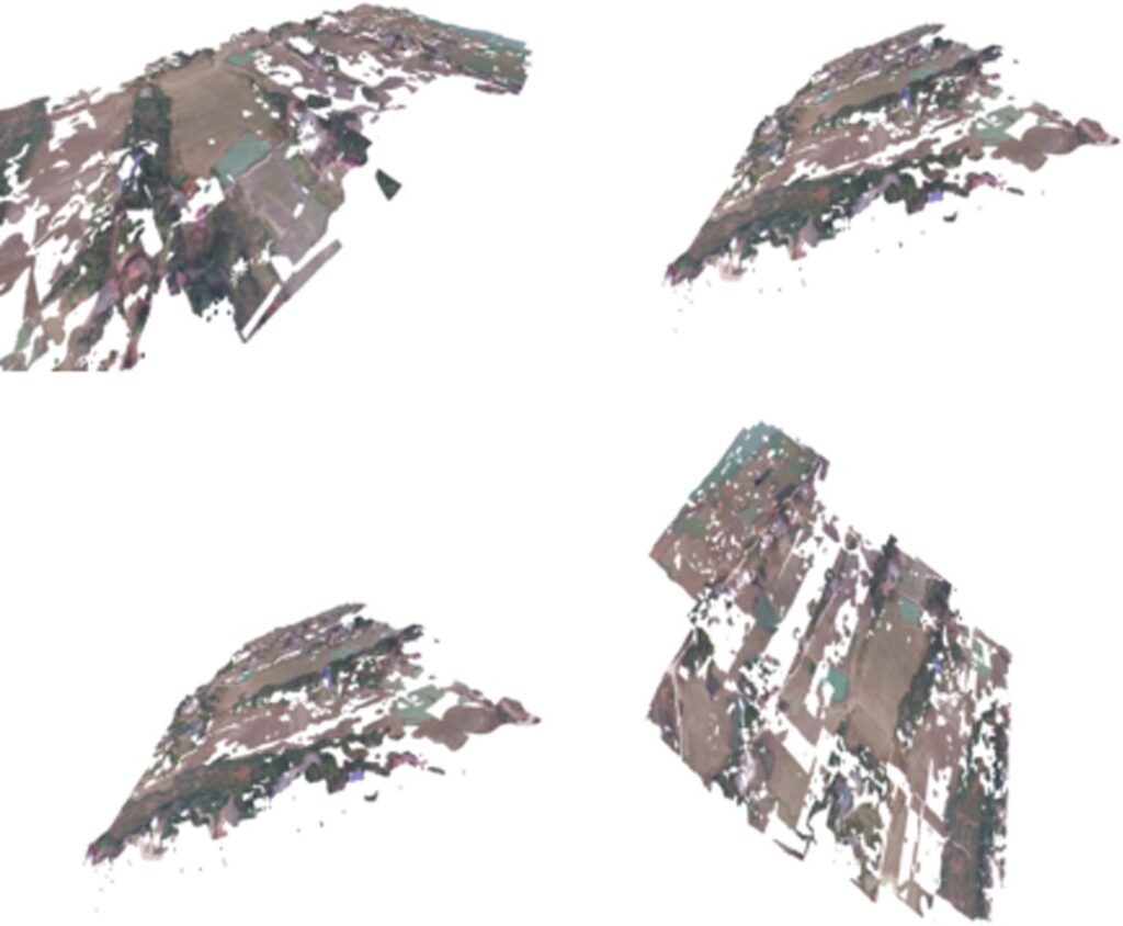
The 3D map generated by using sparse cloud interpolation is given in Fig. 9. Phantom3-village dataset is captured at 1 FPS. Low frame rate severely reduces the ORB-SLAM’s depth map generation performance and this highly affects the depth map interpolation. Pipeline cannot generate 3D surfaces properly on featureless regions due to nature of the feature-based SLAM. Sparse cloud interpolation has difficulties in sharp elevation transitions as in the previous experiment. As seen in the generated 2D map, the method also fails to generate map points for water regions because of the featureless surface of the water.
Since there is no ground-truth data for the dataset, ground-truth data is generated with Photoscan as before. We generated trajectories of the proposed method, ORB- SLAM and GPS on the dataset. RPE and APE values of the methods are compared to the ground-truth data in Table 4 and Table 5. Similar to first dataset, proposed method achieves lowest error for both APE and RPE. The large standard deviation (std) values indicate erroneous camera pose estimations. In the dataset, images captured in high altitudes. This highly affects ORB-SLAM’s pose estimation performance. Fig. 10 shows the trajectory graphs according to the x, y, z plane for orthomosaic generated in single UAV scenario on phantom3-village dataset.
Table 4: RPE scores of the proposed method, orb-slam and gps on phantom3-village dataset.
max | mean | median | min | rmse | sse | std | |
ORB-SLAM | 16.23 | 6.23 | 5.92 | 0.82 | 7.02 | 591.33 | 4.01 |
GPS | 25.95 | 11.23 | 10.68 | 1.32 | 9.42 | 1042.58 | 6.23 |
OURS | 14.68 | 5.63 | 4.81 | 0.73 | 6.49 | 486.70 | 3.21 |
Table 5: APE scores of the proposed method, orb-slam and gps on phantom3-village dataset.
max | mean | median | min | rmse | sse | std | |
ORB-SLAM | 28.12 | 14.02 | 14.75 | 1.28 | 16.12 | 2304.39 | 8.01 |
GPS | 38.17 | 22.19 | 21.34 | 2.26 | 23.12 | 2884.42 | 9.54 |
OURS | 26.11 | 12.69 | 13.63 | 1.07 | 14.34 | 2165.06 | 6.68 |
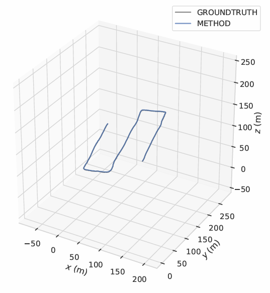
Similar to Fig. 6, the method has not suffered from any shifts or errors in the x and y planes. However, instant shifts and errors can be observed in the z plane. These errors are due to the erroneous depth estimations in featureless regions such as water regions and due to the capturing images at very high altitudes. Generated trajectory of the UAV is given in Fig. 11. Operation time for the dataset is approximately 4.5 FPS.
4. Conclusion
In this study, a real-time 2D and 3D mapping pipeline with object detection ability is developed by combining the camera and GPS data of UAVs. The method uses a robust monocular SLAM method, ORB-SLAM, and point cloud interpolation algorithm, which operates at a very high speed to generate the dense point cloud efficiently. The proposed method creates semantically strong, high-resolution maps and detects objects in real-time using incremental grid-based mosaic and YOLOv3 object detection methods. The proposed method also reconstructs the map in a global coordinate system and obtains the real-world positions of the detected objects. The developed method performs global scaling, object detection, alignment operations efficiently and accurately in both single and multiple UAVs scenarios. The experimental results on two tested datasets show that the mapping pipeline generates a 3D map in real world scale, operates in real time, and the resulting generated map contains semantically strong information about structure of the observed region.
Conflict of Interest The authors declare no conflict of interest.
Acknowledgment This study was funded by the Scientific and Technological Research Council of Turkey (TUBİTAK) under grant number EEEAG-116E080 and Eskisehir Osmangazi University Scientific Research Projects under grant number BAP 202015026.
- Brown, D. G. Lowe, “Automatic panoramic image stitching using invari- ant features”, International Journal of Computer Vision, vol. 74, no. 1, pp. 59–73, 2007.
- T. Hinzmann, L. Scho¨nberger, M. Pollefeys, R. Siegwart, “Mapping on the fly: Real-time 3d dense reconstruction, digital surface map and incremental orthomosaic generation for unmanned aerial vehicles”, “Field and Service Robotics”, pp. 383–396, Springer, 2018.
- Moulon, P. Monasse, R. Perrot, R. Marlet, “Openmvg: Open multiple view geometry”, “International Workshop on Reproducible Research in Pattern Recognition”, pp. 60–74, Springer, 2016.
- Verhoeven, “Taking computer vision aloft–archaeological three- dimensional reconstructions from aerial photographs with photoscan”, Ar- chaeological prospection, vol. 18, no. 1, pp. 67–73, 2011.
- Klein, D. Murray, “Parallel tracking and mapping for small ar workspaces”, “Proceedings of the 2007 6th IEEE and ACM International Symposium on Mixed and Augmented Reality”, pp. 1–10, IEEE Computer Society, 2007.
- Mur-Artal, J. M. M. Montiel, J. D. Tardos, “Orb-slam: a versatile and accurate monocular slam system”, IEEE Transactions on Robotics, vol. 31, no. 5, pp. 1147–1163, 2015.
- Campos, R. Elvira, J. J. G. Rodr´ıguez, J. M. Montiel, J. D. Tardo´s, “Orb-slam3: An accurate open-source library for visual, visual–inertial, and multimap slam”, IEEE Transactions on Robotics, 2021.
- Engel, T. Scho¨ ps, D. Cremers, “Lsd-slam: Large-scale direct monocular slam”, “European Conference on Computer Vision”, pp. 834–849, Springer, 2014.
- Pascoe, W. Maddern, M. Tanner, P. Pinie´s, P. Newman, “Nid-slam: Ro- bust monocular slam using normalised information distance”, “Proceedings of the IEEE Conference on Computer Vision and Pattern Recognition”, pp. 1435–1444, 2017.
- Forster, M. Pizzoli, D. Scaramuzza, “Svo: Fast semi-direct monocular visual odometry”, “2014 IEEE International Conference on Robotics and Automation (ICRA)”, pp. 15–22, IEEE, 2014.
- Pizzoli, C. Forster, D. Scaramuzza, “Remode: Probabilistic, monocular dense reconstruction in real time”, “2014 IEEE International Conference on Robotics and Automation (ICRA)”, pp. 2609–2616, IEEE, 2014.
- Bu, Y. Zhao, G. Wan, Z. Liu, “Map2dfusion: real-time incremental uav image mosaicing based on monocular slam”, “2016 IEEE/RSJ International Conference on Intelligent Robots and Systems (IROS)”, pp. 4564–4571, IEEE, 2016.
- Kern, M. Bobbe, Y. Khedar, U. Bestmann, “Openrealm: Real-time map- ping for unmanned aerial vehicles”, “2020 International Conference on Unmanned Aircraft Systems (ICUAS)”, pp. 902–911, IEEE, 2020.
- Kiss-Ille´s, C. Barrado, E. Salam´ı, “Gps-slam: an augmentation of the orb-slam algorithm”, Sensors, vol. 19, no. 22, p. 4973, 2019.
- Redmon, A. Farhadi, “Yolov3: An incremental improvement”, arXiv preprint arXiv:1804.02767, 2018.
- T.-Y. Lin, P. Goyal, Girshick, K. He, P. Dolla´r, “Focal loss for dense object detection”, “Proceedings of the IEEE International Conference on Computer Vision”, pp. 2980–2988, 2017.
- Liu, D. Anguelov, D. Erhan, C. Szegedy, S. Reed, C.-Y. Fu, A. C. Berg, “Ssd: Single shot multibox detector”, “European conference on computer vision”, pp. 21–37, Springer, 2016.
- Ren, K. He, R. Girshick, J. Sun, “Faster r-cnn: Towards real-time object detection with region proposal networks”, “Advances in Neural Information Processing Systems”, pp. 91–99, 2015.
- Tian, C. Shen, H. Chen, T. He, “Fcos: A simple and strong anchor- free object detector”, IEEE Transactions on Pattern Analysis and Machine Intelligence, 2020.
- Zhu, F. Chen, Z. Shen, M. Savvides, “Soft anchor-point object detection”, “Computer Vision–ECCV 2020: 16th European Conference, Glasgow, UK, August 23–28, 2020, Proceedings, Part IX 16”, pp. 91–107, Springer, 2020.
- Umeyama, “Least-squares estimation of transformation parameters be- tween two point patterns”, IEEE Transactions on Pattern Analysis and Machine Intelligence, , no. 4, pp. 376–380, 1991.
- Bertalmio, A. L. Bertozzi, G. Sapiro, “Navier-stokes, fluid dynamics, and image and video inpainting”, “IEEE Computer Society Conference on Computer Vision and Pattern Recognition (CVPR)”, vol. 1, pp. I–I, IEEE, 2001.
- Fankhauser, M. Hutter, “A universal grid map library: Implementation and use case for rough terrain navigation”, “Robot Operating System (ROS)”, pp. 99–120, Springer, 2016.
- L. Bentley, “Multidimensional binary search trees used for associative searching”, Communications of the ACM, vol. 18, no. 9, pp. 509–517, 1975.
- Redmon, A. Farhadi, “Yolo9000: better, faster, stronger”, “IEEE Society Conference on Computer Vision and Pattern Recognition”, pp. 7263–7271, 2017.
- He, X. Zhang, S. Ren, J. Sun, “Deep residual learning for image recognition”, “IEEE Society Conference on Computer Vision and Pattern Recognition”, pp. 770–778, 2016.
- Kummerle, B. Steder, C. Dornhege, M. Ruhnke, G. Grisetti, C. Stachniss, Kleiner, “On measuring the accuracy of slam algorithms”, Autonomous, no. 4, p. 387, 2009.
No related articles were found.