Geophysical and Geotechnical Investigations for Subsoil Competence at a Proposed Hostel Site at Oba Nla, Akure Southwestern Nigeria

(This article belongs to the Section Geological Engineering (GEE))
Export Citations
Cite
Eebo, F. O. , Samuel, A. B. and Olayanju, G. M. (2022). Geophysical and Geotechnical Investigations for Subsoil Competence at a Proposed Hostel Site at Oba Nla, Akure Southwestern Nigeria. Journal of Engineering Research and Sciences, 1(2), 41–49. https://doi.org/10.55708/js0102005
Festus Olusola Eebo, Abidakun Bayode Samuel and Gbenga Moses Olayanju. "Geophysical and Geotechnical Investigations for Subsoil Competence at a Proposed Hostel Site at Oba Nla, Akure Southwestern Nigeria." Journal of Engineering Research and Sciences 1, no. 2 (March 2022): 41–49. https://doi.org/10.55708/js0102005
F.O. Eebo, A.B. Samuel and G.M. Olayanju, "Geophysical and Geotechnical Investigations for Subsoil Competence at a Proposed Hostel Site at Oba Nla, Akure Southwestern Nigeria," Journal of Engineering Research and Sciences, vol. 1, no. 2, pp. 41–49, Mar. 2022, doi: 10.55708/js0102005.
A foundation study was carried out at a proposed Hostel site for the student of Federal University of Technology Akure, Nigeria with the aim of evaluating the competence of the overburden as foundation materials. Geophysical survey involving Electromagnetic method and magnetic method were conducted in conjunction with geotechnical tests in the study area. Electromagnetics and Magnetics data were acquired along the five traverses established across the study area with 20 m inter-traverse spacing and 5 m inter-station spacing. The geophysical results were interpreted qualitatively and quantitatively, and the results were presented as profiles and geomagnetic sections. From the results of the Very Low Electromagnetic survey conducted, several conductive zones possibly characterized by clayey materials were found to make up the overburden materials in the area. Characteristic magnetic anomalies in the area also revealed series of features at shallow depths identified to be fractures / fault at shallow depths with depth to bedrock varying between 2 m and 7 m. The presence of geologic features such as fracture and conductive clayey materials are likely going to pose a serious threat to engineering structure in the area. Geotechnical tests were carried out on soil samples from the study area and different geotechnical parameters analyzed include the natural moisture content, Atterberg Limits, unconfined compressive strength and shear strength. The specific gravity of the soils is within the range of 2.722 – 2.73 g/cm3, revealing materials of low water absorption capacity. However, the soils are highly plastic with the plastic limit ranging from 20.4 – 24.4% and a plasticity index range of 23.75 – 35.90%. In addition, the soils have shear strength within the range of 75 to 102 kPa and unconfined strength ranging from 150 to 203 kPa revealing stiff soils that are not suitable for shallow foundations. It was observed that the form of foundation suitable for infrastructural development in the study area is a properly designed deep foundation that can transfer load at grater depths.
1. Introduction
Incessant failure of structures such as road, buildings, dam and bridges has become a common phenomenon in many parts of Nigeria. Hence, there is a need to identify the cause(s) of structure failure and find a means of tackling the problem to prevent loss of valuable lives and properties. Factors that can be responsible for structural failures include bad design, faulty construction, foundation failure and over loads.
A reliable foundation design depends on the characteristics of both the geological structures and the near subsurface soil or rock. Therefore, the nature (i.e. competence, strength and load bearing capacity) of the soil supporting the super structure becomes an extremely important issue of safety, structural integrity and durability of the super structure. Hence, a detail investigation of the subsoil is required by non-destructive techniques such as geophysical methods which respond to the heterogeneous nature of soil particles through some physical parameters that govern the subsoil competency [1].
Foundation study usually provides subsurface information that normally assists civil engineers in the design of foundations. Standard engineering practice requires investigation of soil and the subsurface at the site chosen for engineering construction. This is routinely done to ascertain the sustainability of the earth material at such site for proposed structures i.e., in terms of bearing capacity and/or host fitness. Despite, some of the pre-construction investigation by site engineers, some impacts of infrastructural failures can manifest as ground subsidence, major cracks, failed road segment and fractional settlement of the structures [2] – [4]. These factors can be attributed to geologic nature of the environment where the structures are emplaced. Integrated geophysical and geotechnical investigations for foundation design have proved to be good veritable tools in effective foundation design and construction [5], and these methods are much more suitable in providing information about geologic and geophysical parameters that can aid foundation studies at low cost and time effective.
Environmental geophysics provides a wide range of geophysical methods that can effectively provide spatial information about the homogeneity of subsurface materials as well as structural disposition of the areas demarcated for civil engineering constructions in terms of suitability, integrity and load capacity of construction materials at low costs and man power size [6], [7].
On like sedimentary area where pronounced geological factor could be attributed to lithification and settlements of sedimentary overburden, geological factors in crystalline environment three major causes of potential failures of infrastructures are failure due to lateral inhomogeneity of the subsurface layers, failure precipitated by differential settlement and failure initiated by fractures and faults [8]-[10]. Therefore, since there is no substitute for pre-foundation investigation of proposed site for engineering structure in order to ensure effective construction programme.
In this paper, integrated geophysical and geotechnical evaluation of subsoil competence and suitability for erecting proposed hostel at site within the FUTA campus is presented. The investigation carried out focused on the suitability of the study area for civil engineering structures by mapping the subsurface conductive zones and geologic structures in order to identify subsurface structures or features that could be inimical to foundation in the area. The knowledge of spatial presentation of these structurally weak subsurface futures and zones are of great advantage for ensuring good foundation of infrastructures in the study area.
2. Study Area
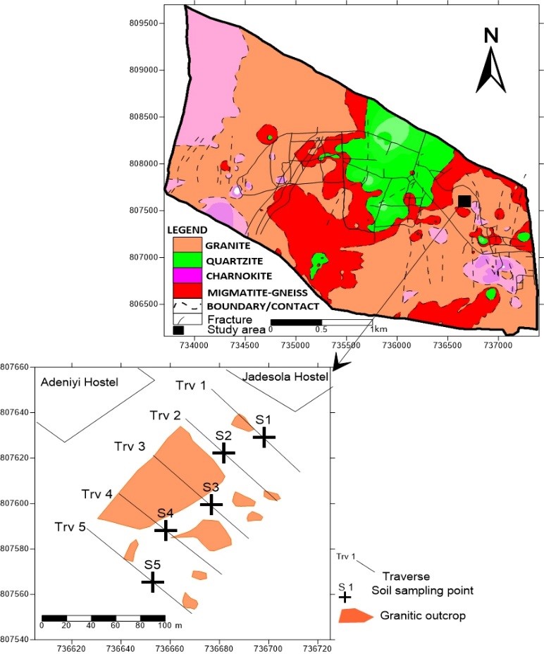
The study area is located inside the Federal University of Technology, akure (FUTA). It is accessible through FUTA north gate via the road to the undergraduate hostel directly opposite jadesola and Adeniyi hostels and from South gate via the futa piggery section (Figure 1). The study area is bounded by Easting 736677E to 736669E and Northing 807650N to 807614N in Universal Traverse Mercator (UTM) coordinate system and Minna Zone 31 datum [11].
The study area is underlain by rocks of Precambrian Basement Complex of Southwestern Nigeria [12]. The crystalline rocks are porphyritic granite, biotite granite, quartzite and gneiss migmatite, while Charnokites rocks occur as discrete bodies in other parts of the area (Figure 1). The geology and boundaries of the lithological units were inferred in places where they are concealed by superficial residual soil.
3. Methodology
3.1. Geophysical Survey
3.1.1. VLF-EM Survey
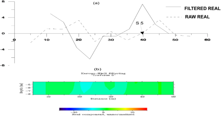
Five traverses were established across the study area for both the VLF and magnetics surveys conducted. The VLF receiver used for the EM survey is a hand-held receiver measuring the tilt-angle of the magnetic field polarization ellipse. The tilt-angle is obtained by rotating the instrument until a null is obtained (indicated audibly through a speaker, if the instrument is audio enabled) then, the angle is read from an inclinometer mounted on the instrument case. Field traverses were located perpendicular to strike direction so the anomalous zones can be compared to background levels. VLF data were collected along traverses, and anomalies are correlated from traverse to traverse. The sampling interval of 5m was used for the EM survey and the mode of measurement adopted was point-by-point data measurement with traverse-traverse spacing of 20 m. The VLF data was filtered using the Karous-Hjelt filter to enhance the data and convert the tilt-angle crossovers into peaks. The “real” and “imaginary” components of data collected from the field were plotted against distance along the traverse. The VLF data was interpreted qualitatively by the visual inspection of profiles generated from the data for anomaly signatures.
3.1.2. Magnetic Survey
The magnetic measurements were recorded using a proton precision magnetometer that involves the total magnetic intensities. Measurement of ground magnetic intensities were made along the five established traverses with station-to-station separation of 5m and traverse to traverse spacing of 20m. The ground magnetic survey conducted in the study area was processed to prepare the dataset for interpretations. The data processing steps includes, removal of International Geomagnetic Reference Field (IGRF) from the magnetic reading at each station, application of moving average filter to remove high frequency noise, removal of main magnetic field using polynomial fitting along the traverses. The residual is the obtained by removing the regional field calculated, where the expression for the residual anomaly becomes;
$$F_R = F_T – F_M \tag{1}$$
where FM is the residual anomaly, FT is the measured total field and FR is the computed main field plus regional anomaly. The residual magnetic field is then presented as magnetic profiles and the depth estimation of the basement in the area was carried out using half-slope method and straight slope method [7].
3.2. Geotechnical Tests
3.2.1. Sample Collection
Five undisturbed soil samples were collected at different locations at a depth of 1m within the site.
These samples were preserved in a labelled polythene bags and transported to the laboratory.
The natural moisture content of the samples collected from the field was determined in the laboratory within a period of 24 hours after collection. This was followed by air drying of the samples by spreading them out on trays in a fairly warm room for four days. Large soil particles (clods) in the samples were broken with a wooden mallet. Care was taken not to crush the individual particles. The geotechnical tests conducted on the samples include the Natural Moisture Content determination, Atterberg Limits test, Compaction test, Shear Strength test and Unconfined Compressive Test. Methods of testing soils for engineering parameters were conducted in accordance with [13] for all the soil samples collected.
3.2.2. Atterberg limits test
Atterberg limits test was carried out on five soil samples taken randomly in the study area at a depth of 1 m. For the soil samples collected, a soil mass of at least 200 g which has been sieved through a 425 micron sieve was used. The geotechnical parameters derived from the Atterberg Limits Test include the Plastic limit, the Liquid limit and the linear shrinkage.
The liquid limit describes the moisture content at which the soil is on the verge of becoming a viscous fluid. The plastic limit is the water content where soil starts to exhibit plastic behaviour. It is a measure of the water content at which the soil begins to crumble when rolled into a thin thread of about 3 mm in diameter.
The linear shrinkage is described as the water content of a soil at which any further reduction in the water content does not result in a change of volume of that soil.
The linear shrinkage is given by the expression
$$LS=\frac{L_i-L_f}{L_i}\times 100 \tag{2}$$
where Li = length of the specimen before drying;
Lf = length of specimen after drying.
3.2.3. Compaction Test
Compaction test was carried out for the various soil samples collected using the AST 698 standard proctor. 10 lbs of each samples analysed sieved through sieve No. 4 are placed in a mould of 944 cm3 volume without the base and the collar. The compaction apparatus was assembled and the soil sample placed in the mould in 3 layers and compacted using 25 well distributed blows of the proctor hammer per layer with the collar and base in place. The collar was detached without disturbing the soil inside the mould. The base is removed the weight of the mould and compacted soil recorded. The compacted soil is the removed from the mould, the moisture content of 20-30 g of the sample determined. The remaining sample is then placed in the pan, broken down, and thoroughly remixed in 100 g of water and procedure repeated to obtain a set of 5 records of the average moisture content and dry density of the samples. Compaction curves are then drawn from the results in order to determine at which point on the compaction the specific amount of water will produce the maximum dry density, which is known as the optimum moisture content.
3.2.4. Unconfined Compression (UC) Test
The Unconfined compressive strength of the soil in the area defines the compressive strength at which an unconfined cylindrical specimen of a soil will fail in a simple compression test. In this test, the unconfined compressive strength is taken as the maximum load attained per unit area, or the load per unit area at 15% axial strain. Soil samples were compacted into a hollow cylindrical cutter to achieve maximum density, from which trimmed sample in a cylindrical shape with height to diameter ratio of 2:1 was weighed using a balance. The soil mass was then tested for unconfined compressive strength in the UCS machine by applying load at a constant rate until the soil failed. The dial reading was recorded with load increase, while the load at which failure occurs represents the peak of compressive stress for the sample, which is the soil compressive strength. The trimmed cylindrical soil samples were thereafter tested for untrained shear strength in the triaxial test apparatus in accordance with [14]
4. Results and Discussions
4.1. Geophysical Survey
4.1.1. Very Low Frequency Electromagnetic (VLF) Survey.
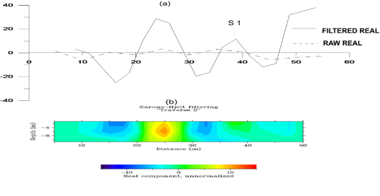
On the filtered real component of the VLF-EM survey profile, positive peaks are indication of high conductive zones, which could be probable fault, fracture, or clay materials deposit. These conductive zones are detrimental to engineering foundation construction. Several positive peaks were observed on the filtered real profiles along the 5 traverses (Figures 2-6), which suggest conductive zones characteristic of clayey material, fractures, or some other linear features. From traverse 1, a conductive body was delineated within 10-15m and a highly conductive body was obtained within 30-35m along the same traverse (Figure 2).
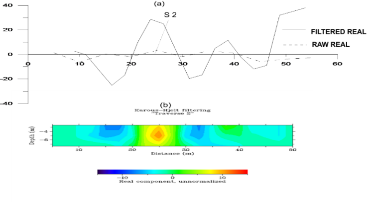
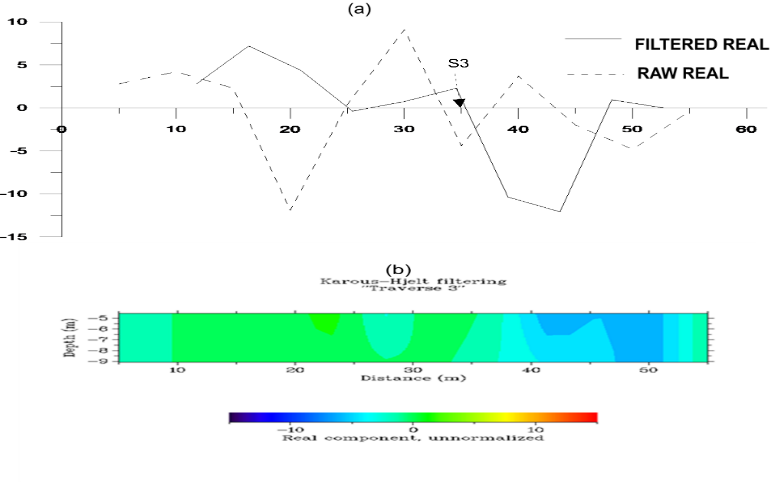
In Figure 3, a low conductive body at 22-28 m and 36-40 m were delineated from the current density section. The highly and negative zone between 22 m and 28 m appears to be a boulder while the other conductive body have a characteristic of a clayey material at shallow depth. In Figure 4, an extensive conductive zone was observed to the west from the beginning of the traverse to a distance of 38 m, while a resistive body recognized to be a migmatite gneiss intrusion lies between 40m and 52 m. Similarly, from Figure 5, a high conductive body was delineated from 22-33 m along the traverse. The conductive body appears to be an extension across the traverse. The VLF-EM current density shown in Figure 6 indicates the presence of conductive bodies along the traverse. It was observed that the overburden material is generally conductive along this traverse.

4.1.2. Magnetic Profiles
A total of five traverses were occupied and the results of the interpreted magnetic fields (residual anomalies) displayed as residual anomaly profiles were used in the generation of geo-magnetic sections (Figure 7-11)
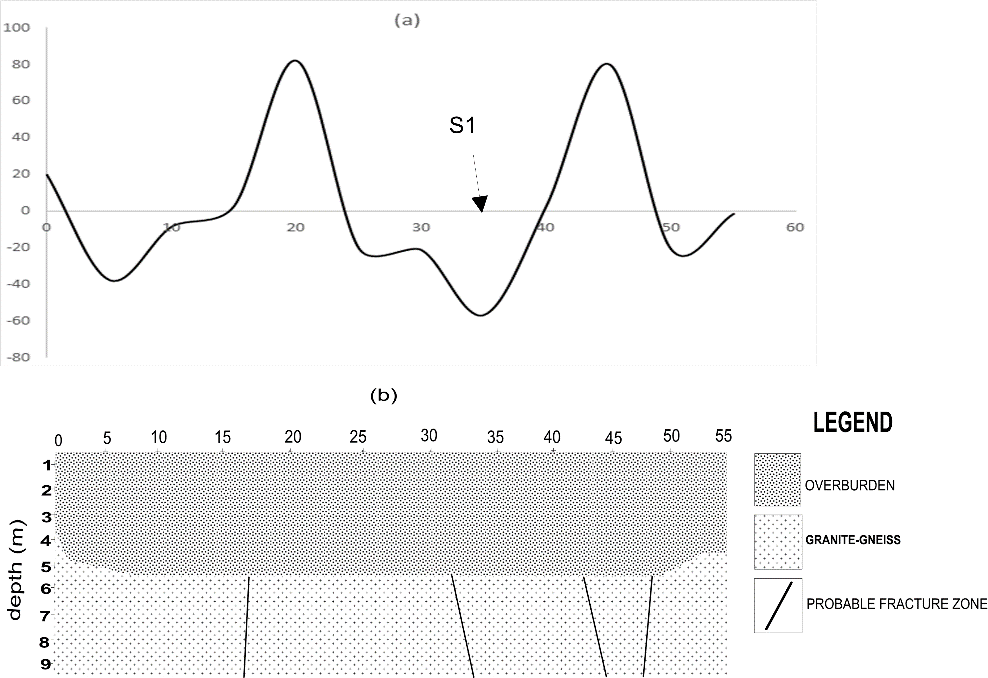
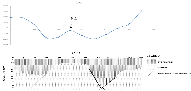
The residual magnetic profile along traverse 1 is shown in Figure 7a with anomaly amplitude varying between -60 nT and 80 nT. The varying magnetic intensity suggests varying magnetic materials associated with the rock types in the area. The high amplitude at a distance between 20 m and 40 m suggest the presence of an intrusive body in the form of a dyke within the basement rock occurring at a shallow depth below the surface. The current density section shown in Figure 2b revealed an intruding resistive body at this point of anomaly, the depth to top of the anomaly was estimated to be 3 m and 6 m. The magnetic profile for traverse 2 is shown in Figure 8a. The profile shows amplitude variation between -191nT and 308 nT. A projecting anomaly observed between a distance of 18 m and 30 m appears to be characteristic of a dyke, which was observed to be a conductive body at shallow depth in the EM-VLF current density section in Figure 3b. The magnetic profile and geomagnetic section for traverse 3 are presented in Figure 9. The profile shows amplitude variation between -225 nT and 488 nT. The varying magnetic intensity suggests varying magnetic materials associated with the rock types in the area. The positive anomaly observed between the distances of 38-55 m suggests a change in rock types from granite to migmatite gneiss. The preluding anomaly between 12 m and 20 m is observed to be an extension of anomaly recognized along traverse 1 and 2 as an intruding dyke-like structure, which correspond to the conductive body observed in the current density sections in Figure 2b and 3b. The magnetic profile and geomagnetic section for traverse 4 are presented in Figure 10, where the profile shows amplitude variation between -1200 nT and 900 nT.
The varying magnetic intensity suggests varying magnetic materials associated with the rock types of different lithology and mineral content. The magnetic signature changing from high negative to positive anomaly at a distance from 40 – 55 m is characteristic of boundary between the granite and migmatite gneiss. The geomagnetic section reveals that the overburden thickness ranges from 3 m and 7 m along the traverse. The magnetic profile and geomagnetic section for traverse 5 are presented in Figure 11. The anomaly amplitude varies between -2100nT and 1400nT at a distance of 30 – 40 m suggesting varying magnetic intensity associated with varying magnetic materials in the underlying rock type in the area. The observed anomaly signature corresponds to contact between two rock types. Depth to bedrock ranges from 2m and 7m along the traverse.


4.2. Geotechnical Analyses
The results from the various geotechnical analyses conducted on the soils samples from the study area are shown in Tables 1 and 2. From Table 1, the soil sample from the study area have a plastic limit range of 20.4 – 24.4% and a plasticity index range of 23.75 – 35.90% indicating a soil of high plasticity in according with [15]. Thus, the soils at the study location are not suitable for shallow foundations.
4.2.1. Particle Size Distribution and Specific Gravity
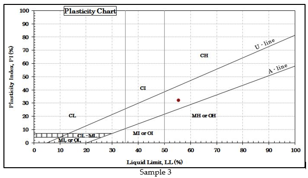
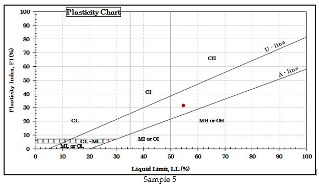
From Table 2, the percentage of silt and clay in the soil sample from the study area is within the range of 45.8 – 73.8% indicating that the soil samples are silty clay, which is not suitable for shallow foundation construction. The specific gravity values of the soil samples are within the range of 2.722 – 2.73 g/cm3, which allows the rating of soil samples as good foundation material due to their low water absorption capacity. From Figure 12-16, the soil samples are above the A-line on the plasticity chart indicating that they are very plastic, thus making them unsuitable for foundation construction because they can crack when dry.
Table 1: Summary of Atterberg limits test, UC test, Compaction Test of Soil sample from the study area
Sample No | 1 | 2 | 3 | 4 | 5 |
Liquid limit (%) | 56.30 | 46.10 | 55.50 | 56.40 | 54.70 |
Plastic limit (%) | 20.40 | 22.40 | 23.50 | 24.40 | 23.40 |
Shrinkage limit | 7.70 | 8.70 | 7.70 | 7.70 | 7.70 |
Linear shrinkage | 11.40 | 10.00 | 11.40 | 11.40 | 11.40 |
Field Moisture content (%) | 16.20 | 14.60 | 17.10 | 17.20 | 16.80 |
Swell index | 0.29 | 0.32 | 0.31 | 0.30 | 0.31 |
Plasticity index | 35.90 | 23.75 | 32.05 | 32.00 | 31.30 |
Flow index | 6.59 | 6.59 | 6.59 | 6.59 | 6.59 |
Consistency index | 1.12 | 1.33 (Very stiff) | 1.20 (Very stiff) | 1.23 (very stiff) | 1.21 (very stiff) |
Liquidity index | -0.12 | -0.33 | -0.200 | -0.23 | -0.21 |
Average specific gravity | 2.723 | 2.722 | 2.727 | 2.722 | 2.731 |
Unconfined compressive strength (kPa) | 203.2 | 150.3 | 165.5 | 159.9 | 172.6 |
OMC (%) | 27.6 | 25.7 | 27.8 | 27.9 | 27.1 |
Shear strength (kPa) | 101.58 | 75.16 | 82.73 | 79.97 | 86.29 |
MDD (kg/m3) | 1528 | 1593 | 1521 | 1518 | 1545 |
BSCS Group Symbol | CH | CL | CH | CH | CH |
Note: CH= High plasticity silty clay or clayey soil, CL= low plasticity silty clay.
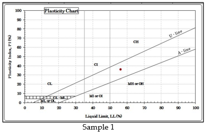
Table 2: Summary of Particle Size Distribution of Soil Samples from the Study Area
Sample number | 1 | 2 | 3 | 4 | 5 |
Gravel (%) | 1.4 | 0.0 | 0.0 | 0.0 | 0.0 |
Sand (%) | 52.9 | 27.3 | 27.5 | 26.1 | 27.3 |
Silt (%) | 13.5 | 34.6 | 34.7 | 36.4 | 33.5 |
Clay (%) | 32.3 | 38.1 | 37.8 | 37.4 | 39.2 |
Moisture content (%) | 16.2 | 14.6 | 17.1 | 17.2 | 16.8 |
Average specific gravity | 2.723 | 2.722 | 2.727 | 2.722 | 2.731 |


4.2.2. Compaction Test
The compaction test was conducted to determine the maximum dry density (MDD) value of a soil sample with respect to its load capacity. The maximum dry density and optimum moisture content were determined from the results of the test using the [3] guidelines for compaction tests to determine their compaction parameters from the plot of the dry density against the moisture content. From Table 1, the OMC values are within the range of 25.7 – 27.9 % and the MDD values within the range of 1518 – 1593 kg/m3.
4.2.3. Unconfined Compression Test
From Table1, the soil samples have shear strength value within the range of 75.16 – 101.58 kPa and unconfined compressive strength range of 150.3 – 203.2 kPa indicating that the soil samples are very stiff according to [16]. A very stiff soil is not suitable for foundation construction due to the fact that it can easily become plastic when wet.
5. Conclusions
The results of integrated geophysical and geotechnical evaluation of a site for development of proposed infrastructures for students’ residential purpose have been presented to address suitability of soil material to sustain building and other civil constructions. From the geophysical surveys, several conductive zones identified to be characterized by clayey materials were observed to make up the overburden materials from the results of the EM-VLF survey conducted, while characteristic magnetic anomalies in the area also revealed series of features at shallow depths identified to be fractures / fault at shallow depths. Implications of these structural features suggest that, the overburden is generally prone to future instability from shear movement of erected structures, weakness of the overburden due to clayey nature of overburden in some areas and possible percolation of surface water into the foundations if proper stabilization and reinforcements are not made to enhance the load capacity of soil in the area as foundation material. However, places with shallow competent bedrock devoid of inimical features such as fractures or clayey overburden materials are appropriate for infrastructural development in the stud area.
From the geotechnical investigation, the soil samples were found to be characterized by high plasticity and poorly graded soil with high clay content. The result of compaction test revealed that the soils have shear strength within the range of 75 to 102 kPa and unconfined strength ranging from 150 to 203 kPa suggesting stiff soils which are not suitable for shallow foundations.
Thus, the combined application of geophysical and geotechnical methods in evaluating the soil stability and capacity for carrying effective loads for the infrastructural development of the area has shown that a comprehensive design of suitable foundation programme must be embarked for the construction of the proposed students’ hostel and other facilities in the area. Presence of fractures/ faults at shallow depth may results in development of cracks and lateral displacement of some parts of the structure if proper preventive measure were not taken at construction stage. It is therefore concluded that a deep foundation will be more appropriate to transfer load at grater depths due to the weakness of the overburden materials to accommodate and transfer loads.
6. Recommendations
In this paper the significance of geophysical and geotechnical investigations as part of pre-foundation evaluation has been demonstrated for the design foundations. In this particular case, it is recommended that for proper designing of the foundations of the proposed structures in the study area, the foundation pavements must be founded on competent underlying bedrock, which is close to the surface in the area since the near surface lithology revealed occurrence of highly plastic and clayey materials. In addition, preventive measures must be taken to avoid lateral movement that can result in the shearing of parts of the proposed structures.
Conflict of Interest
The authors declare no conflict of interest.
The research was self-funded by the authors.
Acknowledgement
The authors sincerely appreciate the assistance of the Mr. Mamukuyomi, A. who was involved in the geophysical data collection and the technical staff of Applied Geology Department, FUTA that also assisted in geotechnical tests conducted.
- S. Bayode, A. A. Egbebi, “Subsoil Characterization for Foundation Stability Using Geophysical and Geotechnical Methods,” Journal of Environment and Earth Science. Vol.10, No.6, 2020.Pp. 8, 2020, https://doi.org/10.7176/jees/10-6-08
- L.O. Ademilua, M.O. Olorunfemi, “A geoelectric/ geologic estimation of groundwater potential of the basement complex area of Ekiti and Ondo state, Nigeria,” Journal of Technoscience Vol. 4, Pp 4-18, 2000, https://ouci.dntb.gov.ua/en/works/legBpwg7/
- M.O. Olorunfemi, A.I. Idornigie, A.T. Coker, G.E. Babadiya, “On the application of the electrical resistivity method on foundation failure investigation- a case study,” Global Journal of Geological Sciences, Vol 2(1), Pp139-151, 2004, https://doi.org/10.4314/gjgs.v2i1.18689
- O.J. Akintorinwa, F.A. Adelusi, “Integration of geophysical and geotechnical Investigations for a Proposed Lecture Room Complex at the Federal University, Akure, Nigeria,” Journal of Applied Sciencs Vol 2(3): Pp 241, 2009, https://www.scirp.org/%28S%28vtj3fa45qm1ean45vvffcz55%29%29/reference/referencespapers.aspx?referenceid=2674470
- O. O. Falowo, M. B. Amodu, “Engineering Subsoil Characterization for Shallow Foundation Design in Ode Irele Area of Ondo State, Southwestern Nigeria,” European Journal of Environment and Earth Sciences. Vol 1 (2), 2020, http://dx.doi.org/10.24018/ejgeo.2020.1.2.6.Pg.1
- W.M.Telford, L.P. Geldart, R.G.Sheriff, D.A. Keys, “Applied Geophysics Published by Cambridge University Press, Cambridge,” pp7 – 215, 632 – 692, 1976, https://www.scirp.org/(S(i43dyn45teexjx455qlt3d2q))/reference/ReferencesPapers.aspx?ReferenceID=1748399
- J. M. Reynolds, (1997): “An introduction to Environmental Geophysics, John Willey & Sons London,” U.K. 796pp, https://scirp.org/reference/ReferencesPapers.aspx?ReferenceID=1236461
- M.O. Olorunfemi, J.O. Fatoba, L.O. Ademilua, “Integrated VLF-Electromagnetic and Electrical resitivity survey for groundwater in a crystalline basement complex terrain of southwestern Nigeria,” Global Journal of Geological Sciences, Vol.3, No. 1, Pp 71-80, 2005, DOI: 10.4314/gjgs.v3i1.18714
- M.O. Ofomola, K.A.N. Adiat, G.M. Olayanju, B.D. Ako, “Integrated geophysical methods for post foundation studies, Obanla staff Quarters of the Federal University of Technology Akure, Nigeria,” Pacific Journal of Science and Technology, Vol 10(2), Pp 93-111, 2009, https://citeseerx.ist.psu.edu/viewdoc/download?doi=10.1.1.500.1327&rep=rep1&type=pdf
- A.O. Adelusi, A.A. Akinlalu, A.I. Nwachukwu, “Integrated geophysical investigation for post-construction studies of buildings around School of Science area, Federal University of Technology, Akure, Southwestern, Nigeria,” International Journal of Physical Science, Vol 8(15), Pp 657-669, 2013, https://doi.org/10.5897/ijps2012.0204
- G.M. Olayanju and A.O.Ojo, “Magnetic Characterisation of Rocks Underlying FUTA Campus, South-Western Nigeria,” Journal of Environment and Earth Science, Vol. 5, No. 14, pp 113 – 127, 2015, https://www.iiste.org/Journals/index.php/JEES/article/view/24260 .
- M.A. Rahaman, “Review of the basement geology of southwestern Nigeria in Geology of Nigeria,” Elizabethan Publishing Company, Nigeria. Pp. 44 – 58, 1976, http://www.sciepub.com/reference/51956
- American Society for Testing Materials, ASTM, 1557, “Test Method for Laboratory Compaction Characteristics of Soil Using Modified Effort,” Annual Book of ASTM Standards, 1991, https://shop.iccsafe.org/astm-d-1557-07-test-method-for-laboratory-compaction-characteristics-of-soil-using-modified-effort-56-000-ft-lb-ft3-2-700-kn-m-m3-pdf-download.html
- British Standards Institution, BS 1377, “Methods of Test for Soils for Civil Engineering Purposes,” British Standards Institute, Milton Keynes, 1990, http://worldcat.org/isbn/058018030
- American Society for Testing Materials, ASTM, “Standard test method for classification of soils for engineering purposes (Unified Soil Classification System),” ASTM standard D2487-90, 1992. Annual Books of ASTM Standards, Vol. 04.08, sec. 4, 1992, https://lauwtjunnji.weebly.com/uploads/1/0/1/7/10171621/astm_d-2487_classification_of_soils_for_engineering_purposes_unified_soil_classification_system.pdf
- R.B. Peck, W.E. Hanson, T.H. Thornburn, “Foundation Engineering, 2nd Edition,” Willey, New York, Pp 113-115, 1974, https://www.worldcat.org/title/foundation-engineering-by-rb-peck-walter-e-hanson-thomas-h-thornburn/oclc/503644451