Physical Interpretation of the Solution to the Problem of Diffraction on a Half-plane with Non-Ideal Boundary Conditions
(This article belongs to the Special Issue on SP1 (Special Issue on Multidisciplinary Sciences and Advanced Technology 2022) and the Section Applied Mathematics (APM))
Export Citations
Cite
Vesnik, M. (2022). Physical Interpretation of the Solution to the Problem of Diffraction on a Half-plane with Non-Ideal Boundary Conditions. Journal of Engineering Research and Sciences, 1(3), 52–58. https://doi.org/10.55708/js0103006
Michael Vesnik. "Physical Interpretation of the Solution to the Problem of Diffraction on a Half-plane with Non-Ideal Boundary Conditions." Journal of Engineering Research and Sciences 1, no. 3 (March 2022): 52–58. https://doi.org/10.55708/js0103006
M. Vesnik, "Physical Interpretation of the Solution to the Problem of Diffraction on a Half-plane with Non-Ideal Boundary Conditions," Journal of Engineering Research and Sciences, vol. 1, no. 3, pp. 52–58, Mar. 2022, doi: 10.55708/js0103006.
The recently proposed method of fundamental components is employed to develop a technique for obtaining a heuristic solution to the problem of diffraction on a half-plane with non-ideal boundary conditions. The difference between the new method and traditional heuristic approaches, such as the geometric theory of diffraction and the method of edge waves, is the presence of an adjustment procedure which allows increasing the accuracy while maintaining the compactness of the formulas. For the case of the problem of diffraction on an impedance half-plane, heuristic formulas are constructed. Then they are refined using a verification solution. A quantification of accuracy is carried out, and a physical interpretation of the solution is presented. The prospects for applying this approach to constructing high-speed solvers and carrying out the physical interpretation of numerical solutions are discussed.
1. Introduction
Topical practical problems, such as the study of scattering on targets with low radar visibility, the propagation of electromagnetic waves in urban areas, etc., require the use of special solvers. These solvers, in turn, require efficient (i.e., fast and accurate) methods for solving diffraction problems [1].
In the topical problems mentioned above, which can be classified as diffraction by polygons and polyhedra, there are many edges with various shapes and boundary conditions. Computer resources may not be enough to apply numerical methods, and it is unlikely to obtain rigorous analytical solutions for all of them. One has to apply heuristic formulas [2 – 5]. The recently developed Method of Fundamental Components (MFC) [6 – 8] offers an efficient solution to this problem. Heuristic formulas obtained employing MFC are compact, fast, and, unlike known heuristic approaches, accurate in an entire range of parameters [8].
The MFC heuristic solution is based on a set of fundamental components [8]. At the first stage it is the solution of the simplest problems of diffraction. Furter, these solutions are refined using other basic components and a verification solution (usually, numerical or numerical-analytical one).
The MFC application in order to obtain heuristic formulas describing the solution to the problem of diffraction on a semitransparent half-plane is based on the following algorithm [6, 8, 9]:
- Development of a verification solution.
- Selection of primary heuristic formulas from the number of known solutions.
- Carrying out the adjustment procedure in order to refine the primary heuristic formulas by comparing them with the verification solution.
Further, when constructing the heuristic solution of the MFC, we will follow this sequence of actions.
One of the fundamental components is the singular diffraction coefficient for a semi-infinite scatterer [6, 8, 9]. Obtaining heuristic formulas for two-dimensional semi-infinite scatterers, even in spite of the existence of rigorous solutions, is a topical problem [9]. In this study we will analyze heuristic formulas for the problem of diffraction on an impedance half-plane and give a physical interpretation of the verification by means of the Wiener-Hopf method (WHM) solution.
The present study is devoted to the technique of constructing heuristic solutions to diffraction problems on two-dimensional semi-infinite objects with non-ideal boundary conditions. Such solutions can be further applied to construct heuristic solutions of diffraction problems on three-dimensional objects. To build heuristic solutions, one can use any reliable solution, mostly numerical. The Wiener-Hopf method satisfies all the required conditions.
The previous works of the author were devoted to obtaining individual specific solutions. This article systematizes previous results, formulates a general methodology and calculates quantification of accuracy.
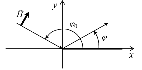
Let us consider two types of wave excitation: TH-polarization or TE- polarization (magnetic field vector \(\tilde{H}\) or electrical field vector \(\tilde{E}\) is perpendicular to the edge, correspondingly).
2. Construction of a heuristic solution for TH-polarization
2.1. Development of a verification solution
Consider the problem of electromagnetic wave diffraction on an impedance half-plane. The boundary conditions for the case of TH-polarization (vector \(\tilde{H}\) is perpendicular to the edge) have the form [9 – 16]:
$$\begin{cases}
H_{x+}-H_{x-}=-Z^{-1}E_z, \\
E_{z+}=E_{z-}=E_z \quad \text{when } y=0
\end{cases}
\tag{1}$$
where impedance Z=iX, X is a variable parameter, which the reflection coefficient depends on, and i is an imaginary unit. Here the signs “+” and “−” correspond to the regions y>0 and y<0, respectively (see Figure 1).
The reflection and transmission coefficients RTH and TTH for an unbounded half-plane with boundary conditions (1) on the surface can be written as follows:
$$R_{TH}(X,\rho_0)=\frac{-W_0}{W_0+2i\sin(\rho_0)\,X}, \qquad W_0=120\pi
\tag{2}$$
$$T_{TH}=1+R_{TH} \tag{3}$$
The verification solution:
$$f_r(X,\varphi,\varphi_0) \tag{4}$$
is obtained employing the Wiener-Hopf method [9 – 13].
2.2. Selection of primary heuristic formulas
We choose primary heuristic formulas as in [8]:
$$f_g(R,T,\varphi,\varphi_0)
=\frac{1}{2}
\left(
\frac{1-T}{-\cos\!\left(\frac{\varphi-\varphi_0}{2}\right)}
+
\frac{R}{-\cos\!\left(\frac{\varphi+\varphi_0}{2}\right)}
\right)
\tag{5}$$
$$f_g^{0}(R,T,\varphi,\varphi_0)
=\frac{1}{2}
\left[
\frac{(1-T)\sin\!\left(\frac{\varphi-\varphi_0}{2}\right)}
{-\cos\!\left(\frac{\varphi-\varphi_0}{2}\right)}
+
\frac{R\sin\!\left(\frac{\varphi+\varphi_0}{2}\right)}
{-\cos\!\left(\frac{\varphi+\varphi_0}{2}\right)}
\right]
\tag{6}$$
In (5) and (6): R=RTH, T=TTH. When X=0: RTH=−1, TTH =0, and expressions (5), (6) are transformed into known expressions f , f 0 from [17 – 19]. Formula (5) corresponds to the generalized diffraction coefficients (GDC) approximation, and formula (6) corresponds to the physical optics diffraction coefficients (PODC) approximation [8].
2.3. Carrying out the adjustment procedure
The adjustment procedure consists in comparing the heuristic formula (5) with the Wiener-Hopf solution (4) [9]. At the first stage, we compare the functions (4) and (5) and empirically find the semitransparency function depending on (X, φ) [10, 11], which allows us to bring the primary formula closer to a rigorous solution:
$$\mathrm{cxf}(X,\varphi)
=1-x(X)\left\{1-\cos\!\left[\frac{\pi-\varphi}{1+x(X)}\right]\right\}
\tag{7}$$
$$x(X)=1-\exp\!\left(-\frac{X}{W_0}\right)
\tag{8}$$
$$f_h(R,T,\varphi,\varphi_0)
=f_g(R,T,\varphi,\varphi_0)\,
\frac{\mathrm{cxf}(X,\varphi_s)}{\mathrm{cxf}(X,\varphi)}
\tag{9}$$
Here, cxf(X, φs) is the function cxf(X, φ) value at the singularity point angle φs = π − φ0, that is disposed on the boundary between light and shadow.
3. Construction of a heuristic solution for TE-polarization
3.1. Development of a verification solution
The boundary conditions for the case of the incidence of a TE-polarized wave (vector is perpendicular to the edge) on an impedance half-plane have the form [9 – 16]:
$$\begin{cases}
Z\left(H_{z+}-H_{z-}\right)=E_x, \\
E_{x+}=E_{x-}=E_x \quad \text{when } y=0
\end{cases}
\tag{10}$$
The geometry of the problem is depicted in Figure 2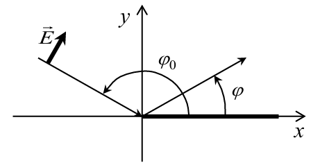
The reflection and transmission coefficients RTE and TTE for an unbounded half-plane with boundary conditions (10) on the surface can be written as follows:
$$R_{TE}(X,\varphi_0)
=\frac{W_0}{W_0+2i\sin(\varphi_0)\,X}, \qquad W_0=120\pi
\tag{11}$$
$$T_{TE}=1-R_{TE}
\tag{12}$$
The verification solution:
$$g_r(X,\varphi,\varphi_0) \tag{13}$$
is obtained employing the Wiener-Hopf method [9 – 13].
3.2. Selection of primary heuristic formulas
Primary heuristic formulas we choose as in [8]:
$$g_f(R,T,\varphi,\varphi_0)
=\frac{1}{2}
\left(
\frac{1-T}{-\cos\!\left(\frac{\varphi-\varphi_0}{2}\right)}
+
\frac{R}{-\cos\!\left(\frac{\varphi+\varphi_0}{2}\right)}
\right)
\tag{14}$$
$$g_f^{0}(R,T,\varphi,\varphi_0)
=\frac{1}{2}
\left[
\frac{(1-T)\sin\!\left(\frac{\varphi-\varphi_0}{2}\right)}
{-\cos\!\left(\frac{\varphi-\varphi_0}{2}\right)}
+
\frac{R\sin\!\left(\frac{\varphi+\varphi_0}{2}\right)}
{-\cos\!\left(\frac{\varphi+\varphi_0}{2}\right)}
\right]
\tag{15}$$
In (14) and (15): R=RTE, T=TTE. When X=0: RTH =1, TTH =0, and expressions (14), (15) are transformed into known expressions g, g 0 from [17 – 19]. The difference between formulas (14), (15) and formulas (5), (6) is that we substitute different values of R and T into each one. Formula (14) corresponds to the GDC approximation, and formula (15) corresponds to the PODC approximation [8].
3.3. Carrying out the adjustment procedure
Just as for the case of the TH polarization described in sub-section 2.3, we empirically select the semitransparency function depending on (X, φ) [10, 11] for the ТЕ- polarization:
$$\mathrm{cxg}(X,\varphi)=\left[\sin\!\left(\frac{\varphi}{2}\right)\right]^{x(X)},
\qquad
x(X)=1-\exp\!\left(-\frac{X}{W_0}\right)
\tag{16}$$
Heuristic formula for TE- polarization:
$$g_h(R,T,\varphi,\varphi_0)
=g_f(R,T,\varphi,\varphi_0)\,
\frac{\mathrm{cxg}(X,\varphi)}{\mathrm{cxg}(X,\varphi_s)}
\tag{17}$$
Here also cxg(X, φs) is the function cxg(X, φ) value at the singularity point angle φs = π − φ0, that is disposed on the boundary between light and shadow.
4. Calculation results
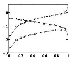
Figure 3 depicts the calculation results for TH-polarization at φ=90º and different values of Х.
A study of the behavior of the functions whose graphs are depicted in Figure 3 showed that as the parameter X changes from 0 to infinity, the shapes of curves GDC (5) and PODC (6) remain unchanged, while curves (4) and (9) shift from the curve (5) to curve (6).
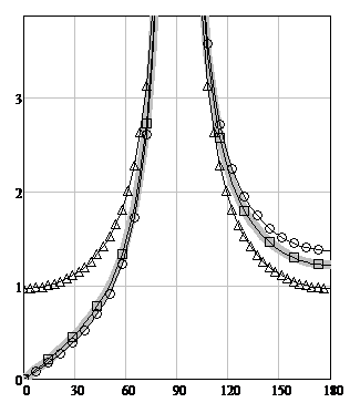
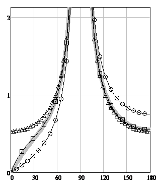
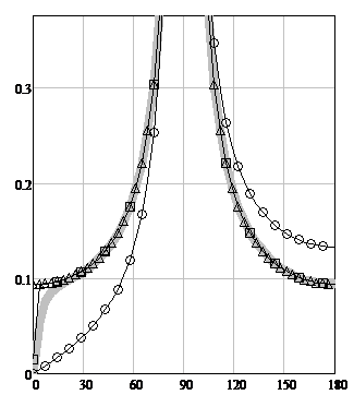
Figure 3: The TH-polarization scattering diagrams modules for φ0= 90º. The angle φ is plotted horizontally. The scattering diagrams (SD) modules are plotted vertically. The solid gray line is WHM solution fr(X, φ, φ0) (4}, circles are the GDC formula (5), triangles are the PODC formula (6), squares are the heuristic solution fh(R, T, φ, φ0) (9).
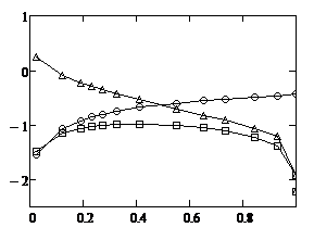
A study of the behavior of the functions whose graphs are depicted in Figure 4 showed that as the parameter X changes from 0 to infinity, the shapes of curves GDC (14) and PODC (15) remain unchanged, while curves (13) and (17) shift from the curve (14) to curve (15).
Figure 4 illustrates the calculation results for TE-polarization at Х=100, φ=90º.
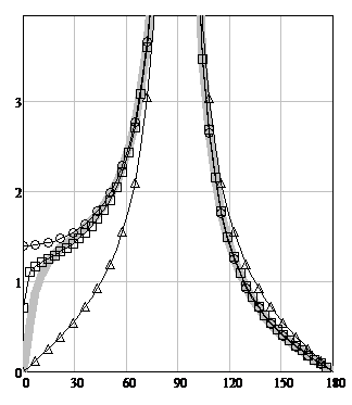
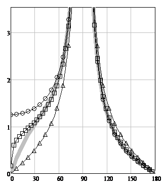
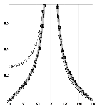
Figure 4: The TE-polarization scattering diagrams modules for φ0= 90º. The angle φ is plotted horizontally. The scattering diagram (SD) modules are plotted vertically. The solid gray line is WHM solution
gr(X, φ, φ0) (13), the circles are the GDC formula (14), triangles are the PODC formula (15), squares are the heuristic
solution gh(R, T, φ, φ0) (17).
5. Quantification of accuracy
Quantification of accuracy was carried out employing formulas, which we will call “functions L“:
$$L_{fh}(R,T,\varphi,\varphi_0)
=\lg\!\left(
\frac{1}{2\pi}
\int_{0}^{2\pi}
\left|
\frac{f_r(X,\varphi,\varphi_0)}{f_h(R,T,\varphi,\varphi_0)}
-1
\right|
\,d\varphi
\right)
\tag{18}$$
$$L_{fg}(R,T,\varphi,\varphi_0)
=\lg\!\left(
\frac{1}{2\pi}
\int_{0}^{2\pi}
\left|
\frac{f_r(X,\varphi,\varphi_0)}{f_g(R,T,\varphi,\varphi_0)}
-1
\right|
\,d\varphi
\right)
\tag{19}$$
$$L_{fg^{0}}(R,T,\varphi,\varphi_0)
=\lg\!\left(
\frac{1}{2\pi}
\int_{0}^{2\pi}
\left|
\frac{f_r(X,\varphi,\varphi_0)}{f_g^{0}(R,T,\varphi,\varphi_0)}
-1
\right|
\,d\varphi
\right)
\tag{20}$$
$$L_{gh}(R,T,\varphi,\varphi_0)
=\lg\!\left(
\frac{1}{2\pi}
\int_{0}^{2\pi}
\left|
\frac{g_r(X,\varphi,\varphi_0)}{g_h(R,T,\varphi,\varphi_0)}
-1
\right|
\,d\varphi
\right)
\tag{21}$$
$$L_{gf}(R,T,\varphi,\varphi_0)
=\lg\!\left(
\frac{1}{2\pi}
\int_{0}^{2\pi}
\left|
\frac{g_r(X,\varphi,\varphi_0)}{g_f(R,T,\varphi,\varphi_0)}
-1
\right|
\,d\varphi
\right)
\tag{22}$$
$$L_{gf^{0}}(R,T,\varphi,\varphi_0)
=\lg\!\left(
\frac{1}{2\pi}
\int_{0}^{2\pi}
\left|
\frac{g_r(X,\varphi,\varphi_0)}{g_f^{0}(R,T,\varphi,\varphi_0)}
-1
\right|
\,d\varphi
\right)
\tag{23}$$
Each of the functions L is a quantitative integral estimate of the accuracy of the function in the denominator of the integrand on a logarithmic scale. The smaller the value of a function L is, the closer the corresponding function in the denominator of the integrand is to the verification solution.
Graphs quantitatively describing the deviations of heuristic approximations from the rigorous solution for TH- polarization are depicted in Figure 5.
Graphs quantitatively describing the deviations of heuristic approximations from the rigorous solution for TE- polarization are depicted in Figure 6.
6. Physical interpretation of the solution
As X changes from 0 to ∞, the following changes occur: the expression fh(R, T, φ, φ0) (9) transforms from the formula fg(R, T, φ, φ0) (5) to the formula fg0(R, T, φ, φ0) (6), and the expression gh(R, T, φ, φ0) (17) transforms from the formula gf (R, T, φ, φ0) (14) to the formula gf 0(R, T, φ, φ0) (15).
This means that the greater the transparency of the object is, the more the formulas for the GDC approximation (5), (14) are transformed into formulas for the PODC approximation (6), (15). This property can be used in the future to build primary heuristic formulas for semi-transparent objects.
Thus, none of the approximations GDC or PODC taken separately gives satisfactory solution in the entire range of values of the parameter X [8, 9, 11].
7. Non-transparent half-plane
As an additional illustration of the capabilities of the MFC, we present the calculated data for solving the problem of diffraction of a TH-polarized electromagnetic wave on a non-transparent half-plane [11, 20]. Generalized bilateral impedance boundary conditions (GBIBC), for which boundary conditions (1) are a special case, lead to the following expressions for the diffraction coefficient:
$$f_{gH}(R,T,\varphi,\varphi_0)
=\frac{1}{2}
\left(
\frac{1}{-\cos\!\left(\frac{\varphi-\varphi_0}{2}\right)}
+
\frac{1-2\,\arg(R)/\pi + C}
{-\cos\!\left(\frac{\varphi+\varphi_0}{2}\right)}
\right)
\tag{24}$$
Here R is the reflection coefficient depending on the parameter X1, similar to X [11, 20], С is a small parameter for additional accuracy correction. In further work in accordance with the MFC concept on the heuristic formula (24), in order to apply it in a specific practical problem, the parameter C should either be distributed over other components of the heuristic formula (24), or turned into a basic component that has a physical meaning. In accordance with the GBIBC, in (24) for all X values [20]: |R|=1, T=0, i.e. the half-plane is completely non-transparent, and only the phase of the reflection coefficient R changes. The graphs of the behavior of the function (24) are depicted in Figure 7.
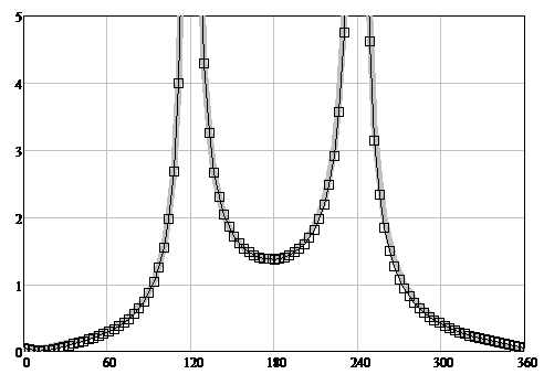
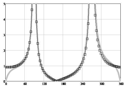
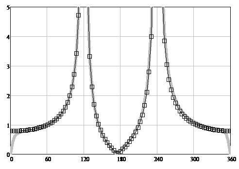
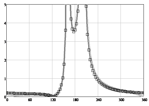
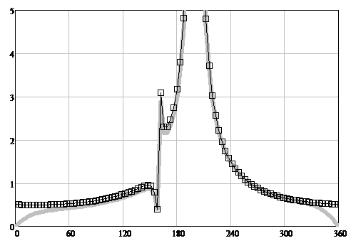
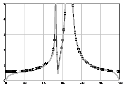
Figure 7: The TH-polarization scattering diagrams modules. The angle φ is plotted horizontally. The scattering diagrams (SD) modules are plotted vertically. The solid gray line is WHM solution [11, 20], the squares are the heuristic solution fgH(R, T, φ, φ0) (24).
7.1. Physical interpretation of the heuristic solution of the problem of diffraction on a non-transparent half-plane
For TH-polarization, as a result of the change in the phase of the reflection coefficient R as the parameter similar to X changes from 0 to ∞, the transformation takes place: f → g [11, 20].
8. Discussion
In this article, heuristic formulas are obtained for solving problems of diffraction on a semitransparent half-plane. A refinement over the GDC and PODC approximations was found employing the method of fundamental components (MFC). Heuristic formulas similar to GDC have been proposed many years ago [21, 22], although they were applied without an adjustment procedure.
Obtaining refined heuristic solutions for two-dimensional scatterers with non-ideal boundary conditions is a topical problem [23 – 26]. Such solutions are obtained even in the presence of reliable numerical solutions that can be used for verification of the mentioned heuristic formulas. The purpose of obtaining refined heuristic solutions is to use them in solvers designed for resource-intensive practical problems.
Together with heuristic approaches that describe the shape of the contour and edge profile, as well as the influence of the far zone condition [6, 8], the approach that describes the influence of boundary conditions complements the set of fundamental components that allows you to build effective heuristic formulas for three-dimensional objects of complex shape and with various boundary conditions.
In addition to refining the primary heuristic formulas, the MFC can be used to correct the numerical solution based on the experimental results. Such a need may arise in those cases when, due to inaccurate input data, the numerical calculation diverges from the experimental results. Engineering approaches of this kind are already widely used, however, unlike MFC, they are usually not based on primary heuristic formulas which have a physical meaning that helps to understand the reasons for the discrepancies between theory and experiment.
The MFC approach can be used to calculate diffraction for large 3D objects, for which it is impossible to obtain a numerical solution. The procedure for adjusting the heuristic solution is carried out on a smaller size scatterer. Having achieved the required accuracy, one can further apply the heuristic formula for a larger scatterer, which can no longer be calculated by rigorous numerical methods. In this case, the performance of heuristic formulas will not change, and the accuracy will even increase compared with the smaller size scatterer.
The direction of future research is to apply the technique proposed in this article to objects of different shapes and with different boundary conditions. In the future, such solutions can significantly increase the speed of solvers and give them new opportunities for solving practical problems.
9. Conclusions
The article proposes a technique for improving the accuracy of primary heuristic formulas employing the adjustment procedure. The technique has been verified for boundary conditions of certain types. However, this approach can be just as well applied to a half-plane with arbitrary boundary conditions, provided that a verification solution is available.
Conflict of Interest
The author declares no conflict of interest.
Acknowledgment
The author is grateful to Dr. Sci. S.E. Bankov for providing programs for verification and analytical expressions for R, T.
- U. Jakobus, “Overview of hybrid methods in FEKO: Theory and applications,” 2010 International Conference on Electromagnetics in Advanced Applications, 2010, pp. 434-437, doi: 10.1109/ICEAA.2010.5653159
- Hönl, H.; Maue, A.W.; Westpfahl, K. Handbuch der Physik; Flügge, S., Ed.; Springer: Berlin/Heidelberg, Germany, 1961; Mir: Moscow, Russia , 1964; Volume 25/1 , p. 218.
- Kravtsov, Y.A.; Zhu, N.Y. Theory of Diffraction: Heuristic Approaches; Alpha Science Int.: Oxford, UK, 2010
- James, G.L. Geometrical Theory of Diffraction for Electromagnetic Waves; Peter Peregrinus Ltd.: London, UK, 1976.
- Borovikov, V.A.; Kinber, B.E. Geometrical Theory of Diffraction; IEEE: London, UK, 1994.
- M.V. Vesnik. The Method of the Generalized Eikonal. New Approaches in the Diffraction Theory (Walter de Gruyter, Berlin, 2015).
- M.V. Vesnik MV. Physical Interpretation of Strict Solutions of Diffraction Problems by Heuristic Relations. Journal of Mathematical Sciences, 239, 751–770 (2019). https://doi.org/10.1007/s10958-019-04324-8
- M.V. Vesnik, “New Possibilities for Constructing Heuristic Solutions to Problems of Electromagnetic Diffraction”, Eng 2022, 3, 27-41. https://doi.org/10.3390/eng3010004
- M.V. Vesnik, S.E. Bankov, “Heuristic solution to the problem of diffraction of a TE-polarized electromagnetic wave on a semitransparent half-plane”, Waves in Random and Complex Media, July 2021, DOI 10.1080/17455030.2021.1951888
- M.V. Vesnik, “Using the Method of Base Components for a Heuristic Solution to the Diffraction Problem on a Half-Plane with Nonideal Boundary Conditions”, J. Commun. Technol. Electron. 2019, 64, 1211–1217
- M.V. Vesnik, “Physical Interpretation of the Solution to the Problem of Diffraction on the Impedance Half-plane”, 2020 7th All-Russian Microwave Conference (RMC), Moscow, Russia, 2020, pp. 200-202, DOI: 10.1109/RMC50626.2020.9312342
- S.E. Bankov, Integrated Microwave Optics, (Fizmatlit, Moscow, 2018).
- B. Noble, Methods based on the Wiener – Hopf Technique for the Solution of Partial Differential Equations, London, 1958.
- Senior, T.B.A. Half plane edge diffraction. Radio Sci. 1975, 10, 645.
- Senior, T.B.A. Diffraction tensors for imperfectly conducting edges. Radio Sci. 1975, 10, 911.
- Voitovich, N.N.; Katsenelenbaum, B.Z.; Korshunova, E.N.; Pangonis, L.I.; Pereyaslavets, M.L.; Sivov, A.N.; Shatrov, A.D. Electromagnetics of Antennas with Semitransparent Surfaces. A Method of Constructive Synthesis; Nauka: Moscow, Russia, 1989.
- P.Y. Ufimtsev, Method of Edge Waves in the Physical Theory of Diffraction (Sovetskoe Radio, Moscow, 1962; US Air Force Foreign Technology Division, 1-1154, 1962).
- Ufimtsev, P.Y. Theory of Edge Diffraction in Electromagnetics; Tech Science Press: Encino, CA, USA, 2003. ISBN 0-9657001-7-8.
- Ufimtsev, P.Y. Fundamentals of the Physical Theory of Diffraction; John Wiley & Sons, Inc.: Hoboken, NJ, USA, 2007.
- S.E. Bankov, M.V. Vesnik, V.F. Kravchenko, “Heuristic Solution to the Diffraction Problem on a Superconducting Half-Plane”, Journal of Communications Technology and Electronics, 2020, Vol. 65, No. 4, pp. 398–405.
- Raman CV, Krishnan KS. The Diffraction of Light by Metallic Screens, Proc. R. Soc. Lond. A 1927 Vol.116 254-267; DOI: 10.1098/rspa.1927.0135. Published 1 October 1927
- Shmoys J. Diffraction by a Half-Plane with a Special Impedance Variation, IRE Trans. on Antennas and Propagation Vol.7, No.5, December 1959, pp.88 – 90
- Luebbers RJ. “Finite conductivity uniform GTD versus knife edge diffraction in prediction of propagation path loss”, IEEE Transactions on Antennas and Propagation, vol. AP-32, pp. 70–76, Jan. 1984
- Holm PD. A New Heuristic UTD Diffraction Coefficient for Nonperfectly Conducting Wedges, IEEE Transactions on Antennas and Propagation, vol. 48, NO. 8, August 2000
- El-Sallabi HM, Rekanos IT, Vainikainen P. “A New Heuristic Diffraction Coefficient for Lossy Dielectric Wedges at Normal Incidence”, IEEE Antennas and Wireless Propagation Letters, Vol. 1, 2002, pp. 165-168
- Soni S, Bhattacharya A. «New heuristic diffraction coefficient for modeling of wireless channel», Progress In Electromagnetics Research C, Vol. 12, 125 – 137, 2010
No related articles were found.