Experimental Methodology to Find the Center of Gravity of a Solid
(This article belongs to the Special Issue on Special Issue on Multidisciplinary Sciences and Advanced Technology (SI-MSAT 2022) and the Section Multidisciplinary – Materials Science (MLM))
Export Citations
Cite
Je, J. and Jekal, E. (2022). Experimental Methodology to Find the Center of Gravity of a Solid. Journal of Engineering Research and Sciences, 1(3), 148–152. https://doi.org/10.55708/js0103015
Joohoon Je and Eunsung Jekal. "Experimental Methodology to Find the Center of Gravity of a Solid." Journal of Engineering Research and Sciences 1, no. 3 (March 2022): 148–152. https://doi.org/10.55708/js0103015
J. Je and E. Jekal, "Experimental Methodology to Find the Center of Gravity of a Solid," Journal of Engineering Research and Sciences, vol. 1, no. 3, pp. 148–152, Mar. 2022, doi: 10.55708/js0103015.
The center of gravity of a three-dimensional object found through an experimental method can be made easier and faster than calculating the movement manually to make it look more natural in graphic computer images. In addition, in various sports such as skating, the score can be increased by appropriately moving the position of the center of gravity. Lastly, it is expected that it can be used even when the performance is high in the manufacturing process to increase the stability and speed of various means of transportation (eg, automobiles, airplanes, etc.).
1. Introduction
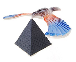
Tools or techniques using the center of gravity are deeply embedded in our daily lives [1, 2, 3]. For example, when creating animations, a motion generation technique that finds and moves the center of gravity of a character in order to provide a natural motion is considered an important task in the field of computer graphics [4, 5, 6, 7]. In addition, the traveling speed and fuel efficiency vary greatly depending on the load and the position of the center of gravity of the ship or airplane. In addition to this, as shown in Figure 1, there is also a simple toy that is balanced by the center of gravity when the beak is hung on the pedestal. In the case of this toy, it looks simple, but if one part breaks or other materials stick, it loses its center and collapses.
Therefore, this paper focused on the information of the center of gravity. The center of gravity information has enough advantages to be used as a parameter to determine the shape and motion of an object. First of all, the center of gravity can be expressed only in very small dimensions [8, 9, 10, 11]. Only the position values of the x, y, and z axes are required to indicate the position of the center of gravity in the coordinate system. In addition, many motions can be predicted even by changing the position of the center of gravity. For example, in the case of a walking motion, assuming that the y-axis is perpendicular to the ground, the position values in the x and z planes change, and the center of gravity vibrates with a very small width in the y-axis direction. The running motion is similar to the walking motion, but the speed in the x and z planes is different. The change in y value increases in jumping and squatting motions. In this paper, in order to create a more natural result in addition to the center of gravity information, motion history information is additionally utilized to increase the accuracy of pose prediction through the center of gravity. In addition, it can be used to increase the score by adjusting the position of the center of gravity in sports, or to increase speed and stability by adjusting the center of gravity of transportation means such as ships and airplanes [12, 13, 14].
2. Task description and data construction
The center of gravity is the center point of an object’s weight, and the center of mass is calculated based on the distribution of mass only. The difference is that the sum of the torques representing the action of the applied force to make it happen is zero. However, in special circumstances (such as the surface of the Earth) where gravity (mg) is constant, the center of gravity and the center of mass are the same. In everyday life, the center of gravity can be seen as equal to the balance point of an object. More specifically, if an object maintains its balance when a certain point is placed on a pointed pedestal, it can be said to be the center of gravity. Therefore, the center of gravity of a symmetrical object (sphere, regular polyhedron, etc.) with constant density coincides with the geometric center of the object.
2.1. Center of gravity of the plane
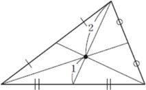
Center of gravity of the plane triangle The center of gravity of a triangle is the intersection of the medians, which are lines connecting one vertex of a triangle and the midpoint of its opposite side as shown in Figure 2.
For example, if the coordinates of the center of gravity G of a triangle ABC with three points as vertices are A(x1,y1), B(x2,y2),C(x3,y3), the center of the side BC is \(M(x’,y’),\;
x’ = \frac{x_2 x_3}{2},\;
y’ = \frac{y_2 y_3}{2}\) then the center of gravity G(x,y) is a point that divides the segment AM by 2:1. Mathematical coordinate can be obtained as equation(1) and (2).
$$
x
=
\frac{2x’ + 1x_1}{2 + 1}
=
\frac{2\left(\frac{x_2 + x_3}{2}\right) + x_1}{2 + 1}
=
\frac{x_1 + x_2 + x_3}{3}
\tag{1}
$$
$$
y
=
\frac{2y’ + 1y_1}{2 + 1}
=
\frac{2\left(\frac{y_2 + y_3}{2}\right) + y_1}{2 + 1}
=
\frac{y_1 + y_2 + y_3}{3}
\tag{2}
$$
Therefore, the coordinates of the center of gravity G is expressed as \(G\left(
\frac{x_1 + x_2 + x_3}{3},
\frac{y_1 + y_2 + y_3}{3}
\right)\)
Center of gravity of the plane n-polygon First, the center of gravity of a rectangle is a point obtained by dividing the rectangle into two triangles along the diagonal of the rectangle, finding the center of gravity of the triangles, and dividing the line segment made by connecting the points according to the ratio of the area of the triangle (for example, if the triangle Assuming that the area of is 1 and 3, respectively, the 3:1 point of the line segment made by connecting the center of gravity of the triangle is the center of gravity of the rectangle). The center of gravity of a pentagon is divided along a diagonal like a square to make three triangles, and then the center of gravity of the triangle made by connecting the centers of gravity of the triangles is the center of gravity of the pentagon. Shapes other than quadrilaterals and pentagons are divided into triangles and have centers of gravity, and if you repeat dividing the shapes again, a rectangle or a pentagon comes out.
2.2. Center of gravity of the solid
Since the z-coordinate value is added under the assumption that the triangle is three-dimensionally expressed in the three-dimensional space, the coordinates of the center of gravity G of the triangle ABC with the vertex A(x1, y1, z1), B(x2, y2, z2), C(x3, y3, z3) can be expressed as \(G\left(
\frac{x_1 + x_2 + x_3}{3},
\frac{y_1 + y_2 + y_3}{3},
\frac{z_1 + z_2 + z_3}{3}
\right)\). However, in the case of various three dimensional figures outside the triangle category, it is difficult to find them without using the center of mass using the integral taught in university physics. Therefore, in this pa- per, we try to find the center of gravity of a three-dimensional figure in a relatively simple and intuitive way.
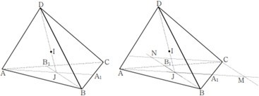
A point of mass placed at the vertex of a tetrahedron and the center of the inscribed sphere through mathematical proof A tetrahedron can be considered as an analogy of space for a triangle in a plane, and just as a triangle has an inscribed circle, a tetrahedron has an inscribed sphere.
Theorem Let I be the center of the inscribed sphere of the tetrahedron, and let J be the intersection of the straight line DI and the plane ABC. Then the following equation holds:
$$
IJ
=
\frac{
S_{JBC}\cdot IA
+
S_{JAC}\cdot IB
+
S_{JAB}\cdot IC
}{
S_{JBC}
+
S_{JAC}
+
S_{JAB}
}
\tag{3}
$$
Proof. Construct the segments AA1 and BB1 from the vertices A and B of the triangle ABC through the point J. First, let’s express CJ using JA and JB. To do this, construct a parallelogram CMJN by drawing a straight line parallel to JA and JB through point C. Then CJ CM CN.
At this time, since the triangles CA1 M and B1AJ are similar, it becomes \(\frac{CM}{BJ}
=
\frac{CA}{BA},
\qquad
\frac{CN}{JA}
=
\frac{CB}{AB}\) However, the ratio of CA1 and BA1 is equal to the ratio of the areas of triangles CAA1 and BAA1. In this case, since the areas of triangles CJA1 and BJA1 are the same, \(\frac{CA_1}{BA_1}
=
\frac{S_{JAC}}{S_{JAB}}\). For the same reason, \(\frac{CB_1}{AB_1}
=
\frac{S_{JBC}}{S_{JAB}}\).
In the end, \(CM
=
\frac{S_{JAC}}{S_{JAB}}\)is obtained from the equations \(\frac{CM}{BJ}
=
\frac{CA_1}{BA_1},
\qquad
\frac{CA_1}{BA_1}
=
\frac{S_{JAC}}{S_{JAB}}\), and it can be seen that \(CN
=
\frac{S_{JBC}}{S_{JAB}} \, JA\) in a similar way. Since CJ CM CN, it is JI −IJ on the right side of the equation, the equation is derived, considering that it is CI −IC on the left side. In theorm’s equation, the area S of the triangles JAB, JBC, and JAC can be expressed using the areas S JAB,S JBC,S JAC of the sides DAB, CAC, and DBC of the tetrahedron. Consider the volumes of the tetrahedron DABJ, DBCH, and DACJ in the Figure 3. If their bases are called faces JAB and JBC JAC, respectively, the height of these tetrahedra is the same as h, so the volume of the tetrahedron is \(\frac{S_{JAB}\,h}{3},
\qquad
\frac{S_{JBC}\,h}{3},
\qquad
\frac{S_{JAC}\,h}{3}\) respectively. On the other hand, if we take DAB, DAC, DBC as the base of these tetrahedrons, and consider the heights drawn from the point J to these surfaces, all of these heights will be the same (let the height be k),then the volume of the tetrahedron will be \(\frac{S_{DAB}\,k}{3},
\qquad
\frac{S_{DAC}\,k}{3},
\qquad
\frac{S_{JBC}\,k}{3}\), respectively. Eventually we can get the equation \(S_{DAB}\,\frac{k}{h}, \quad
S_{JBC}, \quad
S_{DBC}\,\frac{k}{h}, \quad
S_{JAC}, \quad
S_{DAC}\,\frac{k}{h}\) which becomes \(\frac{S_{JAB}\,h}{3},
\quad
\frac{S_{DAB}\,k}{3},
\quad
\frac{S_{JBC}\,h}{3},
\quad
\frac{S_{DAC}\,k}{3},
\quad
\frac{S_{JAC}\,h}{3},
\quad
\frac{S_{JBC}\,k}{3}\). Now, by substituting the obtained equations into the equation of theorm and rearranging them, we can get equation(4).
$$
IJ
=
\frac{
S_{DBC}\cdot IA
+
S_{DAC}\cdot IC
+
S_{DAB}\cdot IC
}{
S_{DBC}
+
S_{DAC}
+
S_{DAB}
}
\tag{4}
$$
3. Experimental method
3.1. Regular polyhedron
3.1.1. tetrahedron
Hang the thread to the center of gravity of each side and leave it there until it stops shaking, then put a dot at the intersection of the hanging thread and the paper. After that, switch sides and repeat. At this time, the position of the paper and the multifaceted tooth should not be changed, only the hanging side should be changed. At this time, if all points coincide, the center of gravity is the midpoint of each side and the point of intersection of the lines connecting the extension line of the single thread to the point and the intersection of the surface.

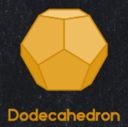
3.1.2. dodecahedron
It is the same as the experiment method of the tetrahedron, but in the case of the dodecahedron, a string is hung at each vertex instead of the center of gravity of each face. This is because in the case of a tetrahedron, if a perpendicular is drawn from a vertex, it meets the center of gravity of the face, but in a regular dodecahedron, if a perpendicular is drawn from a vertex, it continues to the opposite vertex. Therefore, after connecting the starting point of the thread to one vertex and hanging it, find the place where the opposite vertices meet and make a dot on the paper fixed to the floor. At this time, if all points coincide, it can be seen that the intersection line connecting each vertex and the furthest vertex is the center of gravity.
3.2. Car model
First, the part to be leveled in the erected form is found and marked on the upper part of the car model. Then, after turning it 90 degrees to the side, find the part to be leveled in the same way on the side part of the car model. Finally, after turning forward 90 degrees, find the part that is leveled, connect the intersections of the points, and check whether the point coincides with the center of mass.
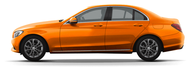
Table 1: The group of the distance between each dots in the tetrahedron model.
| Dot pairs | [1,2] | [1,3] | [1,4] | [2,3] | [2,4] | [3,4] |
| Distance (cm) | 0 | 0.5 | 0.7 | 0.5 | 0.7 | 0.4 |
4. Results
As shown in Figure 7, considering that the distance distri- bution is gathered and distributed within a maximum of 4.5cm, it can be seen that the experiment was elaborated enough to ignore the error. In addition, the experimental results fit well with the assumptions made mathematically at the beginning.
In Figure 8, we represent each number of dots of top, back, right, left and front as 1, 2, 3, 4 and 5.
According to e −1|θ|, the attribution degree is 0.778, in- put e into the cloud generator, activate the comment “better” and “very good”, and activate the degree of “very good” more than “better”, then the performance evaluation result of this type of man-portable is “very good “.Analysis and evaluation results can be obtained: protective index and self-measurement index cloud center of gravity vector deviation is large, indicating poor performance of the index, but the weight is low, the impact on the performance of the load is not significant, the improvement is not significant. The
Table 2: The group of the distance between each dots in the dodecahedron models.
| Dot pairs | [1,2] | [1,3] | [1,4] | [1,5] | [1,6] | [1,7] | [1,8] | [1,9] | [1,10] |
| Distance (cm) | 2.5 | 2.3 | 0.7 | 3.3 | 2.1 | 1.6 | 3.0 | 3.4 | 3.9 |
| Dot pairs | [2,3] | [2,4] | [2,5] | [2,6] | [2,7] | [2,8] | [2,9] | [2,10] | [3,4] |
| Distance (cm) | 1.6 | 2.5 | 1.3 | 1.9 | 0.8 | 0.8 | 1.2 | 1.6 | 1.9 |
| Dot pairs | [3,5] | [3,6] | [3,7] | [3,8] | [3,9] | [3,10] | [4,5] | [4,6] | [4,7] |
| Distance (cm) | 1.3 | 0.5 | 1.4 | 1.6 | 2.8 | 3.0 | 3.0 | 1.6 | 1.8 |
| Dot pairs | [4,8] | [4,9] | [4,10] | [5,6] | [5,7] | [5,8] | [5,9] | [5,10] | [6,7] |
| Distance (cm) | 3.1 | 3.1 | 4.1 | 1.8 | 1.9 | 1.7 | 1.9 | 2.1 | 1.7 |
| Dot pairs | [6,8] | [6,9] | [6,10] | [7,8] | [7,9] | [7,10] | [8,9] | [8,10] | [9,10] |
| Distance (cm) | 2.1 | 3.1 | 3.4 | 1.5 | 1.9 | 2.3 | 1.7 | 1.8 | 0.5 |
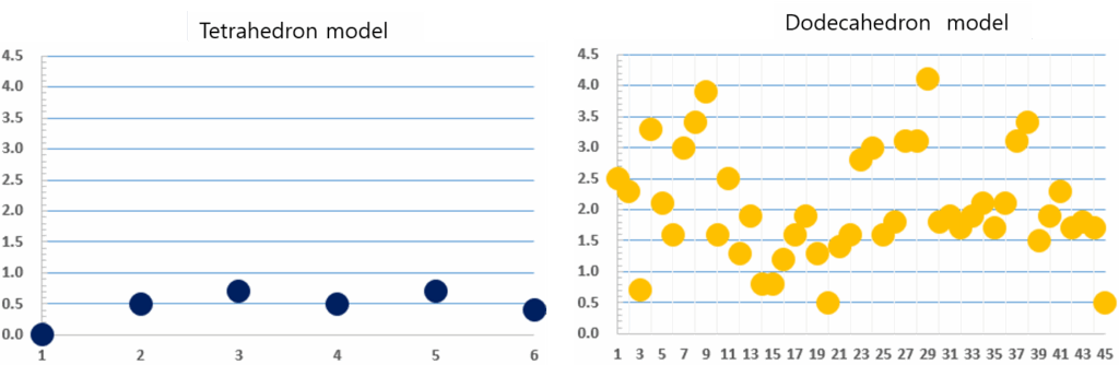
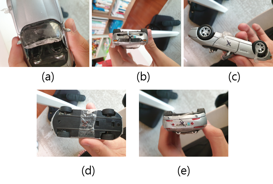
Table 3: The group of the distance between each dots in the car model.
| Dot pairs | [1,2] | [1,3] | [1,4] | [1,5] | [2,3] | [2,4] | [2,5] | [3,4] | [3,5] | [4,5] |
| Distance (cm) | 0.6 | 0.7 | 0.5 | 0.6 | 1.3 | 1.1 | 1.0 | 0.4 | 0.6 | 0.7 |
cloud center of gravity deviation of the three indicators of tactics, comfort, and manning effectiveness is similar to the system deviation, so the improvement of the performance of these three indicators can help this type of man-portable device improve its performance.
5. Conclusion
As mentioned in the introduction, these methods automatically calculate the motion of objects to make the motion in computer graphic images look more natural, making it easier and faster than manual work. In various sports such as skating, you can increase your score by moving the center of gravity appropriately. In addition, it can be used when the performance is high in the manufacturing process to increase the stability and speed of various means of transportation (eg, automobiles, airplanes, etc.).
6. Limitations
Our research presents the final design of a low-cost device with reliable and accurate performance. Though it would be interesting to compare our device with other similar ones, it is challenging to replicate the same device(s) and scenarios used by other researchers. Future research could involve a comparative study involving our device and other similar devices to assess their relative performance and usability and to gain further insights into the development of low-cost devices that can simulate the weight of virtual objects and changes in their center of gravity. Any electronic system communication can potentially have transmission delays. However, we did not calculate this delay because the time for communication was of a smaller magnitude than the the time used for the system to be filled. Also, our system was faster than other reported state-of-the art system.
In our experiments, the perception was based on a single sample from each participant. We did this because we observed in pilot studies that, after a few repetitions of the same trials, fatigue could kick in and could affect their responses. However, the results we had were consistent among themselves, showing errors were committed by a similar number of participants, and independent participants often chose similar answers. As such, to a large extent, our approach is valid, as the performance of the final complete prototype linked to the VR application shows.
- H. Uitenbroek, “The accuracy of the center-of-gravity method for measuring velocity and magnetic field strength in the solar photosphere”,, The Astrophysical Journal, vol. 592, no. 2, p. 1225, 2003,
6. - A. Üsküdar, Y. S. Türkan, Y. S. Özdemir, A. H. Öz, “Fuzzy ahp-center of gravity method helicopter selection and application”, “2019 8th International Conference on Industrial Technology and Management (ICITM)”, pp. 170–174, IEEE, 2019, doi:10.1109/ICITM.2019.8710703.
- B. Khorshidi, “A new method for finding the center of gravity of polygons”, Journal of Geometry, vol. 96, no. 1-2, pp. 81–91, 2009, doi: https://doi.org/10.1007/s00022-010-0027-1.
- M. Murray, A. Seireg, R. Scholz, “Center of gravity, center of pressure, and supportive forces during human activities”, Jour- nal of applied physiology, vol. 23, no. 6, pp. 831–838, 1967, doi: https://doi.org/10.1152/jappl.1967.23.6.831.
- Shermukhamedov, K. Baynazarov, “Graphic-analytical method for calculating the distribution of forces over the frame in the working process of the unloading”, Scientific-technical journal, vol. 4, no. 2, pp. 79–86, 2021, doi: https://uzjournals.edu.uz/ferpi/vol4/iss2/11.
- P. Wu, L. Zhou, H. Chen, H. Zhou, “An improved fuzzy risk analysis by using a new similarity measure with center of gravity and area of trapezoidal fuzzy numbers”, Soft Computing, vol. 24, no. 6, pp. 3923–3936, 2020, doi: https://doi.org/10.1007/s00500-019-04160-7.
- Y. Tsukamoto, S. Funatani, “Application of feature matching tra- jectory detection algorithm for particle streak velocimetry”, Jour- nal of Visualization, vol. 23, no. 6, pp. 971–979, 2020, doi: https://doi.org/10.1007/s12650-020-00677-4.
- uła, “The symmetric nature of
ion distribution of the human body center of gravity
during propelling manual wheelchairs with innovative propul- sion systems”, Symmetry, vol. 13, no. 1, p. 154, 2021, doi: https://doi.org/10.3390/sym13010154. - S. Zagorski, D. Andreatta, G. Heydinger, “Development of a passen- ger vehicle seat center-of-gravity measuring device”, Tech. rep., SAE Technical Paper, 2020, doi:https://doi.org/10.4271/2020-01-1061.
- P. Han, J. Zhang, L. Yang, “Research on active gravity center fault tolerance control of fuel system”, “Advances in Guidance, Nav- igation and Control”, pp. 5157–5164, Springer, 2022, doi: https://doi.org/10.1007/978-981-15-8155-7_425.
- R. Holubek, M. Vagaš, “Center of gravity coordinates estimation based on an overall brightness average determined from the 3d vision system”, Applied Sciences, vol. 12, no. 1, p. 286, 2022, doi: https://doi.org/10.3390/app12010286.
- B. Firmanto, A. F. O. Gaffar, B. Suprapty, A. B. W. Putra, et al., “Multi- modal biometric system based on feature source compaction and the proposed vcg (virtual center of gravity) feature”, “2021 International Seminar on Intelligent Technology and Its Applications (ISITIA)”, pp. 95–100, IEEE, 2021, doi:10.1109/ISITIA52817.2021.9502224.
- A. Brian, N. Getchell, L. True, A. De Meester, D. F. Stodden, “Recon- ceptualizing and operationalizing seefeldt’s proficiency barrier: Ap- plications and future directions”, Sports Medicine, pp. 1–12, 2020, doi:https://doi.org/10.1007/s40279-020-01332-6.
- A. Mohamed, “Gravity applications to groundwater storage varianal of Applied Geophysics, vol. 182,
,2020,doi:https://doi.org/10.1016/j.jappgeo.2020.104177.
No related articles were found.