Disinfecting Omnidirectional Mobile Robot with Vision Capabilities

(This article belongs to the Special Issue on Special Issue on Multidisciplinary Sciences and Advanced Technology (SI-MSAT 2022) and the Section Robotics (ROB))
Export Citations
Cite
Qaisar, W. , Riaz, M. T. , Basit, A. , Naseem, Y. and Nazir, Z. (2022). Disinfecting Omnidirectional Mobile Robot with Vision Capabilities. Journal of Engineering Research and Sciences, 1(3), 153–153. https://doi.org/10.55708/js0103016
Waqas Qaisar, Muhammad Tanveer Riaz, Abdul Basit, Yasir Naseem and Zohaib Nazir. "Disinfecting Omnidirectional Mobile Robot with Vision Capabilities." Journal of Engineering Research and Sciences 1, no. 3 (March 2022): 153–153. https://doi.org/10.55708/js0103016
W. Qaisar, M.T. Riaz, A. Basit, Y. Naseem and Z. Nazir, "Disinfecting Omnidirectional Mobile Robot with Vision Capabilities," Journal of Engineering Research and Sciences, vol. 1, no. 3, pp. 153–153, Mar. 2022, doi: 10.55708/js0103016.
The disinfecting mobile robot with omnidirectional movement is a vision-capable robot that uses image processing to follow a dedicated path regardless of the change in direction required and uses Ultraviolet rays from the UV light tubes to disinfect everything in its path and disinfect the entire room. The basic premise of the project in this paper is the principle of designing a mobile robot that has high mobility and can move in every direction to follow a dedicated path that can be used to disinfect certain places that are not feasible for human beings. This proposed project is an omnidirectional mobile robot that will be designed such that it will use controllers, a camera for image processing to avoid any obstacle in its path, and actuators all communicating with one another to rotate the wheels of the robot individually to achieve the desired linear and rotatory motion to avoid any obstacles in the path of the robot and clean all the bacteria and germs in the room that might be harmful to humans. All of these components work through feedback which is being given through an encoder to achieve the desired output motion of the robot. The main benefit of this disinfecting mobile robot will be its increased mobility due to the combined effect of its rotatory and linear motion. This increased mobility combined with a set of ultraviolet light rays and a camera in the front which uses image processing to detect any object in its path and avoid it to disinfect an entire targeted area and allow it to access areas where conventional robots and humans can’t go.
1. Introduction
The basic premise of this project is the principle of designing an omnidirectional mobile robot that uses image processing to detect its path and uses Ultraviolet rays to disinfect everything in its dedicated path. As we know that a mobile robot is a typical moving robot which uses sensors or cameras along with other technology to identify its surroundings and move around its environment and is controlled using a specific software. Mobile robots normally use a combination of wheels, tracks, and legs along with artificial intelligence (AI) and they are becoming increasingly popular across the different major business sectors of the world [1]-[5]. This proposed project is a mobile robot that will be designed such that it will use controllers, sensors, and actuators all communicating with one another to rotate the wheels of this robot individually to achieve the desired rotation to avoid any obstacles in the path of the robot [6]-[9]. The movement of the robot is done using omnidirectional caster wheels which are rotated using a motor [10]. But first, we shall discuss how we will use all these components together to form a closed-loop control system and achieve this end goal.
2. Methodology
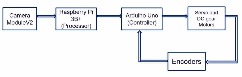
The primary component that will initiate this process of rotation of the wheel at a certain angle is the camera of this robot which will act as the sensor for this control system. The camera will act as the switch of this system because when the camera sees nothing and no information is being given to the microprocessor then the robot will continue to move in a straight path. But, as soon as some visuals are picked up by the camera of some obstacle in the way then it will convey that information to the microprocessor which will then do its function to avoid that particular obstacle.
The next component of this system to be activated after receiving the input signal from the sensor will be the microprocessor. The microprocessor which we are using in this system is a Raspberry Pi microprocessor and it will be programmed using python programming specifically for the type of actuators that will be attached to this system. The microprocessor in this system can be said to act as the messenger as it takes the signal from the input that is the camera and then uses that signal to the controller, for which we shall use an Arduino that will control the rotation of motors.
The image picked up by the camera module is processed by the microprocessor using python programming code embedded in it. The Raspberry Pi has a dedicated camera input port for recording HD video and high-resolution photos [11]-[13]. We will create tools that take photos and video and analyze them in real-time for the controller to understand the image signal using Python and specific libraries written for the Pi [14]. This is done by taking the input image in the form of RGB colors which are not in a readable format for the motor controller. The image data is a two-dimensional array of pixels, with each pixel representing a tuple of three values: the relative intensity of red, green, and blue colors in the range 0 to 255 [15]-[18]. This python code will access a specific pixel in the image by treating the image as an array and providing a tuple of the pixel’s x and y positions [19]. This will convert the image signal from the camera and transfer it to the microcontroller in a form that it will understand to control the Servo and DC gear motors that are used for the motion of this omnidirectional robot.
The final component of this system is actuators. Two kinds of motors are being used in this mobile robot them being the Servo motor and a simple DC gear motor. The reason for these two input actuators is because the Servo motors act as the steering motor and the DC gear motor acts as the driving motor for this omnidirectional mobile robot [20]. The actuators are controlled with the help of the controller and the processing is done by the microprocessor. After receiving the signal from the controller the DC gear motor will provide the driving motion for this robot and the steering will be done by the Servo motor as it will change its angle and subsequently the angle of the wheel according to the input signal taken from the camera in the form an image which will be then processed by the raspberry pi microprocessor.
2.1. Disinfecting mechanism in the Omnidirectional Robot
The omnidirectional motion of the robot is to make it self-aware such that it follows a dedicated path and avoids any obstacle that comes in its way. The reason for this path following is to disinfect the entire area which the robot covers as it moves around an entire room using ultraviolet light. The top of the robot will include a socket that will be able to attach Ultraviolet tubes in a circular manner which will kill any germs and viruses in the path around the robot and ultimately make the whole area safe for human beings [21]-[24]. Hence the disinfecting mechanism of this robot is a very effective and practical one and also very easy to implement even on an industrial scale.
Now, there are three basic categories of Ultraviolet radiation which are used for disinfecting purposes in mobile robots. The three categories are as follows.
- UV- A
- UV-B
- UV-C
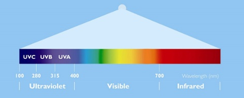
The type of Ultraviolet rays we are going to use for disinfecting purposes in our robot is the UV type C rays [25]-[28]. This is because the most effective and safe UV radiation for disinfecting is UV-C. The purpose of discussing all this is that a disinfecting mobile robot will move from one point to another and will stay at a particular distance from the wall and for some particular time it will exert UV radiation on the wall or a surface that we want to disinfect.
The purpose of discussing all of this is that that time the robot will take to disinfect the face independent of the RPM of the motor. Motor’s job is simply to carry the robot from one place to another for disinfecting.
3. Literature Review
In [29], the authors explained the Exploring the Applicability of Robot-Assisted UV Disinfection in Radiology. This robot has used this Ultraviolet disinfection technology in their robot to make a room completely germ-free. The robot designed in this paper has a wheeled mechanism along with sensors that allows it to move across a room and disinfect the entire area eliminating the use of current disinfecting methods which include using mops, and chlorine-based fluids by human cleaners.
This robot is very practical and our mobile robot aims to achieve a similar result but in a much better, and easier manner. Our robot uses a camera for path following and obstacle avoidance which increases the accuracy of our robot. Moreover, our robot uses very inexpensive parts like Caster wheels, and Arduino unlike the robot in this paper which uses mecannum wheels and an overall expensive and complicated mechanism to achieve the same result that our robot achieves with a less production cost.
In [30], the authors explained Motion Analysis and Control of Three-Wheeled Omnidirectional Mobile Robot. This is a three-wheel mobile robot with all three wheels being active omnidirectional wheels. The wheel is used are mecannum wheels which have very low torque and a very low speed as compared to what we require in our system. Hence mecannum wheels are a very expensive and relatively ineffective tool for an obstacle-avoiding omnidirectional robot. To avoid this, we are using caster wheels that are relatively inexpensive and do the job fairly well to avoid obstacles in the path of the robot and to follow a dedicated path.
In [31], the authors explained Structures of the Omnidirectional Robots with Swedish Wheels. Swedish Wheels can be Elliptical Mecanum double wheel or Mecanum wheel with rotary rollers. We are not using any kind of Special wheels as we are using omnidirectional caster wheels. Caster wheels can rotate and translate and these wheels yield the same result as mecanum and omnidirectional wheels and caster wheels are more practical in addition to being relatively inexpensive as compared to Swedish wheels.
In [32], the author focuses on a robot that is capable of moving around an entire room and disinfecting it from germs using ultraviolet radiation type C and does it similarly to our omnidirectional disinfecting mobile robot. But, the design of this robot limits its mobility and restricts the robot from moving between tight spaces due to the robot having a massive base, and a large turning radius. Our robot on the other hand has a relatively small base and three 360 degrees rotating wheels which enables it to rotate in very tight spaces. This makes our omnidirectional robot much more practical, especially for hospitals where there are many tight spaces between patient beds and robots such as proposed in this paper tend to see it very difficult to move in such spaces.
In [33], the authors explained a design of a three-wheel mobile robot with mecanum wheels. These wheels produce very high torque and can move in an omnidirectional manner. The working of these kinds of wheels is very complex and can be very hard to control using simple DC motors. The robot in this paper is also using an ARM Cortex-M4 microcontroller which is incapable of being connected to a camera for image processing purposes. Our design on the other hand uses an Arduino and a Raspberry Pi which work in serial communication and are capable of connecting any kind of sensor or camera with our robot.
In [34], the authors explained the wheel mechanism in this mobile robot uses an AC servo motor with magnetic clutches for driving the wheel and steering shaft. The magnetic clutch mechanism is a very impractical approach for our robot due to its high initial cost and the overheating of the clutches.
The clutch and gear system can be very useful in a lot of scenarios but cannot be controlled using image processing techniques. To compensate for this deficiency of magnetic clutches, our design uses three motors (One for each wheel) which are controlled using an Arduino according to the commands given to it by the Raspberry Pi.
In [35], the authors explained mobile robot consists of three active wheels. We are not using any kind of Special wheels, we are using motors to control simple wheels which can provide the best result as compared to these mecanum wheels.
The design of caster wheels being controlled using motors for each wheel is a very practical one due to its inexpensive nature and ease with which the entire mechanism can be assembled and controlled.
In [36], the authors explained the system in this paper is very efficient in terms of what is said to achieve. But it only rotates the wheel at 180 degrees while our requirement is for a 360-degree rotation mechanism. If the load on this system increases then motors of higher power will be required. The components used in the design of this robot include a bearing, chain drive, DC motor, sprocket, Steering, and wheel.
Our design of an omnidirectional robot on the other hand is a relatively simple one and is also easier to implement and produces a rotation of a full 360 degree to help the robot avoid any obstacle in its way.
In [37], the authors explained the Design of 360-degree rotating car aided for parking. The robot in this paper uses a locking mechanism and rotates the entire robot by lifting it for parking purposes while our system will use a microprocessor to control the movement of motors and rotate the wheels to follow a dedicated path.
The robot in this paper has very little practicality as the lifting and rotating mechanism can be used for very little practical use in our everyday lives and it also cannot be implemented on a much larger scale. Our omnidirectional path following robot, on the other hand, is a very practical one and has a wide array of uses in hospitals, and labs for disinfecting purposes and it can also be implemented on an industrial level.
In [38], the authors explained Intelligent disinfection robots assist medical institutions in controlling environmental surface disinfection. This robot uses a machine vision algorithm for the movement of the robot as a dedicated path is fed into the robot memory and it follows it and uses UV rays to disinfect the entire area from any germs and viruses [39].
Our robot on the other hand uses cameras, and image processing techniques to detect any object in its way and follow a dedicated path and continue to move without any interruption whereas the robot in this paper can be very inaccurate if an object comes in its way and it may stop the disinfecting process entirely due to a lack of sensors. Moreover, the material and circuitry required for this robot are very expensive and impractical to manufacture on a large scale whereas our robot uses normal electronics which are relatively inexpensive and allow for large-scale manufacturing.
4. Calculations and Analysis of three-wheel omnidirectional robot
4.1. RPM Calculation of motor
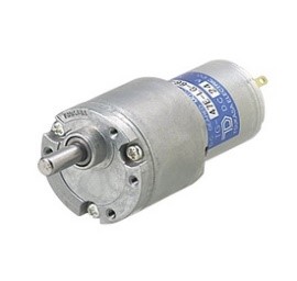
Motor that we are using for our project is TG-47E-LG having 753 rpm
Formulas Used
To calculate the Wheel travel with this motor we use
WT= 2πr (1)
where:
WT= Wheel Travel
Π= 3.14
r= radius of wheel
The radius of our specific wheel is 0.0325 m
Hence
WT= 0.2041 m
To calculate the desired velocity we use
s= v x t (2)
where:
s= distance traveled
v= desired velocity
t= time taken to travel distance
By rearranging we get:
v= s/t
For s=2 and t=1
v= 2 ms-1
For the desired RPM using our desired velocity we use:
RPM= (v x WT) x 60 (3)
Hence
RPM = 587
where 587 means that it will be almost 80% of 753 which is the rated speed of motor. Hence, 80% of 255 is 204, this means that we require 204 value of PWM in our Arduino to rotate the motor at our desired speed according to our wheel.
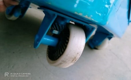
4.2. Kinematic Analysis
For kinematic analysis we are going to consider the omnidirectional wheel we are using for achieving the omnidirectional movement. The wheel we are using looks like:
The calculation of the kinematic of the wheel is done as:
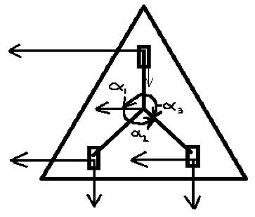
Our goal is to find the rolling and sliding constraints where:
θ = Wheel rotation
r = Wheel radius
Speed of wheel = v = r x θ
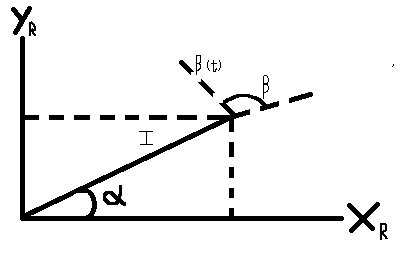
Translational Motion of Robot Motion is given by:
$$\zeta = \left[ \dot{x}\; \dot{y}\; \theta \right]^{T}$$
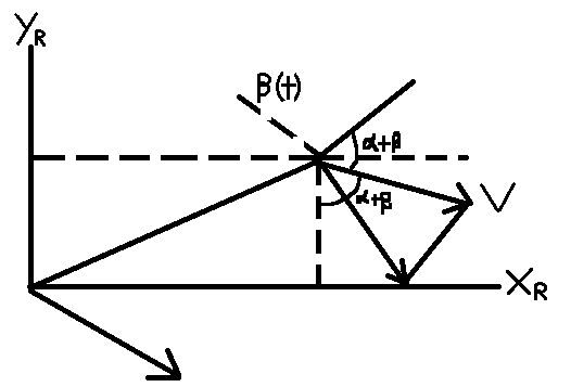
vx = sin(α + β)
vy = -cos(α + β)
[vx vy] = [sin(α + β) – cos(α + β)]
\(V_1
=
\begin{bmatrix}
v_x & v_y
\end{bmatrix}
\begin{bmatrix}
\dot{x} \\
\dot{y}
\end{bmatrix}\)
\(V_1
=
\begin{bmatrix}
\sin(\alpha+\beta) & -\cos(\alpha+\beta)
\end{bmatrix}
\begin{bmatrix}
\dot{x} \\
\dot{y}
\end{bmatrix}\)
Rotational Motion = -l x θ̇ = -l . cos (β̇) . θ̇
By Combining:
v = r x θ = sin(α + β) ẋ – cos(α + β) ẏ – l . cos (β̇) . θ̇
We can write it as:
$$
\sin(\alpha+\beta)\,\dot{x}
–
\cos(\alpha+\beta)\,\dot{y}
–
l\cos(\beta)
\begin{bmatrix}
\dot{x} \\
\dot{y} \\
\theta
\end{bmatrix}
–
r\,\theta
=
0
$$
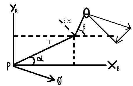
This gives us:
sin(α + β) ẋ – cos(α + β) ẏ – l . cos (β̇̇) . ζ – r . θ̇̇̇̇̇ = 0
Which is the rolling constraint.
Similarly our Sliding constraint is
[cos(α + β) . sin(α + β)d + l . sinβ]. R . ζ̇ + d . β
where
d = offset from the wheel axis
β = Variable steering
4.3. Dynamic Analysis:
The Dynamic analysis of this omnidirectional robot is going to be derived by using the Euler – Lagrange method:
L = K.E – P.E
where:
K.E = Kinetic Energy
P.E = Potential Energy
Our mobile robot will be derived by considering the surface of its movement to be planar, hence:
P.E = 0 J
The Lagrange dynamic formulation is described as:
$$
Y
=
\frac{d}{dt}\left(\frac{\partial L}{\partial \dot{q}}\right)
–
\frac{\partial L}{\partial q}
$$
Now mw, m1, mp are the mass of wheel, mass of link and the mass of platform respectively.
Iw, I1, Imp are the inertial of wheel, link and platform respectively.
Vwi, V I 1 are the linear velocity of wheel and a link at t.
Ωwi, Ω I 1 are the angular velocity of wheel and a link at t.
Vp, Ωp are the linear and angular velocities of the platform.
$$
K_{wi}
=
\frac{1}{2} m_w \, \mathbf{v}_{wi}^{T} \mathbf{v}_{wi}
+
\frac{1}{2} I_w \, \boldsymbol{\Omega}_{wi}^{T} \boldsymbol{\Omega}_{wi}
$$
For Wheel:
$$
K_{li}
=
\frac{1}{2} m_l \, \mathbf{v}_{li}^{T} \mathbf{v}_{li}
+
\frac{1}{2} I_l \, \boldsymbol{\Omega}_{li}^{T} \boldsymbol{\Omega}_{li}
$$
For link:
$$
K_p
=
\frac{1}{2} m_p \, \mathbf{v}_p^{T} \mathbf{v}_p
+
\frac{1}{2} I_p \, \boldsymbol{\Omega}_p^{T} \boldsymbol{\Omega}_p
$$
For Platform:
Total Kinetic Energy is:
$$
K.E
=
\sum_{i=1}^{3} X_{wi}
+
\sum_{i=1}^{3} X_{li}
$$
The forward dynamic equation of motion is a relation between the activated torque of wheel (as input) and angular velocities of wheel (as output). The activated variable of wheel is angular velocity q̇x
q = [θx θy θz]
q̇ = [θx θy θz]
By using Lagrange:
$$
T_x
=
\frac{d}{dt}\left(\frac{\partial x}{\partial \dot{q}_x}\right)
–
\frac{\partial x}{\partial q_x}
$$
$$
\frac{\partial L}{\partial \dot{q}_x}
=
\begin{bmatrix}
\frac{\partial x}{\partial \theta_y} \\
\frac{\partial x}{\partial \theta_y} \\
\frac{\partial x}{\partial \theta_z}
\end{bmatrix},
\qquad
\frac{\partial L}{\partial q}
=
\begin{bmatrix}
\frac{\partial x}{\partial \theta_y} \\
\frac{\partial x}{\partial \theta_y} \\
\frac{\partial x}{\partial \theta_z}
\end{bmatrix}
=
\begin{bmatrix}
0 \\
0 \\
0
\end{bmatrix}
$$
This implies that:
Tx = M(qs).q̈ + Gx(qs , q x)
Tx = [Tx Ty Tz]T
G = [qs q x]T is neglected as it is very small
Ts = M(qs).q̈
Hence, we find the torque vector as function of angular wheel acceleration.
4.4. Robot Constraints Calculations
4.4.1. Rolling Constraints
$$
\left[
\sin(\alpha+\beta)
–
\cos(\alpha+\beta)
–
l\cos(\beta)
\right]
\begin{bmatrix}
\dot{x} \\
\dot{y} \\
\theta
\end{bmatrix}
=
r\,\Phi
$$
This gives us
sin(α + β) ẋ – cos(α + β) ẏ – l . cos (β̇̇) = r . Φ
sin(α + β) ẋ = r . Φ + cos (β̇̇) . Φ (4)
Now.
α = 120
β = 0
r = 3
Φ = 50
Putting values in equation (4), we get:
sin (120) ẋ = [3 (50) ] + [4 (cos (0))] . 50
0.866 ẋ = 350
ẋ = 350 / 0.866
ẋ = 404 cms-1
As the wheels are same with similar sizes and dimensions so the constraints are also the same for each wheel.
4.4.2. Sliding Constraints:
[cos (α + β) + sin (α + β) d + l sin β) β] + d. β = 0
After evaluation of our servo motor, we observe that our sliding constraints tend to move towards zero and at a certain point there are no sliding constraints in our wheel as there is no sliding after a certain point in the robot’s movement.
Forward Dynamics
T = M(qs) . q̈
where M(qs) = Mass and initial parameters.
q̈ = [ θx θy θz ]
$$
M
=
\begin{bmatrix}
M_1 & 0 & 0 \\
0 & M_2 & 0 \\
0 & 0 & M_3
\end{bmatrix}
$$
Ts = [ Tx Ty Tz ]
Now, both Ty and Tz are zero, hence after solving we get:
θ = 197 rad/s-1
5. Serial Communication between Raspberry Pi and Arduino
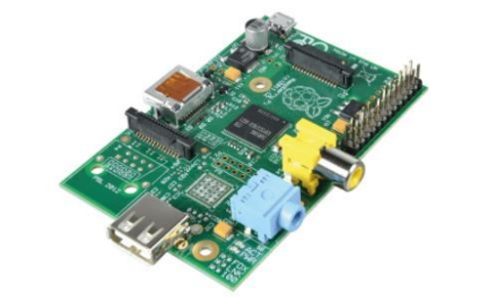
5.1. Raspberry Pi
A Raspberry Pi board is a fully functional computer with all the bells and whistles of a full-fledged computer, including dedicated memory, a processor, and a graphics card for output via HDMI. It even runs a specially designed version of the Linux operating system and is simple to install in most Linux software, and with little effort.
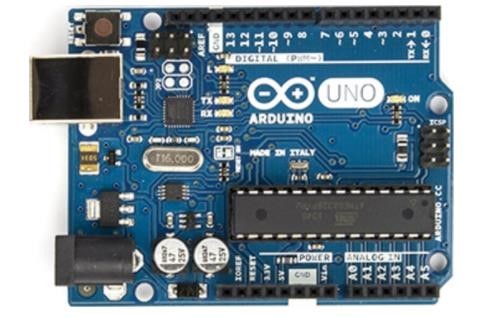
5.2. Arduino
Arduino is made up of three components. There is a hardware prototype platform, the Arduino language, as well as an IDE and libraries. The Arduino boards are not full-fledged computers, but rather microcontrollers. They don’t run a full operating system; instead, they write code and execute it as their firmware interprets it. The Arduino board’s primary function is to interface with devices and sensors, making it ideal for hardware projects in which you simply want things to respond to various sensor readings and manual input.
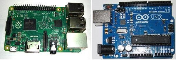
5.3. Arduino and Raspberry Pi
We are using Arduino with Raspberry Pi because of many factors like we are using some Analog Sensors in our prototype and due to the unavailability of Analog to Digital Converters in Raspberry Pi we are using it and we can also get a much better real-time response in Arduino. It is very easy to get started with Arduino due to the easy programming language and libraries availability that’s why we are controlling the actuators (DC and Servo Motors) and getting the real-time response from the sensors (Compass Sensors, Encoders, etc.) and using Raspberry Pi just for Path Tracking, Object Detection, and Distance Measurement.
5.4. Serial Communication between Arduino and Raspberry Pi
Now, due to the Raspberry Pi consisting only 26 GPIO Pins and no ADC channels, it cannot handle all of the interactions in projects like 3D printers. As a result, we require more output pins and additional functions, and in order to add more functions to PI, we must establish communication between PI and UNO. With this, we can use all of UNO’s functions as if they were PI functions.
5.5. Working and Programming Explanation:
Arduino Uno Part
In order to do programming we connect the Arduino with our computer or laptop t and then write the program in the Arduino IDE software, and then upload it to the UNO. Then, unplug the UNO from the PC. After programming, connect the UNO to the PI and connect an LED and a button to the UNO. The program now initializes the Arduino’s Serial Communication. When we press the UNO’s button, the UNO sends a few characters serially to the PI via the USB port. The PI’s LED blinks to indicate the characters being sent.
Raspberry Pi Part:
Following that, we must write a program for PI (see Code section below) to receive the data sent by UNO. To do so, we must first understand the commands listed below. We’ll import serial files from the library, and this function will allow us to send and receive data serially or via USB port.
Now we must specify the device port and bit rate in order for the PI to receive data from the UNO without errors. The following command enables serial communication at 9600 bits per second on the ACM0 port.
ser = serial.Serial(‘/dev/ttyACM0’, 9600)
Go to the PI terminal and look for the port to which the arduino is connected and then enter.
ls /dev/tty*
On the Raspberry Pi, you will then see a list of all attached devices. Connect the Arduino Uno to the Raspberry Pi using a USB cable and repeat the command. The displayed list makes it simple to identify the UNO attached port.
The following command is used to create a forever loop, which means that the statements inside the loop will be executed indefinitely.
While 1:
We will display the characters on the PI screen after receiving the data serially.
print (ser.readline())
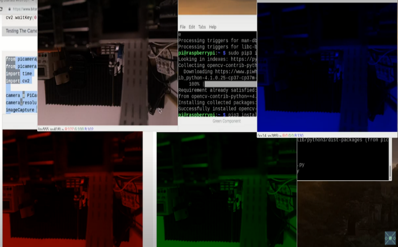
6. Image Processing
Image Processing is basically the use of computers to process digital images by using an algorithm or a programming code. It should be noted that every image is made up of several pixels whose pixel count is dependent on the resolution of the camera for a 640×480 resolution camera module there will be a total of 307,200 pixels make up the image in each frame for that particular camera. Each colored picture every frame is made up of three main colors them being Red, Green, and Blue. Now for a digital image representation:
- We need to know the position of each pixel in that image.
- We need to know the corresponding RGB values.
- This same process can be carried out for videos too as a video is just a series of images.
- All of this is carried out in our system using a raspberry pi board connected with a raspberry pi camera module V2.
Path planning is one of the most crucial things in any obstacle avoiding and path following mobile robot and this path planning is achieved through the process of image processing. For this, the first step is to enhance the image and to reduce noise to make the objects clear for the camera to detect and for this we are using histogram manipulation.
Segmentation in RGB vector space is simple. The goal of segmentation is to categorize each RGB pixel in a given image. Otsu’s method is used in image processing and computer vision to automatically reduce a grey level image to a binary image or to perform histogram shape based image shareholding.
Then we write programming using python on a raspberry pi module in such a way that uses this exact method to clarify each pixel and help the camera detect objects. After that, we do camera calibration as it is a necessary step in 3D computer vision to extract information from 2D images from the camera and we are using a method called the model plane method.
This technique only requires the camera to observe a planar pattern made up of a grid pattern in various orientations. Corner points are extracted for each view in order to calculate the correspondence between the model plane and its image. This helps the camera to detect the position of objects and send that information to the controller which then gives the command to rotate the servo motors accordingly.
6.1. Object Detection
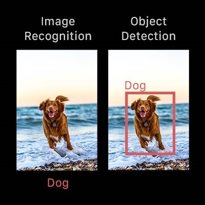
Object detection is a very important part of image processing when designing a vision-capable mobile robot. The reason is that the camera will detect any change in the reference frame and detect the presence of any object and then use the python coding to calculate the depth and distance of that object and then avoid it by giving the signal to the controller. As a result, object detection can be seen as a computer vision technique that enables us to recognize and locate objects in an image or video. Object detection can be used to count objects in a scene, determine and track their precise locations, and accurately label them using this type of identification and localization. Normally it is observed that the concepts of object detection and image recognition are frequently confused, so we must first distinguish between them in order to further learn about the working of image processing.
Image recognition is the process by which an image is labelled. The label “dog” is applied to a picture of a dog. A picture of two dogs is still labelled “dog.” Object detection, on the other hand, draws a circle around each dog and labels it “dog.” The model predicts where each object will be and what label will be assigned to it. Object detection, in this sense, provides more information about an image than recognition.
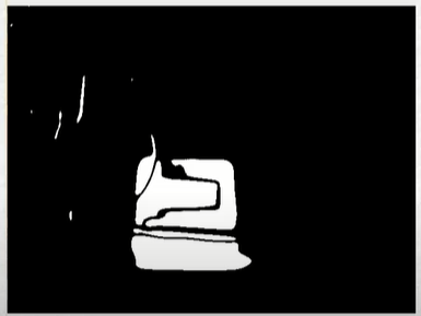
6.2. Object Detection Methodology
First, we take a reference image without the object to be focused and then take another image in the same frame with an object. Sample image is given as:
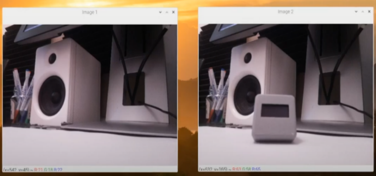
Secondly, this image is converted from colored to a greyscale image so that all the color characteristics are gone and now we only have two colors to work with them being black and white.
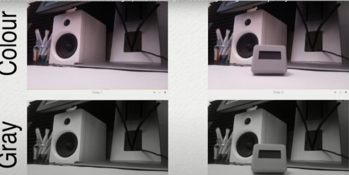
Then we subtract the two images to differentiate the object to be detecting from the surrounding environment.
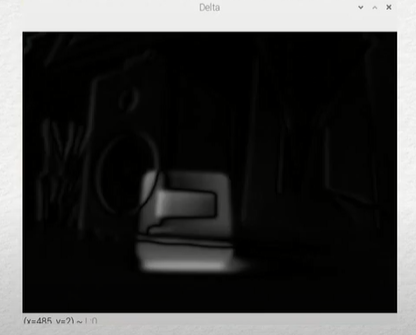
After that this image is converted into a binary black and white image which acts to finally segment the object in focus from the surroundings as the objects gets a white color and the environment is represented in a black shade.
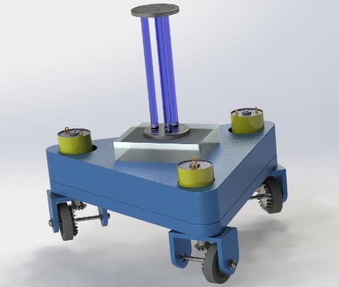
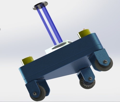
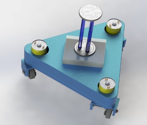
7. 3D Cad Model of Omnidirectional Robot
The 3D Cad Model of this omnidirectional vision capable mobile robot is carried out using solid works software and is rendered according to the physical hardware of the robot which is desired at the completion of this project. The cad design is shown as:
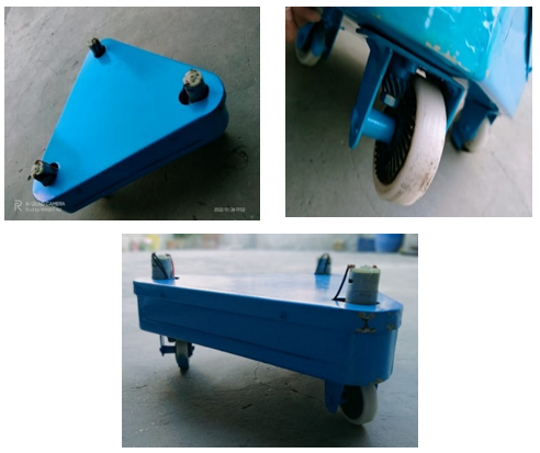
8. Mechanical Model
Using this 3D Cad model as a reference we have made an aluminum base frame with motors attached to it and also cut it according to the dimensions we used in our solid works’ design and also bought and used all the other components which include 3 Servo Motors, 3 DC gear motors, crown and pinion, Arduino Uno, Raspberry Pi 3B+ and Raspberry Pi camera module V2. Some of the images of the physical components and hardware are given in figure 21.
This entire design is made according to the calculations and theoretical derivations defined in the previous headings. The kinematic and dynamic analysis of our robot allows us to check as to what kind of components are required to make this robot and what kind of parameters do we need to make our robot a working success.
9. Conclusion
The main outcome of this paper is to explain the workings of our omnidirectional mobile robot with vision capabilities and explain how we can achieve this omnidirectional movement and how this robot will be used to avoid any and every object in the path of the robot. After learning everything, it can be concluded that the basic things required to achieve the omnidirectional motion of caster wheels are two kinds of motors, them being Servo and DC gear and control these motors using encoders and use pulleys to transfer the rotation torques and then use image processing to detect the objects in front of the robot and tell the motor to rotate or stop accordingly so that it would follow a dedicated path and use the Ultraviolet rays to disinfect the entire area in its pathway and make it safe for humans to enter and do their work in a germ-free and disinfected area.
Conflict of Interest
The authors declare no conflict of interest.
Acknowledgment
This paper is completed in Mechatronics Engineering department of the university of engineering and technology Lahore (Faisalabad Campus).
- H. Nacer, B. Mendil, “Motion analysis and control of three-wheeled omnidirectional mobile robot,” Journal of Control, Automation and Electrical Systems, vol. 30 no. 2, pp. 194-213, 2019.
- M.T. Riaz et al., “A wireless controlled intelligent healthcare system for diplegia patients”, Mathematical Biosciences and Engineering, 19(1): 456-472, 2022. doi: 10.3934/mbe.2022022
- H.A. Javaid et al., Classification of Hand Movements Using MYO Armband on an Embedded Platform. Electronics, 10, 1322, 2021. DOI: 10.3390/electronics10111322
- M. T. Riaz et al., “The Intelligent Transportation Systems with Advanced Technology of Sensor and Network,” 2021 International Conference on Computing, Electronic and Electrical Engineering (ICE Cube), 2021, pp. 1-6, doi: 10.1109/ICECube53880.2021.9628331.
- M. T. Riaz et al., “Design and Experimental Validation of a Small-Scale Prototype Active Aerostatic Thrust Bearing,” 2021 International Conference on Computing, Electronic and Electrical Engineering (ICE Cube), 2021, pp. 1-6, doi: 10.1109/ICECube53880.2021.9628270.
- M. A. Akbar, M. Shafiq, T. Kamal, M. T. Riaz, and M. K. Shad, “An empirical Study Investigation of Task Allocation Process Barriers in the Context of Offshore Software Development Outsourcing: An Organization Size Based Analysis,” International Journal of Computing and Digital Systems, 8(04), 343-350, 2019. DOI: http://dx.doi.org/10.12785/ijcds/080403
- M.A. Akbar et al., “Multicriteria Decision Making Taxonomy of Cloud-Based Global Software Development Motivators”, IEEE Access, 8, 185290-185310, 2020. DOI: 10.1109/ACCESS.2020.3030124
- M. A. Akbar et al., “Identification and Prioritization of Cloud Based Global Software Development Best Practices,” in IEEE Access, vol. 8, pp. 191242-191262, 2020, doi: 10.1109/ACCESS.2020.3031365.
- M. A. Akbar et al., “Requirements Change Management Challenges of Global Software Development: An Empirical Investigation,” in IEEE Access, vol. 8, pp. 203070-203085, 2020, doi: 10.1109/ACCESS.2020.3035829.
- M. A. Akbar et al., “AZ-Model of software requirements change management in global software development,” in 2018 International Conference on Computing, Electronic and Electrical Engineering (ICE Cube), 1–6, 2018. DOI: 10.1109/ICECUBE.2018.8610964
- A. Ahmed et al., “Modeling and Simulation of Office Desk Illumination Using ZEMAX,” in 2019 International Conference on Electrical, Communication, and Computer Engineering (ICECCE), 1–6, 2019. DOI: 10.1109/ICECCE47252.2019.8940756
- M. Taiyaba et al., “Secure V2X Environment using Blockchain Technology.” In Proceedings of the Evaluation and Assessment in Software Engineering, pp. 469-474. 2020. DOI: https://doi.org/10.1145/3383219.3383287
- M. Shafiq et al., “Towards successful global software development.” In Proceedings of the Evaluation and Assessment in Software Engineering, 445-450. 2020. DOI: https://doi.org/10.1145/3383219.3383283
- M. T. Riaz et al., “Investigation of Electrical Properties of Epoxy Resin Composite with the Surface Modification of SiO2 Nanoparticles,” 2021 International Conference on Computing, Electronic and Electrical Engineering (ICE Cube), 2021, pp. 1-5, doi: 10.1109/ICECube53880.2021.9628354.
- M. T. Riaz et al., “Wireless Model for High Voltage Direct Current Measurement using Hall Sensor,” 2021 International Bhurban Conference on Applied Sciences and Technologies (IBCAST), 2021, pp. 642-647, doi: 10.1109/IBCAST51254.2021.9393186.
- M. T. Riaz, M. M. Afzal, S. M. Aaqib and H. Ali, “Analysis and Evaluating the Effect of Harmonic Distortion Levels in Industry,” 2021 4th International Conference on Energy Conservation and Efficiency (ICECE), 2021, pp. 1-7, doi: 10.1109/ICECE51984.2021.9406283.
- M.T. Riaz et al., “Design of a Free Energy Generator using Gravity Wheel & Dynamo,” 2021 4th International Conference on Energy Conservation and Efficiency (ICECE), 2021, pp. 1-5, doi: 10.1109/ICECE51984.2021.9406299.
- M. T. Riaz et al., “Steady State Analysis of HVDC Transmission System Based on MATLAB/SIMULINK,” in 2019 International Conference on Electrical, Communication, and Computer Engineering (ICECCE), 1–6, 2019. DOI: 10.1109/ICECCE47252.2019.8940745
- M. T. Riaz et al., “Research on the Protection of Hybrid HVDC System,” in 2018 International Conference on Power Generation Systems and Renewable Energy Technologies (PGSRET), 1–6, 2018. DOI: 10.1109/PGSRET.2018.8686007
- M. T. Riaz et al., “Wireless Android Based Home Automation System,” Advances in Science, Technology and Engineering Systems Journal, 2(1), 234–239, 2017. DOI: 10.25046/aj020128
- H. A. Raza et al., “Analysis the effect of 500kv High-Voltage Power Transmission Line on the Output Efficiency of Solar-Panels,” in 2019 International Conference on Electrical, Communication, and Computer Engineering (ICECCE), 1–6, 2019. DOI: 10.1109/ICECCE47252.2019.8940803
- L. Hanwu et al., “Regularity of Current Dispersal in Different Kinds of Grounding Electrode,” in 2018 IEEE International Conference on High Voltage Engineering and Application (ICHVE), 1–4, 2018. DOI: 10.1109/ICHVE.2018.8642240
- M. Idrees et al., “Fuzzy Logic Based Calculation and Analysis of Health Index for Power Transformer Installed in Grid Stations,” in 2019 International Symposium on Recent Advances in Electrical Engineering (RAEE), 4, 1–6, 2019. DOI: 10.1109/RAEE.2019.8887016
- U. Farooq et al., “A Reliable Approach to Protect and Control of Wind Solar Hybrid DC Microgrids,” 2019 IEEE 3rd Conference on Energy Internet and Energy System Integration (EI2), Changsha, China, 348-353, 2019. doi: 10.1109/EI247390.2019.9062101.
- A. Waleed et al., “Study on Hybrid Wind-Solar System for Energy Saving Analysis in Energy Sector,” 2020 3rd International Conference on Computing, Mathematics and Engineering Technologies (iCoMET), Sukkur, Pakistan, 2020, pp. 1-6, doi: 10.1109/iCoMET48670.2020.9073901.
- M. R. Javed et al., “Protection Scheme Design for Star Connected PMSG Based Wind Farm against Line Faults,” 2020 3rd International Conference on Computing, Mathematics and Engineering Technologies (iCoMET), Sukkur, Pakistan, 1-6, 2020. doi: 10.1109/iCoMET48670.2020.9074139.
- A. Waleed et al., “Effectiveness and Comparison of Digital Substations Over Conventional Substations,” Adv. Sci. Technol. Eng. Syst. J., 4(4), 431–439, 2019. DOI: 10.25046/aj040452
- M. R. Javed et al., “A Comparative Study of Maximum Power Point Tracking Techniques for Solar Systems,” 2019 22nd International Multitopic Conference (INMIC), Islamabad, Pakistan, 1-6, 2019. doi: 10.1109/INMIC48123.2019.9022762.
- C. McGinn, R. Scott, N. Donnelly, K. Roberts. M. Bogue, C. Kiernan, M., Beckett, “Exploring the applicability of robot-assisted uv disinfection in radiology,” Frontiers in Robotics and AI, p. 193, 2021.
- S. Z. Hassan et al., “Intelligent Control of Wind-Assisted PHEVs Smart Charging Station,” Energies, vol. 12, no. 5, p. 909, 2019.
- Tătar, M. Olimpiu, C. Cirebea, D. Mândru, “Structures of the omnidirectional robots with swedish wheels. In Solid State Phenomena,” Trans Tech Publications Ltd, vol. 198, pp. 132-137, 2013.
- E. Schahawi, W. Zingg, M. Vos, H. Humphreys, L. Lopez-Cerero , A. Fueszl, E. Presterl, “Ultraviolet disinfection robots to improve hospital cleaning: Real promise or just a gimmick,” Antimicrobial Resistance & Infection Control, vol. 10 no. 1, pp. 1-3, 2021.
- J. Moreno, E. Clotet, R. Lupiañez, M. Tresanchez, D. Martínez, T. Pallejà, J. Palacín, “Design, implementation and validation of the three-wheel holonomic motion system of the assistant personal robot (APR),” Sensors, vol. 16 no. 10, pp. 1658, 2016.
- K. Miyashita, M. Wada, “Study on Self-Position Estimation and Control of Active Caster Type Omnidirectional Cart with Automatic/Manual Driving Modes,” 2020 IEEE/ASME International Conference on Advanced Intelligent Mechatronics (AIM). pp. 1798-1803. IEEE, 2020.
- E. Rubies, J. Palacín, “Design and FDM/FFF Implementation of a Compact Omnidirectional Wheel for a Mobile Robot and Assessment of ABS and PLA Printing Materials,” Multidisciplinary Digital Publishing Institute (MDPI), vol. 9, no. 2, p. 43, 2020.
- V. Mallikarjuna et al., “Design and fabrication of 180 degree wheel rotation vehicle,” International Journal of Latest Engineering Research and Applications, vol. 5, no. 11, 2018.
- A. Thankachan, A. Raveendran , S. Kumar, P. Arun Gawtham, P. Roy, A. Vishnu, “Design of 360 degree rotating car aided for parking,” International Journal of Latest Engineering Research and Applications (IJLERA), vol. 7, no. 4., 2018, doi:10.15680/IJIRSET.2018.0704112.
- Y. Fan, Y. Hu, L. Jiang, Q. Liu, L. Xiong, J. Pan, Q. Zhang, “Intelligent disinfection robots assist medical institutions in controlling environmental surface disinfection”. Medicentral.net, vol. 1, no. 1, pp. 19-23, 2021.
- A. Waleed et al., “Solar (PV) Water Irrigation System with Wireless Control,” in 2019 International Symposium on Recent Advances in Electrical Engineering (RAEE), 4, 1–4, 2019. DOI: 10.1109/RAEE.2019.8886970