Layer Based Firewall Application for Detection and Mitigation of Flooding Attack on SDN Network
(This article belongs to the Special Issue on Special Issue on Multidisciplinary Sciences and Advanced Technology (SI-MSAT 2022) and the Section Interdisciplinary Applications – Computer Science (IAC))
Export Citations
Cite
Gautam, Y. , Sato, K. and Gautam, B. P. (2022). Layer Based Firewall Application for Detection and Mitigation of Flooding Attack on SDN Network. Journal of Engineering Research and Sciences, 1(5), 88–101. https://doi.org/10.55708/js0105010
Yubaraj Gautam, Kazuhiko Sato and Bishnu Prasad Gautam. "Layer Based Firewall Application for Detection and Mitigation of Flooding Attack on SDN Network." Journal of Engineering Research and Sciences 1, no. 5 (May 2022): 88–101. https://doi.org/10.55708/js0105010
Y. Gautam, K. Sato and B.P. Gautam, "Layer Based Firewall Application for Detection and Mitigation of Flooding Attack on SDN Network," Journal of Engineering Research and Sciences, vol. 1, no. 5, pp. 88–101, May. 2022, doi: 10.55708/js0105010.
Software-Defined Networking (SDN) is an emerging Network technology that can augment the data plane with control plane by using programming technique. However, there are a numbers of security challenges which are required to address to achieve secured communication. Flooding attack is one of the most common threats on the internet for the last decades which is becoming the challenging issues in SDN networks too. To address these issues, we proposed a novel firewall application developed based on the multiple stages of packets filtering technique to provide flooding attack prevention system and layer-based packets detection system. In this research, we are using two main stages to detect the flooding attack and mitigate the flooding packets. The first stage is to identify the attacks and, the second stage is to identify the attacker’s information and act them based on layer-based packet header entity. The system contains two security entities to identify the flooding attacks, one is by measuring the packet size, and the other is by counting the packets flow. We used the details of packets flow to control over the flow and to identify the attacks being occurred or not. Along with, to identify the attacker’s information, we used layers (layer 2 to layer 4) based packet header entities by using multi-table architecture. The proposed solution was tested for different attack scenarios and successfully reduced the flow of volume-based bulk-size flooding attack and infinite packets flooding attack in SDN network.
1. Introduction
Traditional network refers to the network architecture based on old conventional way of networking which uses fixed and dedicated hardware devices to control the flow of network traffic. With the growth of the traffic or data in network, the network expansion takes place, and it may lead to inefficiencies in monitor or control over the network traffic. In order to meet the growing traffic demands, network expansion may require and much of the efforts go towards configuring switches and routers even for changes in a smaller segment of a local area network that may contain hundreds of nodes. Therefore, SDN network are desired that would control routing of flows in more efficient way. SDN separates the control plane from the data plane and single control plane can control all the network flows. There are different controllers available to use for the different purposes. Among them, widely used SDN controllers are Ryu, POX, ODL, and Floodlight etc. Specifically, the python-based Ryu controller is mostly used SDN controller for the research proposes [1]. Therefore, in this research we used the Ryu controller as an SDN controller.
In SDN network, the lack of efficient solution of packets flow control is the measure issue. To overcome those issues, we focused on the measurement of flow control based on counting the number of packets and their size. SDN has basically three layers which are infrastructure layer, control layer and application layer. Infrastructure layer contains the physical devices such as router, switch, hub etc. and control layer contains the controller which control all the network flows therefore, it is also called as brain of the SDN Network. And application layer contains the applications to operate the whole SDN network through controller. There are different controllers available to use for the different purposes. Among them, widely used SDN controllers are Ryu, POX, ODL, and Floodlight etc. Specifically, the python-based Ryu controller is mostly used SDN controller for the security-based research proposes. Therefore, in this research we used the Ryu controller as an SDN controller for SDN security research.
2. Literature Review
SDN system is an emerging network system for the general user and the network administrator also. It has centralized controlling system, faster and programmable features, which were lacking in traditional network system. However, it has high chances to be attacked by the attacker in various ways also. Research paper in [2] presents the evidence for three sides of the security pyramid that SDN possesses in its architecture. One side of the security pyramid consists of the advancement and other two sides consist of inherited vulnerability and its consequences on information security [2]. To address these attacks, we focused on the weak information security on SDN network architecture. For example, the attacker could easily spoof new flows in the controller and would forward specific types of traffic that should be rejected across the network. To minimize such kind of attack, we have developed a prototype application that can handle different types of flooding attacks in SDN network. Layered based security approaches are taken in many previous researches. Gautam and Shrestha [3] have presented a model for cloud computing security which are proposed in a layer based architecture. The authors propose different solutions and security policies to promote a common level of understanding between the users, business communities, and necessary security requirements for the Jyaguchi (it is a cloud system in which daily activity of the users and services are mined by considering time factor to analyze behavior of users) application. In SDN network, the vulnerability of network traffic in data centers under various kinds of attacks researches [4], [5] and [6] provide us some detail of SYN flood and DNS attack monitoring and analysis of network traffic by using TCP dump and Wireshark using Ryu controller [7], [8]. The vulnerability of network traffic in the data center under various kinds of attacks like DoS/DDoS attack is the biggest issue in traditional network system. To minimize this, there were some experiments and analysis to reduce such kinds of attacks by highlighting the major security threats based upon SYN floods followed by currently faced real working scenario by giving an example for DNS attack. It is also a fact that many organizations have not adequately secured there DNS servers. If the network system is centralized, then the analysis of network traffic will be easier to do. Providing a security policy for such a network system is our research objective. Previously, we have done some experiments on SDN system by developing the SDN hub application into different manners and checked the quality of service (QoS) based on its bandwidth, latency, and packet loss [9], [10]. The limitation of this research was that we had not considered the security issues in the SDN control plane. In the research of [11], the authors proposed an SDN design with star topology. Here, authors have argued that by using SDN multi-controller, it is effective to secure the network environment which is the better architecture for preserving or holding time than other works in the literature. In the SDN network system, DoS and DDoS attacks are the major issues like traditional network. The article in [12] provides the solution of the defending system for attack where the number of packets could either be high or low. The article of the effect of input-output buffering to minimize flow control blocking [13], [14] analyzes the different input-output buffering strategies which affects the flow control blocking in a SDN system. The network architecture of the SDN based 5G network system [15] with a centralized security controller that communicates with the SDN controller has been conducted previously. Related to the IoT security, authors in [16] have analyzed IoT security requirements, challenges, and their countermeasures via software defined security. Furthermore, they have highlighted some future research directions of SDN based IoT security technologies. They have mentioned that an adaptive, novel and worthy IoT security system is required to tackle the current security landscape which should be proactive in nature providing baseline security to end users, network, applications, data and devices. To overcome such issues, proactive switches are one of the solutions as we have implemented in this research. There are few other relevant researches in the SDN system security [17], [18]. The authors are mentioning different applications for working at different layers to block unwanted packets. Research papers of [19]-[21] have provided us some DoS or DDoS attacked based firewall application with load balancing.
3. Proposed Solution
We realized that there are some research gaps in SDN security if we analyze it on the perspective of layer-wise security or quantity-based flooding attack. In this research, we focused on layer-based security and flooding attack detection in the SDN (i.e. control plane) briefly to provide more protection by using multiple stages of filtering with multi table method. In order to address this issue, we have done some works in our previous researches [1], [22]. This is the continuity of our previous work in SDN to improve the security. Thus, we have found gap in the literature specifically in preventing flooding attacks based on bulk-size packets flooding and infinite packets flooding and, the flow control to provide SDN layer-base security. In this attack, an attacker can flood the unwanted packets to the network server to spoil the SDN network server. In such an attack, there is no satisfactory solution in SDN and conventional network systems.
Thus, in this research, we proposed an SDN network firewall application with having the features of layered based security architecture to detect the details of flows and flooding detection technique that can overcome the security issue of SDN network. We argue that by providing packet evaluation scheme based on security rules, security vulnerabilities of SDN network can be reduced sharply. Particularly, we would like to develop an application implemented by multiple filtering system to monitor the flow. We designed a firewall application applicable for the SDN control plane and conducted a number of experiments by flooding the packets. We defined specific rules and policies into the program by which the incoming packets are compared as per the firewall rules. If the flow matches with the defined rules, the packets will be allowed to flow to the targeted destination. Otherwise, firewall program declares those flows as a harmful flow and the system rejects them by minimizing the flooded packets and take actions to the attackers accordingly.
4. Research Methodology
In Figure 1, the system is categorized according to the SDN layers. The infrastructure layer represents the senders or receiver hosts and Open vSwitches It is the physical layer responsible for collecting the network statuses such as traffic statistic, network topology, network usage, etc. and send them to the control plane. Control plane is the mid-layer that connects the applications layer and infrastructure layer. This layer processes the instructions and requirements sent by the application layer and proceeds them to the network components. It also communicates back necessary information extracted from the networking devices to the application for it function optimally. There are already many controllers which were developed by different peoples for different purposes, but, for this research, we used Ryu controller as an SDN controller because, Ryu is mostly used controller for the research proposes.
4.1. Flow Table and Controller
To stablish the connection between infrastructure layer and control layer, we used OpenFlow protocol as a southbound API. We designed and developed a firewall application with multiple stages of filtering technique and applied this in SDN controller to filter the packets. By using this application, when Open vSwitch receives the packets from the source hosts, it will add the flow to the flow table on layer-based header entities and send the PacketIn message to the controller. The controller and switch perform three-way handshake by synchronizing the packets to stablish the connection between them. After
the completion of SYN process, the controller starts monitoring the packets based on packets size and total number of packets flow and send the PacketOut message to the destination if flows are normal. When system detects the flooding attack, it will minimize or drop those packets and take an action to the attackers based on their layer-based packets header entities. To perform these whole actions, we used three applications by running on the application layer. The rest API is used to stablish the connection between application layer and controller. ‘Rest_qos’ and ‘Rest_conf_switch’ is used to provide switch features to monitor the packets flow in Open vSwitch. And we used our developed ‘Firewall Application’ to identify the flooding attacks and an act to the attackers accordingly.
4.2. Packets Flow Scenario
We designed a network scenario of packets flow as shown in Figure 2. When the source generates the traffic and send them to the destination, the traffic passes through different Open vSwitches (depends on mininet network architecture) and controller with being monitored by the system on different stages. Mainly, we categorized the flow of packets into two parts, one is the flow of traffic in Open vSwitch (OVS) and the other is traffic in controller. The OVS stores the details of flows on layer-based packets header entities when it receives the traffic from source, and when filtration completes, it forwards the selected traffic to the destination. And controller monitors the traffic flow to control over them based on their flow size.
4.3. Algorithm of Flow Control
We presented here the algorithm of packets flow in table 1 to detect the flooding attack and act to them based on their flooded types. Where, all the flows have divided into the four parts. The first stage of application adds the flows on flow table based on their packet’s header entities to categorize the flow more specifically. Second stage of packets filtering measure the size of packets and act to them based on their size of packets by forwarding through different queues. Third stage of filtering counts the number of packets in every second and act them based on the defined rules on controller by sending the traffic through different queues. We can see in Figure 2 that the queues that counts the number of packets are Q4, Q5 and Q6. And fourth stage of filtering used to take an action to those packets flow which exceed the limits of numbers and size of packets as defined rules. In this stage, the flow will be stopped by using layer-based packets header entities.
Algorithm: Flow of traffic on proposed firewall application to detect flooding attack | ||
Results: Flooding attack detection and prevention by monitoring the flow of traffic | ||
Initialization; | ||
Check table-miss entry | ||
Check flow table | ||
First Stage: Add flow based on layer-based header | ||
If Flow exist Then | ||
Match with existing flow; | ||
Else | ||
Add new flows | ||
If Layer 2 packets Then | ||
Add flow with layer 2 packets header entities; | ||
Elif Layer 3 packets | ||
Add flow with layer 3 packets header; | ||
Elif Layer 4 packets | ||
Add flow with layer 4 packets header; | ||
PacketIn | ||
Check packets flow | ||
Second Stage: Measure size of flow | ||
If Size of packets flow is normal Then | ||
PacketOut | ||
Else | ||
If Exceeding first stage of packets size filtering Then | ||
Send packets to queue 1; | ||
If Exceeding second stage of packets size filtering Then | ||
Send packets to queue 2; | ||
If Exceeding third stage of packet size filtering Then | ||
Send packets to queue 3; | ||
Third Stage: Count No.of packets flow | ||
If Exceeding all the limits Then | ||
Send packets to Filter table; | ||
If Flow of packets are normal Then | ||
PacketOut | ||
Else | ||
If Exceeding first stage of packets count filtering Then | ||
Send packets to queue 4; | ||
If Exceeding second stage of packet count filtering Then | ||
Send packets to queue 5; | ||
If Exceeding third stage of packet count filtering Then | ||
Send packets to queue 6; | ||
Fourth Stage: Act based on packets header | ||
If Exceeding all the limits Then | ||
Send packets to Filter table; | ||
Filter table data send to action table | ||
If Layer 2 Then | ||
Act based on layer 2 action rules; | ||
Elif Layer 3 | ||
Act based on layer 3 action rules; | ||
Elif Layer 4 | ||
Act based on layer 4 action rules; | ||
End | ||
5. Experimental Scenario
5.1. Lab Setup
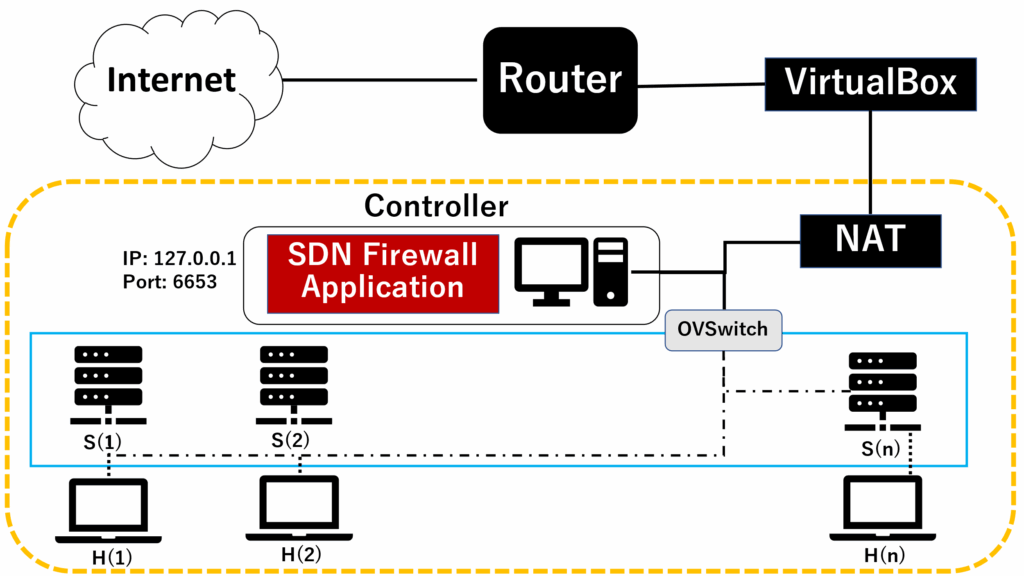
To conduct experiments, we created the laboratory as like Figure 3. We installed the virtual machine (Ubuntu 20.04) in the VirtualBox, and created the experimental scenario by installing mininet emulator on this machine.
5.2. Experimental Setup
5.2.1. Single Mininet Network
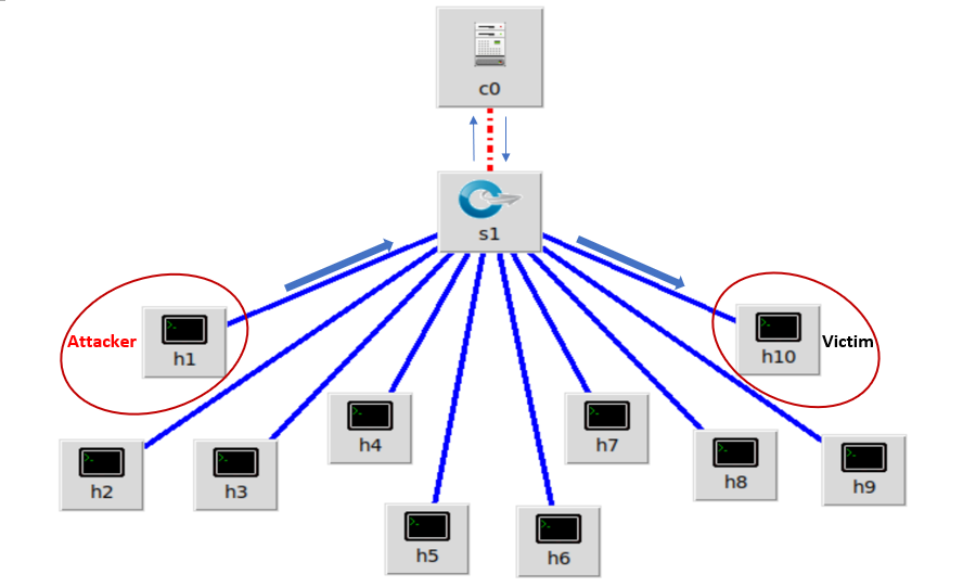
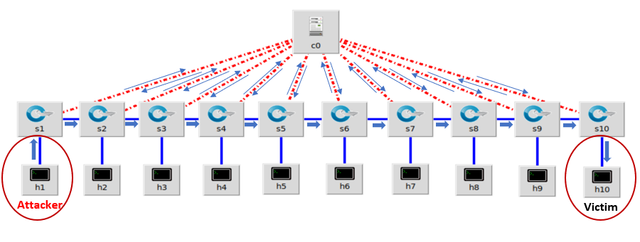
Figure 4 shows that the single mininet network topology which has single switch and multiple hosts connected to the OpenvSwitch. To create this network topology, we used one switch with ten mininet hosts (h1 to h10). All hosts are connected directly to the switch (s1) and the switch is connected with the Ryu controller remotely. In this network topology, h1 is used as an attacker and h10 is used as a victim machine. The flowing packets from attacker to the victim will flow through the switch s1.
5.2.2. Linear Mininet Network
To create linear mininet network topology, we used ten switches and ten hosts connected in a linear way as we can see in Figure 5. All switches are directly connected to the remote controller (c0) to get the instruction from controller. To conduct an experiment on linear mininet network topology, h1 is used as an attacker and h10 is used as a victim. When h1 sends packets to the victim, the packets pass through all the switches that exists in between source and destination. In our case, we used first host as sender and last host as the receiver, therefore the flooded packets will bypass all the existing switches in our designed system.
5.2.3. Tree Mininet network
Table 1: Experimental Plans
|
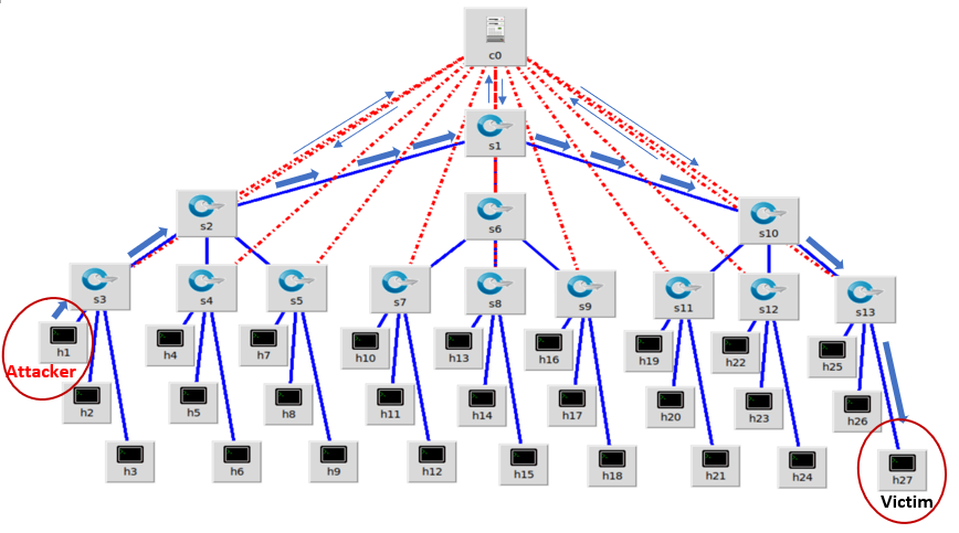
To create tree mininet network topology, we used three depth and three fanout as we can see in Figure 6. We created Open vSwitch from s1 to s13 and hosts from h1 to h27. In tree topology of SDN network, three depth means that the switches have three layers with the same number of fanouts. And, fanout means the number of children on each switch. In our tree network topology, s1 have three child switches (s2, s6 and s10) and further child switches have three more child switches, and all three child switches are connected with their parent switch. To conduct an experiment on this network topology, we used host s1 as an attacker host and s27 used as a victim host. As like the previous network scenarios, the flooded packets flow through the switches in between source and destination by identifying the best path to reach to the destination. In tree network topology, it forwards the packet flows to their parent switch by using the best path and reach to the targeted hosts.
5.3. Method of Data Collection
As shown in Figure 7 that OFPFlowStatsRequest are the flows between controller and switches. We accessed the size of packets flows by monitoring OFPFlowStatsRequest and saved as an CSV file in every 10 seconds. Similarly, to measure the flow of packets, we used the data of OFPPortStatsReply. We measured the flow of PortStatsReply that are directly connected to the attackers hosts and the victim hosts and compare with them to get the dropped packets. Moreover, we calculated the flow of increased packets and the packets that are permitted to enter the network as allowed packets.
To evaluate the system performance, mainly, we analyzed the flow of flooded packets and the flow of normal packets. We compared between those two different types of packets flows and evaluate the system based on how the controller takes an action to those individual packets flow. We used time series analysis to evaluate the system. Time series analysis is a statistical technique used to identify trends of flow over time. We used the sequence of data points which measure the same variable at different points in time.
5.4. Experimental Setup
As shown in table , we prepared two different kinds of attacks to collect the flow of data. One is by flooding the bulk-size packets to the victim and the other is by flooding the infinite packets. For Bulk-size flooding attack, we used UDP packets because we can set the size of UDP packets from low to the high range (8 to 65535 bytes). Specifically, to evaluate the packets flow, we sent two different types of flow. One is normal flow with smaller packets size, and another is flooded flow with higher packets size on same network architecture. Similarly, to evaluate the system performance with infinite packets flooding, we send normal traffic with less packets flow and flooded traffic with infinite packets in a
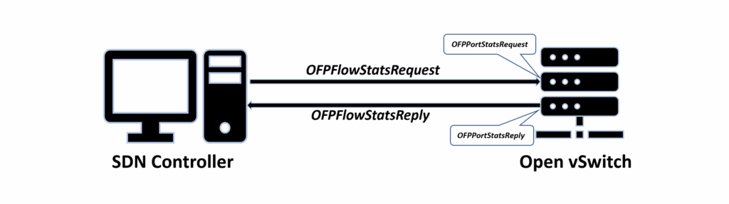
Table 2: Simulation Scenario & Parameters Settings
Configuration | Parameters | |
Mininet | Network Topologies 1. Single topology Topo=single, Hosts=10, IP=127.0.0.1, Port=6633 2. Linear topology Topo=linear, Hosts=10, IP=127.0.0.1, Port=6633 3. Tree topology Topo=tree, depth=3, fanout=3, IP=127.0.0.1, Port=6633 | |
Implemented Firewall Application | Queues (Q): Q0 = Normal Flow Q1 = Max Rate 9000000, Q2 = Max Rate 7000000, Q3 = Max Rate 5000000 Q4 = Max Rate 500000, Q5 = Max Rate 400000, Q6 = Max Rate 300000 If Byte count < 60000000 or Packets count < 200000 (Q0 active) | |
Bulk-size Flooding | Packets Flooding | |
If Byte count > 6000000 (Q1 active) If Byte count > 7000000 (Q2 active) If Byte count > 8000000 (Q3 active) If Byte count > 9000000 (Drop all) | If Packet count > 200000 (Q4 active) If Packet count > 300000 (Q5 active) If Packet count > 400000 (Q6 active) If Packet count > 500000 (Drop all) | |
Experiments | Tool: Iperf Measured Time: 90 to 95 sec | Tool: hping3 Measured Time: 90 to 95 sec |
second and evaluate the execution of SDN controller to those different packets flow. We collected the data of bulk-size flooding on every 5 seconds and 10 seconds to monitor the data of infinite packets flooding.
5.5. Simulation Scenario and Parameter Settings
To evaluate our application, we used the simulation parameters as shown in Table 2. We configured the Mininet emulator by using 3 types of topologies (i.e., Single, Linear and Tree). These topologies satisfy our experimental requirements of simple to complex networks thus we did not apply other network topologies such as star and mesh. Similarly, the parameters of firewall application are given such that the normal packets flow through Q0 when the size of packets flow is less than 6000000 bytes. When the size of packets crosses 6000000 bytes continuously, the system considers it as the flooded flow and forwards these flows to the different queues (Q1, Q2 and Q3) depending on their flooded packets size. Similarly, to detect the packets flooding, the rules have defined in the controller that if the total number of packets crosses the 200000, the system will recognize it as a flooded flow and forward the flows to the different queues (Q4, Q5 and Q6) based on their total number of packets as show in table 2. Moreover, we used iperf and hping3 to generate the flow of packets and monitor them up to 90/95 seconds to evaluate the system performance.
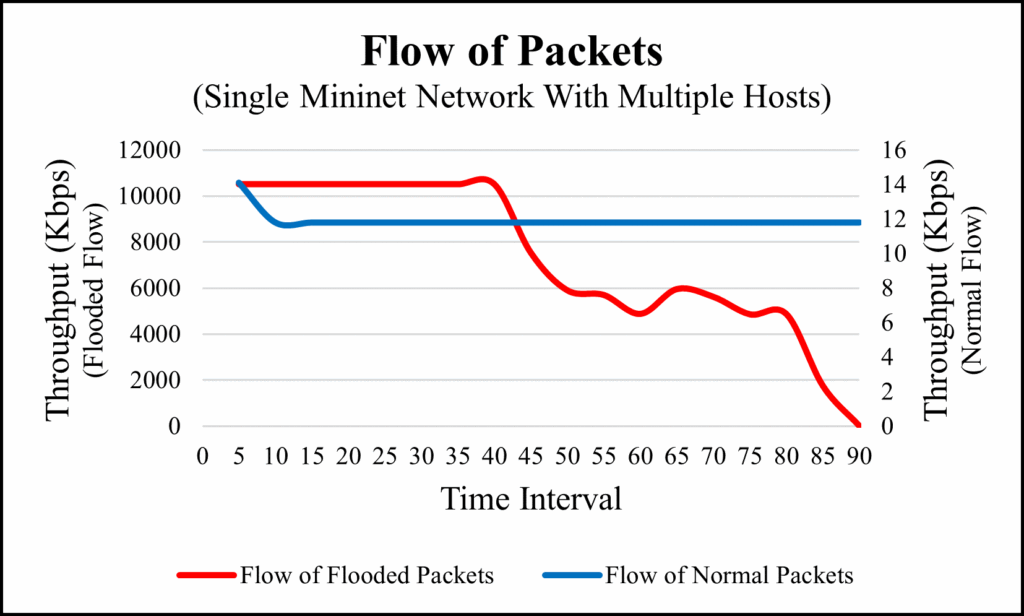
Table 3: Packets Size Detection in Single Topology
Normal Flow | Flooded Flow | ||||
Number of Flows | Time Interval | Packets_Size | Throughput (kbits/s) | Packets_Size | Throughput (kbits/s) |
1 | 5 | 7560 | 14.1 | 8799840 | 10500 |
2 | 10 | 15120 | 11.8 | 15563016 | 10500 |
3 | 15 | 22680 | 11.8 | 22326192 | 10500 |
4 | 20 | 30240 | 11.8 | 29098440 | 10500 |
5 | 25 | 36288 | 11.8 | 35194824 | 10500 |
6 | 30 | 43848 | 11.8 | 41953464 | 10500 |
7 | 35 | 51408 | 11.8 | 48719664 | 10500 |
8 | 40 | 58968 | 11.8 | 55488888 | 10500 |
9 | 45 | 66528 | 11.8 | 62242992 | 7520 |
10 | 50 | 74088 | 11.8 | 66348072 | 5890 |
11 | 55 | 81648 | 11.8 | 70214256 | 5690 |
12 | 60 | 89208 | 11.8 | 73859688 | 4870 |
13 | 65 | 96768 | 11.8 | 77001624 | 5950 |
14 | 70 | 104328 | 11.8 | 80988768 | 5610 |
15 | 75 | 111888 | 11.8 | 84333312 | 4850 |
16 | 80 | 119448 | 11.8 | 87461640 | 4860 |
17 | 85 | 127008 | 11.8 | 90588456 | 1740 |
18 | 90 | 134568 | 11.8 | 0 | 0 |
6. Experiments and results
The designed network scenarios are shown in figures 3-6 which have the several number of virtual hosts and switches to monitor the different packet flows. We set up three different network scenarios (i.e., figure 4, 5 and 6) to analyze the SDN network packets flow. To investigate the performance of firewall application, we used four different types of packet flows in each network scenario. Among them, one is bulk-size packets flooding with the flow rate of 10Mbps and compare with the normal packets flow with the flow rate of 1Kbps. The other is by flooding the infinite packets in a second with ten thousand packets in a second and compare with the less packets flow. We sent ten packets in a second as a normal flow from source to destination.
6.1. Experiment 1: bulk-size flooding on Single mininet network
To conduct this experiment, we collected the total of 18 flows in every 5 seconds time interval. In normal flow, the throughput of the packet’s flows was constant but in flooded flow, the throughput of the packets flow was constantly decreasing as the flow of packets size goes increases as we can see in Table 3.
Figure 8 shows the flow of packets with their flow size and Figure 9 shows the flow of packets based on their throughput. In Figure 9, we can see that only the flow of flooded packets gets decreasing, whereas flow of normal packets remained constant.
6.2. Experiment 2: Infinite packets flooding on single mininet network
To conduct this experiment, we used the same network architecture as of experiment 1 with single second to get the normal traffic flow and then analyzed the response of firewall application over the different types of flows. We compared with those different flows and got the following results as shown in Table 4.
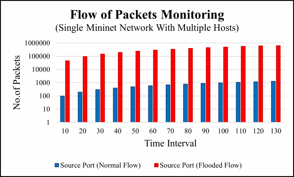
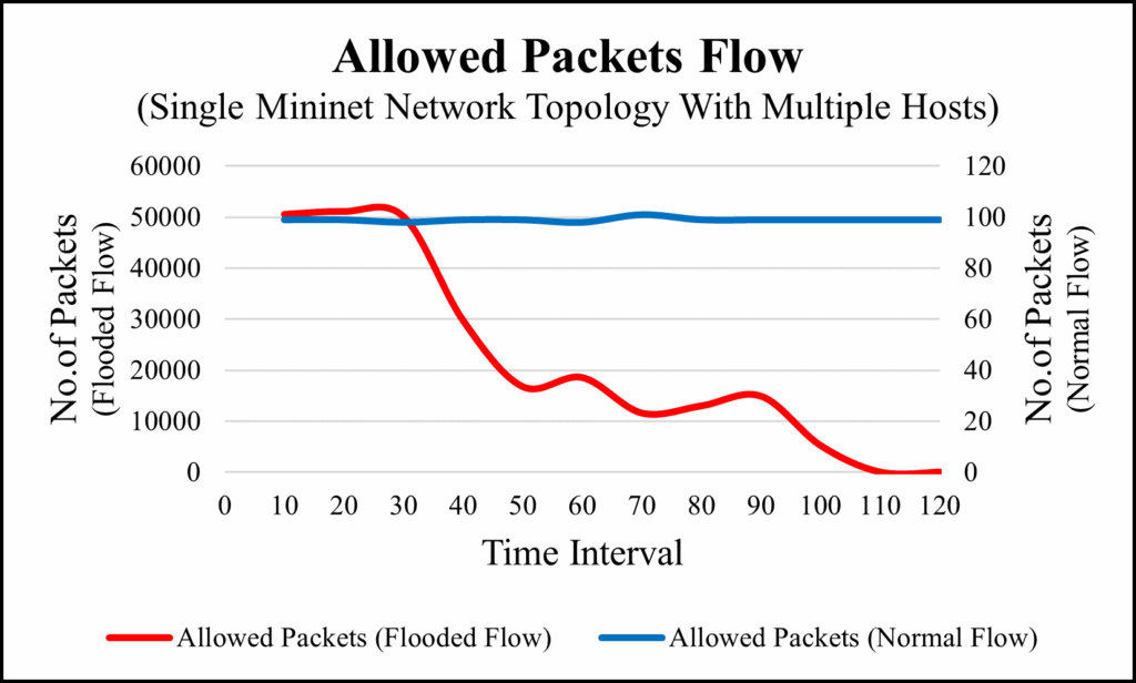
Table 4: Packets Flooding in Single Mininet Topology
Normal Flow | Flooded Flow | ||||||||||
Flows | Time Interval | Sender | Receiver | Dropped | Per Flow | Allowed Packets | Sender | Receiver | Dropped | Per Flow | Allowed Packets |
1 | 10 | 99 | 99 | 0 | 99 | 99 | 46209 | 46208 | 1 | 50581 | 50582 |
2 | 20 | 198 | 198 | 0 | 99 | 99 | 96790 | 96790 | 0 | 51158 | 51158 |
3 | 30 | 297 | 297 | 0 | 98 | 98 | 147948 | 147948 | 0 | 50129 | 50129 |
4 | 40 | 395 | 395 | 0 | 99 | 99 | 198077 | 198077 | 0 | 45616 | 29756 |
5 | 50 | 494 | 494 | 0 | 99 | 99 | 243693 | 227833 | 15860 | 50539 | 16756 |
6 | 60 | 593 | 593 | 0 | 98 | 98 | 294232 | 244589 | 49643 | 48618 | 18554 |
7 | 70 | 691 | 691 | 0 | 101 | 101 | 342850 | 263143 | 79707 | 53513 | 11582 |
8 | 80 | 792 | 792 | 0 | 99 | 99 | 396363 | 274725 | 121638 | 52977 | 12984 |
9 | 90 | 891 | 891 | 0 | 99 | 99 | 449340 | 287709 | 161631 | 52019 | 14910 |
10 | 100 | 990 | 990 | 0 | 99 | 99 | 501359 | 302619 | 198740 | 55931 | 5220 |
11 | 110 | 1089 | 1089 | 0 | 99 | 99 | 557290 | 307839 | 249451 | 59402 | 1 |
12 | 120 | 1188 | 1188 | 0 | 99 | 99 | 616692 | 307840 | 308852 | 21636 | 0 |
13 | 130 | 1287 | 1287 | 0 | 638328 | 307840 | 330488 | ||||
We collected the data of normal flow and flooded flow by using OFPflOFPFlowStats provided by Ryu controller API. We collected the data of 13 flow in every 10 seconds time interval. In normal flows, there are 0 dropped packets because the controller recognize that all the packets sent by source hosts are under the defined policy therefore, controller considers all the packets as a normal flow and forwards those packets to the destination. But on the other hand, in flooded flow, the controller detects that the incoming packets are exceeding the controller’s limits and recognizes as a flooding attack. As a result, the controller controls over those flooded packets by dropping them. To visualize the flow of packets, we prepared two graphs. Figure 10 is the graph of packets flow before going through our firewall application located in controller whereas Figure 11 is the graph of allowed packet flow after tested through our firewall rules targeted to the destination. The flow of normal packets is flowing constantly without any packets loss but if we observe the flow of flooded packets, we can see that the flow of allowed packets constantly decreasing and end up with 0 allowed packets. This shows the effectiveness of our firewall application.
6.3. Experiment 3: Bulk-size flooding on linear network
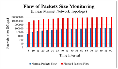
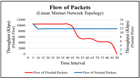
Table 5: Packets Size Detection in Linear Topology
Normal Flow | Flooded Flow | ||||
Number of Flows | Time Interval | Packets Size | Throughput (kbits/s) | packets Size | Throughput (kbits/s) |
1 | 5 | 3024 | 14.1 | 5821200 | 10500 |
2 | 10 | 10584 | 11.8 | 12593448 | 10500 |
3 | 15 | 18144 | 11.8 | 19361160 | 10500 |
4 | 20 | 25704 | 11.8 | 26124336 | 10500 |
5 | 25 | 33264 | 11.8 | 32210136 | 10500 |
6 | 30 | 40824 | 11.8 | 38976336 | 10500 |
7 | 35 | 48384 | 11.8 | 45733464 | 10500 |
8 | 40 | 55944 | 11.8 | 52489080 | 10500 |
9 | 45 | 63504 | 11.8 | 59253768 | 9530 |
10 | 50 | 71064 | 11.8 | 66016944 | 6290 |
11 | 55 | 78624 | 11.8 | 70409304 | 5290 |
12 | 60 | 86184 | 11.8 | 73994256 | 5450 |
13 | 65 | 93744 | 11.8 | 77440104 | 5230 |
14 | 70 | 101304 | 11.8 | 80876880 | 4440 |
15 | 75 | 108864 | 11.8 | 83876688 | 4250 |
16 | 80 | 116424 | 11.8 | 86660280 | 4290 |
17 | 85 | 123984 | 11.8 | 89445384 | 3410 |
18 | 90 | 131544 | 11.8 | 92157912 | 0 |
To conduct this experiment, we took h1 as a source and h10 as a destination host. H1 is directly connected to the switch s1 and h10 is directly connected to switch s10 as shown in Figure 5. To collect the data, we monitored the flow of packets passed by the controller and collect the size of flows in every five seconds time interval. We monitored the total of 18 flows and collected the data of normal and flooded flow as shown in Table 5. We monitored the flows up to 90 seconds and analyzed them based on throughput. We monitored the flow size of normal packets and flooded packets as shown in Table 5. To differentiate between normal and flooded packets, we graphed the flow of packets size before implementing the filtering system and packets flow after the packet’s filtration. Figure 12shows the flow of packets size monitored by the controller and Figure 13 shows the packets flow with their flow’s throughput.
6.4. Experiment 4: Infinite packets flooding on linear topology
To conduct this experiment, we used the network architecture of linear topology. To generate the traffic, we used h1 as an attacker and h10 as a victim host. We evaluated the system by collecting all the flowing data based on the controller’s response to the traffic flows. To collect the data, we monitored both ingress and egress ports of source and destination. Based on those two different flows, we collected the data of dropped packets, and allowed packets etc.
After the experiments, we got the following data as we can see in table 6. In normal flow, there are no dropped packets, because all the packets sent by the source reached to the destination with no issues. But, as we can see in flooded flow, it has the dropped packets right from the beginning. The allowed packets are getting lower and lower as the flooded packets getting bigger. Eventually, controller dropped the flooded packets completely. In Table 6 this is indicated with 0 packets. Figure 14 shows

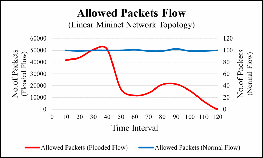
Table 6: Packets Flow in Linear Topology
Normal Flow | Flooded Flow | ||||||||||
Flows | Time Interval | Sender | Receiver | Dropped | Per Flow | Allowed | Sender | Receiver | Dropped | Per Flow | Allowed |
1 | 10 | 84 | 84 | 0 | 100 | 100 | 28371 | 28244 | 127 | 45215 | 41642 |
2 | 20 | 184 | 184 | 0 | 99 | 99 | 73586 | 69886 | 3700 | 43767 | 43764 |
3 | 30 | 283 | 283 | 0 | 100 | 100 | 117353 | 113650 | 3703 | 50515 | 50519 |
4 | 40 | 383 | 383 | 0 | 100 | 100 | 167868 | 164169 | 3699 | 50763 | 50760 |
5 | 50 | 483 | 483 | 0 | 100 | 100 | 218631 | 214929 | 3702 | 45523 | 17107 |
6 | 60 | 583 | 583 | 0 | 101 | 101 | 264154 | 232036 | 32118 | 52938 | 11589 |
7 | 70 | 684 | 684 | 0 | 99 | 99 | 317092 | 243625 | 73467 | 49801 | 13737 |
8 | 80 | 783 | 783 | 0 | 99 | 99 | 366893 | 257362 | 109531 | 32628 | 20930 |
9 | 90 | 882 | 882 | 0 | 102 | 102 | 399521 | 278292 | 121229 | 41537 | 21261 |
10 | 100 | 984 | 984 | 0 | 99 | 99 | 441058 | 299553 | 141505 | 47997 | 15673 |
11 | 110 | 1083 | 1083 | 0 | 99 | 99 | 489055 | 315226 | 173829 | 54705 | 6782 |
12 | 120 | 1182 | 1182 | 0 | 100 | 100 | 543760 | 322008 | 221752 | 60909 | 1 |
13 | 130 | 1282 | 1282 | 0 | 100 | 100 | 604669 | 322009 | 282660 | 20706 | 0 |
14 | 140 | 1382 | 1382 | 0 | 625375 | 322009 | 303366 | ||||
the flow of packets before the filtration and Figure 15 shows the allowed packets flow passes by the controller. As we can see in Figure 15 that allowed packet of normal flow remain constant in every time interval. But flooded flows have the dropped packets therefore, the allowed packets decreased and end up with 0 at the end.
6.5. Experiment 5: Bulk-size packets flooding on tree topology
To conduct the experiment on this network topology, h1 is used as source host and h27 is used as a destination host as shown in figure 6. In this topology, we got the total of 19 flows in 95 seconds. As like earlier experiments, normal packets have the constant flows with stable throughput whereas the flooded flow was decreasing constantly in their throughput as time went by. The Figure 16 and Figure 17 shows the flow of packets and the number of allowed packets respectively, and table 7 shows the details of collected data.
6.6. Experiment 6: Infinite packets flooding on tree topology
This is our last experiment to evaluate the performance of firewall application. To conduct this experiment, we sent 10 thousand packets per second as a flooded packet and 10 packets per second as a normal flow as like earlier experiments. The details of packets are shown in table 8. In normal flow, all packets sent by the source are delivered perfectly to the destination with 0
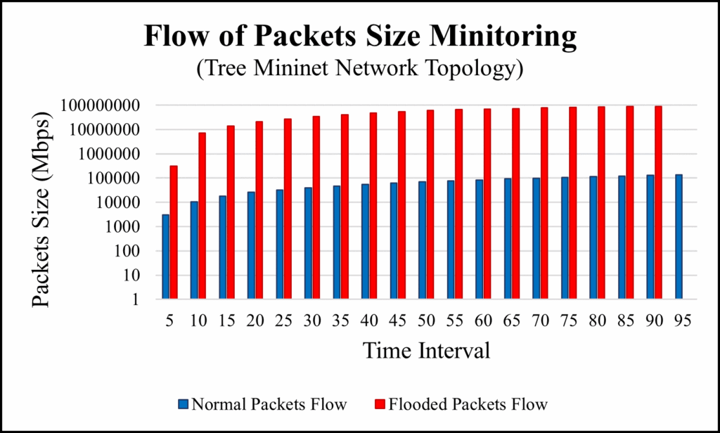
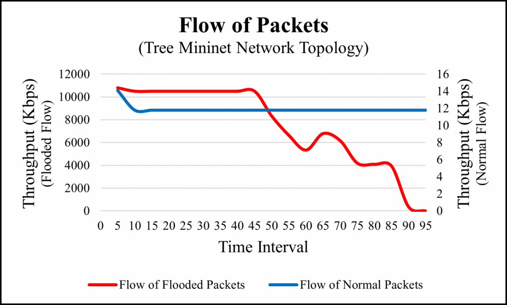
Table 7: Packets Size Detection in Tree Topology
Normal Flow | Flooded Flow | ||||
Number of Flows | Time Interval | Packets_Size | Throughput (kbits/s) | Packets_Size | Throughput (kbits/s) |
1 | 5 | 3024 | 14.1 | 317520 | 10800 |
2 | 10 | 10584 | 11.8 | 7080696 | 10500 |
3 | 15 | 18144 | 11.8 | 13852944 | 10500 |
4 | 20 | 25704 | 11.8 | 20623680 | 10500 |
5 | 25 | 31752 | 11.8 | 27392904 | 10500 |
6 | 30 | 39312 | 11.8 | 34156080 | 10500 |
7 | 35 | 46872 | 11.8 | 40916232 | 10500 |
8 | 40 | 54432 | 11.8 | 47027736 | 10500 |
9 | 45 | 61992 | 11.8 | 53822664 | 10500 |
10 | 50 | 69552 | 11.8 | 60584328 | 8320 |
11 | 55 | 77112 | 11.8 | 66101616 | 6630 |
12 | 60 | 84672 | 11.8 | 70401744 | 5340 |
13 | 65 | 92232 | 11.8 | 73844568 | 6790 |
14 | 70 | 99792 | 11.8 | 78179472 | 6160 |
15 | 75 | 107352 | 11.8 | 82175688 | 4190 |
16 | 80 | 114912 | 11.8 | 84968352 | 4090 |
17 | 85 | 122472 | 11.8 | 87609816 | 3930 |
18 | 90 | 130032 | 11.8 | 90107640 | 348 |
19 | 95 | 137592 | 11.8 | 0 | 0 |
packet loss. On the other hand, the flooded flow has dropped packets because, the controller is controlling over the flooded packets by dropping them based on the defined policy in controller. As a result, in flooded flow, the total number of packets per flow and allowed packets by the controller has differences. In Figure 18, we monitor the flow of packets before reaching to the controller and collect the data in every 10 seconds. Vertical-axis represents the number of packets and horizontal-axis represents the time interval in both Figures. In Figure 19, we can see that the flow of allowed packets getting reduced in flooded flow and flow of normal packets remained constant over all the period of time.
7. Conclusions and Future Works
In this study, we proposed a new security firewall application that can be deployed in an SDN. Our application was designed based on layer-based security filtering techniques to monitor the attackers and strengthen the network-wide security in an SDN. We presented security solutions based on measuring the flow of packets and their size and managed them based on different rule-based filtering tables, and briefly described the rules associated with the security solution. The defined rules control the limits of packets flow and flow size based on the system need. We have conducted two major experiments on four different network scenarios by flooding UDP and ICMP packets as a network flow. To analyze the performance of firewall application, we analyzed the flow pattern of normal packets flow and flooded packets flow. To evaluate the system, we monitored packets flow and packets drop ratio while reaching to the targeted destination. As a result, the controller detected the flow of packets based on layer-based packets headers entities and filtered those packets flow by counting the flow of packets and their flow size.
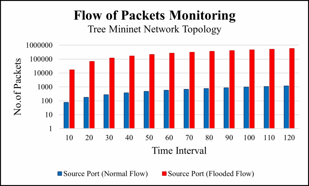
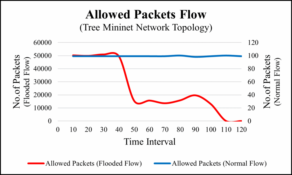
Table 8: Packets Flow in Tree Topology
Normal Flow | Flooded Flow | ||||||||||
Flows | Time Interval | Sender | Receiver | Dropped | Per Flow | Allowed | Sender | Receiver | Dropped | Per Flow | Allowed |
1 | 10 | 78 | 78 | 0 | 99 | 99 | 17023 | 17023 | 0 | 50215 | 50211 |
2 | 20 | 177 | 177 | 0 | 99 | 99 | 67238 | 67234 | 4 | 49827 | 49831 |
3 | 30 | 276 | 276 | 0 | 99 | 99 | 117065 | 117065 | 0 | 50882 | 50878 |
4 | 40 | 375 | 375 | 0 | 99 | 99 | 167947 | 167943 | 4 | 49392 | 49396 |
5 | 50 | 474 | 474 | 0 | 99 | 99 | 217339 | 217339 | 0 | 49608 | 15305 |
6 | 60 | 573 | 573 | 0 | 99 | 99 | 266947 | 232644 | 34303 | 48269 | 15655 |
7 | 70 | 672 | 672 | 0 | 99 | 99 | 315216 | 248299 | 66917 | 52365 | 13580 |
8 | 80 | 771 | 771 | 0 | 100 | 100 | 367581 | 261879 | 105702 | 46520 | 15819 |
9 | 90 | 871 | 871 | 0 | 98 | 98 | 414101 | 277698 | 136403 | 48565 | 19644 |
10 | 100 | 969 | 969 | 0 | 99 | 99 | 462666 | 297342 | 165324 | 51482 | 12981 |
11 | 110 | 1068 | 1068 | 0 | 100 | 100 | 514148 | 310323 | 203825 | 60450 | 9 |
12 | 120 | 1168 | 1168 | 0 | 99 | 99 | 574598 | 310332 | 264266 | 60457 | 0 |
13 | 130 | 1267 | 1267 | 0 | 635055 | 310332 | 324723 | ||||
Finally, we concluded that the proposed firewall application is successful to minimize the bulk-size packets flooding and infinite packets flooding.
The limitation of current implementation is that it used single controller as a master controller which has all of authorities to control over the network. It might have issues of controller failure or other security issues which would destroy whole SDN network. Therefore, in our future work, we will apply the redundant controller to address this issue with high performance computing resources. The technique of load balancing would be crucial in such kind of experiments; however, this task is remained for our future works.
Conflict of Interest
The authors declare no conflict of interest.
- Y. Gautam, K. Sato, B. P. Gautam and N. Shiratori, “Novel Firewall Application for Mitigating Flooding Attacks on an SDN Network,” 2021 International Conference on Networking and Network Applications (NaNA), 2021, pp. 449-455, doi: 10.1109/NaNA53684.2021.00084.
- Raktim Deb and Sudipta Roy, “A comprehensive survey of vulnerability and information security in SDN,” Computer Networks, vol.206, 2022, doi: 10.1016/j.comnet.2022.108802.
- B. P. Gautam, D. Shrestha, “A model for the development of Universal Browser for proper utilization of computer resources available in service cloud over secured environment,” Proc. of the International MultiConference of Engineers and Computer Scientists 2010 (IMECS), 2010.
- D. Pun, A. Batajoo, B. P. Gautam, “Vulnerability of Network Traffic in Data Centers under Various kinds of Attacks,” IPSJ SIG Technical Report, Vol.2015-ITS-62, 2015.
- D. Kim, P. T. Dinh, S. Noh, J. Yi and M. Park, “An Effective Defense Against SYN Flooding Attack in SDN,” 2019 International Conference on Information and Communication Technology Convergence (ICTC), 2019, pp. 369-371, doi: 10.1109/ICTC46691.2019.8939937.
- P. Kumar, M. Tripathi, A. Nehra, M. Conti and C. Lal, “SAFETY: Early Detection and Mitigation of TCP SYN Flood Utilizing Entropy in SDN,” in IEEE Transactions on Network and Service Management, vol. 15, no. 4, pp. 1545-1559, Dec. 2018, doi: 10.1109/TNSM.2018.2861741.
- S. Asadollahi, B. Goswami and M. Sameer, “Ryu controller’s scalability experiment on software defined networks,” 2018 IEEE International Conference on Current Trends in Advanced Computing (ICCTAC), 2018, pp. 1-5, doi: 10.1109/ICCTAC.2018.8370397.
- T. Hu, Z. Guo, P. Yi, T. Baker and J. Lan, “Multi-controller Based Software-Defined Networking: A Survey,” in IEEE Access, vol. 6, pp. 15980-15996, 2018, doi: 10.1109/ACCESS.2018.2814738.
- Y. Gautam, K. Sato, B. P. Gautam and N. Shiratori, “Novel Firewall Application for Mitigating Flooding Attacks on an SDN Network,” 2021 International Conference on Networking and Network Applications (NaNA), 2021, pp. 449-455, doi: 10.1109/NaNA53684.2021.00084.
- D. Li et al., “Research on QoS routing method based on NSGAII in SDN,” Journal of Physics: Conference Series, vol. 1656, no. 1, 2020, doi: 10.1088/1742-6596/1656/1/012027.
- I. H. Abdulqadder et al., “Validating User Flows to Protect Software Defined Network Environments,” Security and Communication Networks, 2018, doi: 10.1155/2018/1308678.
- W. H. Muragaa, K. Seman, M. F. Marhusin, “Simulating DDoS Attack in sdn Network Using POX Controller and Mininet Emulator,” Proc. of 134th The IRES International Conference, pp.39-41, 2018.
- M. I. Lali et al., “Effect of Input-Output ( IO ) Buffering to Minimize Flow Control Blocking in Software Defined Networking,” Mobile Information Systems, 53(3), pp.208-213, 2016.
- R. M. Thomas and D. James, “DDOS detection and denial using third party application in SDN,” 2017 International Conference on Energy, Communication, Data Analytics and Soft Computing (ICECDS), 2017, pp. 3892-3897, doi: 10.1109/ICECDS.2017.8390193.
- X. Liang and X. Qiu, “A software defined security architecture for SDN-based 5G network,” 2016 IEEE International Conference on Network Infrastructure and Digital Content (IC-NIDC), 2016, pp. 17-21, doi: 10.1109/ICNIDC.2016.7974528.
- W. Iqbal, H. Abbas, M. Daneshmand, B. Rauf and Y. A. Bangash, “An In-Depth Analysis of IoT Security Requirements, Challenges, and Their Countermeasures via Software-Defined Security,” in IEEE Internet of Things Journal, 7(10), pp. 10250-10276, 2020, doi: 10.1109/JIOT.2020.2997651.
- D. He, S. Chan and M. Guizani, “Securing software defined wireless networks,” in IEEE Communications Magazine, vol. 54, no. 1, pp. 20-25, 2016, doi: 10.1109/MCOM.2016.7378421.
- A. M. AbdelSalam, A. B. El-Sisi and V. Reddy K, “Mitigating ARP Spoofing Attacks in Software-Defined Networks,” 2015 25th International Conference on Computer Theory and Applications (ICCTA), 2015, pp. 126-131, doi: 10.1109/ICCTA37466.2015.9513433.
- S. Morzhov, I. Alekseev and M. Nikitinskiy, “Firewall application for Floodlight SDN controller,” 2016 International Siberian Conference on Control and Communications (SIBCON), 2016, pp. 1-5, doi: 10.1109/SIBCON.2016.7491821.
- S. Kaur, K. Kaur and V. Gupta, “Implementing openflow based distributed firewall,” 2016 International Conference on Information Technology (InCITe) – The Next Generation IT Summit on the Theme – Internet of Things: Connect your Worlds, 2016, pp. 172-175, doi: 10.1109/INCITE.2016.7857611.
- N. Zope, S. Pawar and Z. Saquib, “Firewall and load balancing as an application of SDN,” 2016 Conference on Advances in Signal Processing (CASP), 2016, pp. 354-359, doi: 10.1109/CASP.2016.7746195.
- Y. Gautam, B. P. Gautam and K. Sato, “Experimental Security Analysis of SDN Network by Using Packet Sniffing and Spoofing Technique on POX and Ryu Controller,” 2020 International Conference on Networking and Network Applications (NaNA), 2020, pp. 394-399, doi: 10.1109/NaNA51271.2020.00073.
No related articles were found.