Design and Analysis of Dual Acting Opposed Piston MR Damper
(This article belongs to the Section Mechanical Engineering (MEE))
Export Citations
Cite
Khan, M. A. (2022). Design and Analysis of Dual Acting Opposed Piston MR Damper. Journal of Engineering Research and Sciences, 1(5), 145–153. https://doi.org/10.55708/js0105015
Muhammad Aamish Khan. "Design and Analysis of Dual Acting Opposed Piston MR Damper." Journal of Engineering Research and Sciences 1, no. 5 (May 2022): 145–153. https://doi.org/10.55708/js0105015
M.A. Khan, "Design and Analysis of Dual Acting Opposed Piston MR Damper," Journal of Engineering Research and Sciences, vol. 1, no. 5, pp. 145–153, May. 2022, doi: 10.55708/js0105015.
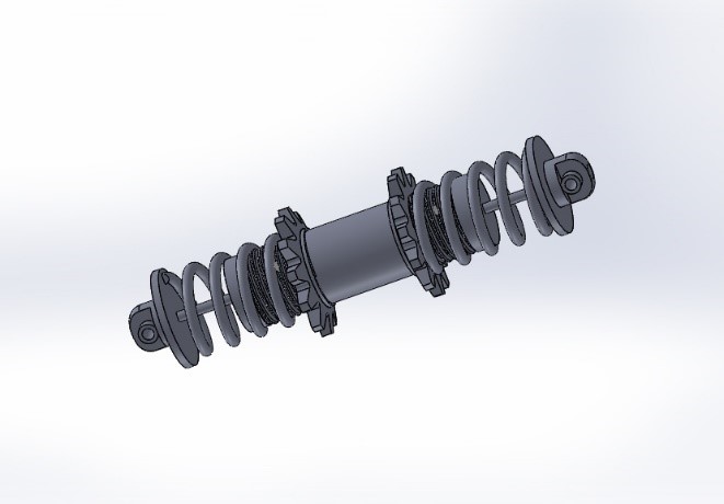
Magnetorheological dampers are dampers filled with magnetorheological fluid, which is controlled by a magnetic field, usually using an electromagnet. Viscosity of MR fluid changes with the application of magnetic field. In this way we can directly change the stiffness and performance of MR damper based on velocity of vehicle and topology of road, thus, providing the improved damping effect. This paper deals with improvement in MR damper design. The design proposed in this paper consists of two pistons with two linear generators in such a way that each piston couples with one linear generator. Both pistons work as opposed pistons, moving directly opposite to each other. This model utilizes six forces converging system to stability, leading to more compactness. Most of the forces including in this system vary with topology of road and velocity of car so leading to better robustness. In addition to this, model proposed is self-actuating and regenerative. Thus, resolves the issue of external power supply and harvests the vibrational force to develop electricity for its running. This model is self-dependent and doesn’t require on board electrical sensors and microprocessors, leading to more reliable MR damper design comprising of least components. There are multiple methods of actuation of MR damper which varies on the basis of structure and assembly, and type of generator used. Both linear and rotary generators can serve the purpose. In this paper linear actuation for this model is analyzed. This paper also deals with structural design and development of the model on the basis of certain parameters. Simulation and analysis of this model is then performed to assure the effectiveness of design. Solid works is being used for designing the structure of model and MATLAB for vibrational analysis. Simulink interface of MATLAB is used for electronic component analysis.
1. Introduction
A shock absorber is a mechanical device designed to absorb and damp shock impulses. It does this by converting kinetic energy of shock into another form of energy (typically heat) which is then dissipated. Dampers can be either active, passive or semi active. Passive dampers do not use any parameter to control damping coefficient in real time domain. Active dampers use road conditions and car speed as input and move damper piston up and down accordingly while semi active dampers vary damping coefficients accordingly. Shock absorbers can be of various shapes, they can be in leaf form, in torsion rod form or in hydraulic cylinder form.
MR dampers are type of damper that uses MR fluid as damping media whose viscosity can be varied with applied magnetic field thus changing damping coefficient. These dampers are very effective as they vary damping coefficient in real time according to surface of road. They generate magnetic field using electromagnets. So, by varying input current, damping coefficient can be changed. Input current is usually controlled by processing inputs like vertical speed and acceleration of chases of vehicle. MR dampers can be controlled by generators making then self-sustainable. Generator can be either linear or rotary with some changes in assembly. These regenerative MR dampers are cost effective as they don’t require an additional energy source. They provide better control and better performance. Regenerative MR dampers have higher damping capacities and are more compact in size. These dampers utilize emf (electromotive force) as an addition to other forces to converge system to stability. Among various types of regenerative magnetorheological dampers single-ended monotube regenerative MR (RMR) damper has maximum power generation capabilities [1]. MR damper finds its application from automobile industry to aerospace application. Civil structures also utilize MR dampers to prevent damage from seismic vibrations. Another application of emf force is regenerative braking system which utilizes generator for recovery of a part of kinetic energy during braking [2]. Generator generates electricity while producing electromotive force which creates braking effect. In addition to this, multiple efforts have been done, working on material science, to improve automotive, aerospace and aircraft, rail transport, and marine transport industry [3].
2. Literature review
The design MR damper in their paper considering non-Newtonian fluid and meeting device force capacity, size, and electrical power consumption [4]. They coupled non-Newtonian fluid with non-linear magnetic behavior of steel alloy to minimize power consumption. In the end, comparison between ER and MR damper is made based on power consumption.
It is developed a car model in ADAMS/Car for simulation purpose. A large bus is then tested to measure its dynamic response by the single-lane change test and the rapid stop test [5]. Simulation results were then compared to physical experiment in which several sensors were installed. The results from simulation were in good harmony with actual results. Then, they developed MR damper simulation using Magic Formula Model. Bump simulation of full car was performed. Vehicle with MR damper showed better response than vehicles with traditional passive damper.
The author studied the effect of iron particles-based MR fluid [6]. They prepared MR damper by adding iron particles in silicon oil. Then to reduce sedimentation, grease is used as stabilizer. Then sedimentation is measured under various concentrations of iron particles.
The author studied properties of MR fluid under application of magnetic field. In their paper they studied both MR fluid and FF [7]. MR fluid is modeled using Bingham model and FF is modeled using Newtonian model.
The author evaluated commercial MR damper for its application in semi-active suspension [8]. The experiments were carried out in damping force testing machine. MR damper RD-8040-1 by Lord Corporation, USA was used for testing at different values of current input. It was found that same damper can behave as under-damped system, critically damped system or overdamped system depending on the value of current supplied to it. It was also found that increase in MR damper load increases with current supplied which is studied and analyzed to develop a mathematical model of the MR damper under investigation.
The author worked on review paper which aims at a comprehensive review of development in structure and assembly of MR dampers [9]. This paper typically studies improvements of damping channels, magnetic circuit, coil number and distribution in recent years.
The author studied MR damper using SIMULINK environment in MATLAB for quarter vehicle model. Their first aim was to implement the correct control system for an active suspension system of a vehicle and a take closer look at the hydraulic cylinder and servo valve concept details and its closed-loop control system and the second aim was to gain both ride comfort and reliable road-holding by correctly tunning the PID parameters for an active suspension system to reduce the vehicle body displacement and acceleration [10]. Furthermore, the hydraulic pressure, hydraulic force, and total transmitted force to the vehicle body are compared for active and passive suspension systems. The simulation results showed that the car’s body displacement and acceleration have lower amplitude compared to the passive suspension case. Hence, active suspensions can provide the passengers more riding comfort and better roadholding while traveling over harsh street surfaces for the manufacturers [10].
The author studied various types of variable stiffness and variable damping techniques for semi-active MR dampers. To provide variable damping, MR damper is used and for achieving variable stiffness, the assembly of springs either in series or parallel is used [11]. Current is used for magnetization purpose which would in turn change the viscosity of fluid as required.
The author conducted a comprehensive study on control strategies and applications of MR dampers. They also discussed some properties of MR fluid and covered the operational modes of MR fluids. They analyzed dynamic model of MR damper and found it to be highly non-linear with its property of being time variant and hysteresis, and thus an accurate parametric model is challenging to be achieved. Considering the flexible mechanical properties and the faster response characteristics of an MR damper, a strategy combining the bionics and modern intelligent algorithm would be more suitable for controlling damping behavior of MR fluids as the approach is based on learning and ability to adapt [12].
3. Damper Components
Our proposed shock absorber consists of following parts:
- Two linear generators
- Two pistons
- Two springs
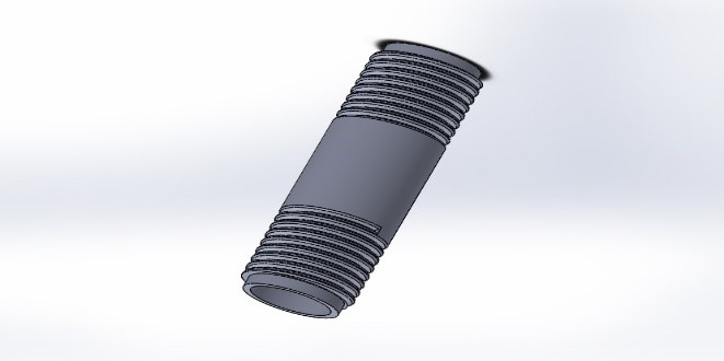
- Damper body
- Cover lid and follower rod
- Adjusting gear

4. Feasibility of proposed project
Feasibility here means the efficiency of proposed project, whether the proposed design is better than the previously used dampers or it is useless to perform these changes. To check this out transfer function of model is calculated and compared with standard damper.
To calculate transfer function, consider each part of suspension system independently.
4.1. Lower piston
Assume that xd – x1 is motion of lower piston relative to damper body.
The other forces applied to the piston are
- Spring force
- Viscous force
- Inertial force
- Magnetic levitation force
Force balance for piston
$$m\left(\frac{d^2 x_1}{dt^2}\right) = \text{F}(t) – k_1(x_1 – x_d) – c_1\left(\frac{dx_1}{dt} – \frac{dx_d}{dt}\right) – \frac{n^2 i^2 \mu a}{4(L – (x_0 + x_1))^2}$$
$$\quad \text{Solving } \frac{n^2 i^2 \mu a}{4(L – (x_0 + x_1))^2}$$
$$\quad \text{Suppose } \frac{n^2 i^2 \mu a}{4} = \text{B}$$
so \(\frac{B}{4} \left( L – (x_1 + x_2) \right)^{-2}\)can be solved as,
$$m\left( \frac{d^2 x_1}{dt^2} \right) = \mathrm{F}(t) – k_1(x_1 – x_d) – c_1\left( \frac{dx_1}{dt} – \frac{dx_d}{dt} \right) – \frac{B}{4L^2} – \frac{B}{2L^2} \left( \frac{x_1 + x_2}{L} \right) + \textit{neglecting higher powers}$$
4.2. Damper body
A part impact force will be transmitted by piston to damper body resulting in motion of damper x2-xd relative to upper piston. Therefore, force analysis of damper body is as under,
$$m_d \frac{d^2 x_d}{dt^2} = (k_1 – k_2)x_d + (c_1 – c_2)\left( \frac{dx_d}{dt} \right) – k_1 x_1 + k_2 x_2 – c_1\left( \frac{dx_1}{dt} \right) + c_2\left( \frac{dx_2}{dt} \right)$$
4.3. Upper piston
Damper body will also transmit a part of impact force to upper piston causing piston to move displacement x2. Resulting force balance is as under
$$m \left( \frac{d^2 x_2}{dt^2} \right) = k_2 x_2 – k_2 x_d + c_2 \left( \frac{dx_2}{dt} \right) – c_2 \left( \frac{dx_d}{dt} \right) + \frac{B}{4L^2} + \frac{B}{2L^2} \left( \frac{x_1 + x_2}{L} \right)$$
4.4. Using transfer function.
Using Laplace transform for all the above equations and solving them simultaneously we get,
$$X_2(s)(m_1 s^2 + 1 + c_1 s(s + 1) + 2B L^{-3}) + 2B L^{-3} + (-k_1 – c_1 s(s – 1))P = F(s)$$
where,
$$\left( \frac{m_2 s^2 + 1 + 2 c_2 s(s + 1) + 2B L^{-3} + k_2}{K + c_1 s(s + 1) – c_2 s(s + 1) – m_d s^2 + O^2} \right) = P$$
$$\quad (k_2 + c_2 s(s + 1)) = 0$$
$$\quad k_1 – k_2 = K$$
Since proposed model is about to be compared with damper of constant damping coefficient. So, above transfer function is obtained while considering constant damping coefficient i.e., MR fluid is not used yet. Moreover, back emf force is also neglected in this scenario for proper comparison.
Transfer function of mass m attached to spring with spring constant k and damper with damping coefficient c is,
$$\frac{X}{F} = \frac{1}{ms^2 + cs + k}$$
For comparison
B = 1 L = 1 c1 = c2 = 1 k1 = k2 = 1
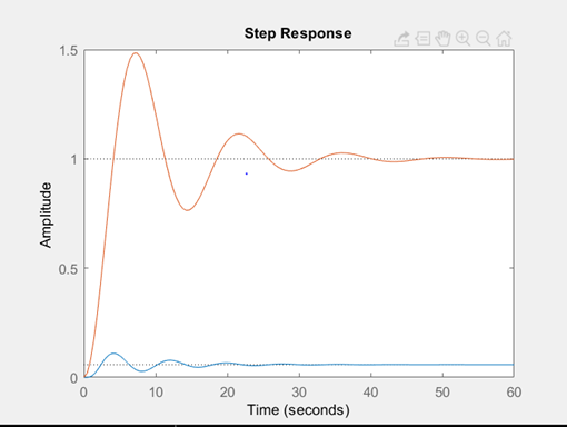
Blue line represents our proposed model
Red line represents traditional passive damper.
Note that damping ability has been improved manifolds.
5. Design of damper
To design damper, first thing we did is to apply boundary conditions related to riding comfort. Optimum conditions in this case are
$$x_1 = 2x_d$$
$$\quad \frac{dx_1}{dt} = 2\left(\frac{dx_d}{dt}\right)$$
$$\quad \frac{d^2x_1}{dt^2} = 2\left(\frac{d^2x_d}{dt^2}\right)$$
Therefore, damper body equation becomes
$$m_d \frac{d^2 x_d}{dt^2} + (c_1 + c_2) \left( \frac{dx_d}{dt} \right) + (k_1 + k_2)x_d = 0$$
Solving above equation we get
$$x_d = \frac{X}{K + m_d \omega_f^2} \sin(\omega_f t + \varphi)$$
5.1. Spring constant
Now we should calculate spring constants
Suppose we design for 40kg mass and assume static displacement to be 2in and damper body to be of 4kg.
For k1:
$$k_1 = \left( \frac{M + m}{x} \right) g = 29{,}302$$
For k2:
$$k_2 = \left( \frac{M}{x} \right) g = 25{,}480$$
5.2. Damping coefficient
Now, we need to decide the damping ratio value. We want to achieve robustness and wide range of control. Therefore, we should not limit damping ratio to a single value, rather it should vary with variation in conditions.
For proper functioning
$$x_d = \frac{Y}{2}$$
where Y is amplitude of jerk
Putting values and solving we get
$$\left( 3 – \left( \frac{M}{M + m_d} \right)^2 + 2\left( \frac{M}{M + m_d} \right) \right) k_1^2 + \left( 2\left( \frac{M}{M + m_d} \right) m_d w_f^2 – 2 m_d w_f^2 \right) k_1 + 4(c_1 w_f)^2 – m_d^2 w_f^4 = 0$$
Putting values, we get
$$70561199 – 1528.3 w_f^2 + 4(c_1 w_f)^2 – 4 w_f^4 = 0$$
$$c_1 = \frac{\sqrt{1528.3 w_f^2 + 4 w_f^4 – 70561199.5}}{w_f}$$
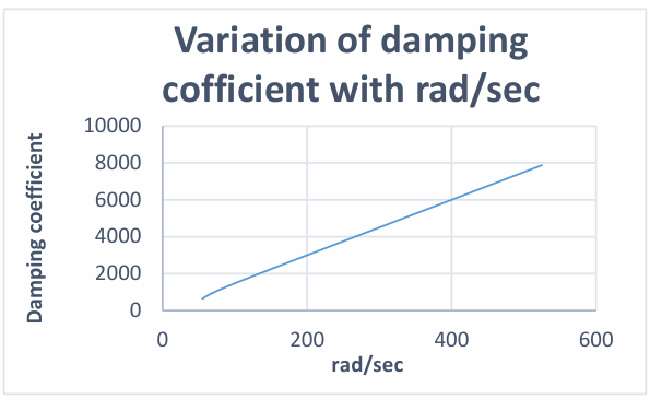
Varying value of angular velocity in above equation we get following graph of required damping coefficient.
5.3. Dimension of damper
The one-dimensional behavior of MR material undergoing simple shear is assumed to follow a Bingham constitutive model in which the applied shear stress is resisted by flux independent yield stress τy(B), and flux independent viscous stress. ηγ˙, [13]
$$\tau(B_g, \dot{\gamma}) = \tau_y(B_g) \, \mathrm{sgn}(\dot{\gamma}) + \eta \dot{\gamma}$$
Now by Bingham model
$$\tau_y = \tau_{y\infty} + 2(\tau_{y0} – \tau_{y\infty})\left(e^{-\alpha styB} – 0.5e^{-2\alpha styB}\right)$$
The pressure drop across the piston, ∆p, also has yielding and viscous components
$$\Delta p \approx 2.1 \frac{\tau_y}{t_g} + \Delta p_N$$
where the Newtonian viscous component, ∆pN, is approximated by.
$$\Delta p_N \approx \frac{12 Q \eta (2 N_s) L_p}{\pi (D_p + t_g) t_g^3}$$
where Ns is the number of spools of wire, Q is the volumetric flow rate, and Dp is the diameter of the piston.
The force generated in the device, F, is the pressure drop times the piston cross sectional area and can be expressed as,
$$F = \Delta p \pi \frac{(D_p + t_g)^2 – D_r^2}{4}$$
Here is the gap between piston and damper body and is the connecting for thickness. Assuming incompressibility, Q is related to the piston velocity, vp, by
$$Q = v_p \frac{\pi}{4} \left(D_p^2\right)$$
Thus, the device force may be obtained from the piston velocity, the device geometry, the MR fluid properties, and the magnetic flux density in the gap.
Since variation in damping coefficient and damping force is calculated so putting these values in above equations, we can calculate damper dimensions. The damper dimensions are as follow,
Piston diameter =1in
Piston thickness = 0.2in
Damper body inner diameter = 1.4in
Damper body outer diameter = 1.8in
Connecting rod of piston diameter = 0.2 in
Length of damper body = 8 in
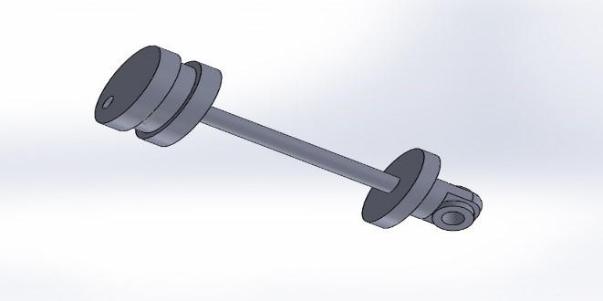
5.4. Buckling and its remedy
In this design there is a chance of buckling as damper body is suspended between upper piston and lower piston. Upper piston is attached to car body and lower piston to tyre.
To avoid bucking follower rod is used for pistons to follow. The cover lids and follower rod attached to them are shown below
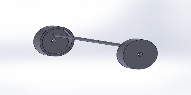
Pistons follow the follower rod and reduces chances of buckling. Multiple follow rods can be used depending upon design specifications. Above figure shows only single follower road.
5.5. Motion analysis of car body
Since upper piston is directly attached to car body. So, both will have same acceleration, velocity and displacement covered. The equation for displacement of upper piston in this case is as follow.
$$x = P \sqrt{S^2 – T^2}$$
where,
$$P = \sqrt{\left(\frac{\frac{BY}{2L^3} – \frac{k_2 X}{K + m_d w_f^2}}{}\right)^2 + \left(\frac{c_2 X w_f}{K + m_d w_f^2}\right)^2 – \frac{B}{4L^2}}$$
$$\quad S = \left( \frac{-M w_f^2 + k_2 + \frac{B}{2L^3}}{(-M w_f^2 + k_2 + \frac{B}{2L^3})^2 – (c_2 w_f)^2} \right)$$
$$\quad T = \left( \frac{-c_2 w_f}{(-M w_f^2 + k_2 + \frac{B}{2L^3})^2 – (c_2 w_f)^2} \right)$$
Solving the displacement of car body and displacement of damper body in real time domain with varying damping ratio and magnetic field throughout the jerk we obtain following curves.
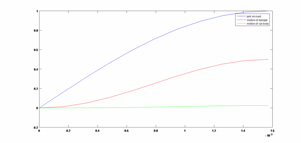
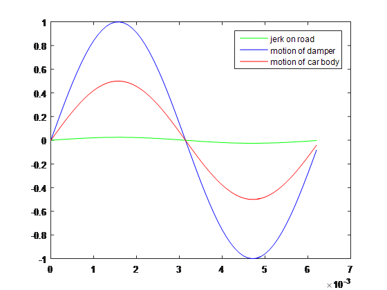
The responses show that very little motion takes place in car body and most of the jerk is absorbed by the damper.
The response is almost the same as long as magnetic field varies linearly with rpm and magnetic field produced follow the same trend as required.
5.6. Variation of magnetic field with angular velocity
Magnetic field increase with the increase in rpm and jerk velocity. For higher jerk velocity higher damping ratio and higher magnetic levitation force is required. Higher damping coefficient can be obtained by increasing viscosity. For MR fluid viscosity is the function of magnetic field and increase with the increase in magnetic field
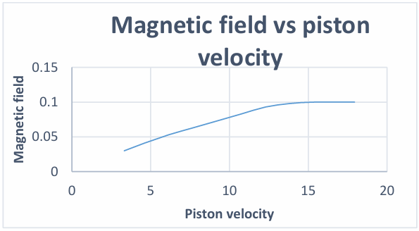
Trend shown in above graph shows that magnetic field does not increase linearly with piston velocity throughout the range. Rather it remains linear for some period and then saturation occurs.
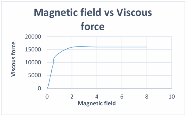
5.7. Variation of magnetic field with viscous force
Application of magnetic field make particles of MR fluid to arrange themselves resulting in increase in viscosity. In the beginning viscosity increase linearly with the increase in magnetic field. After that, the state comes when almost all the particles are arranged. Beyond this state further application of magnetic field would have no effect on increase in viscosity. Viscous forces increase with the increase in viscosity and piston velocity.
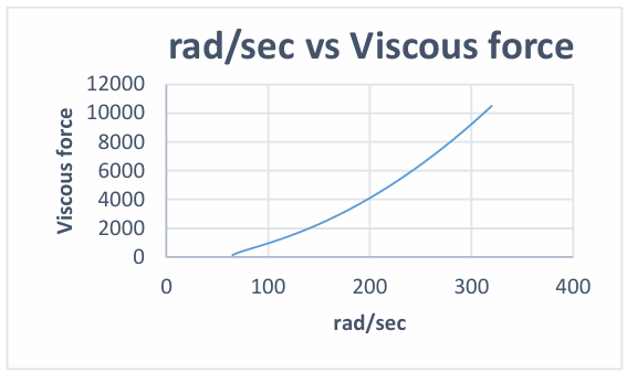
5.8. Variation of angular velocity with viscous force
Variation in viscous force required and angular velocity (rad/sec) can be seen in the following graph.
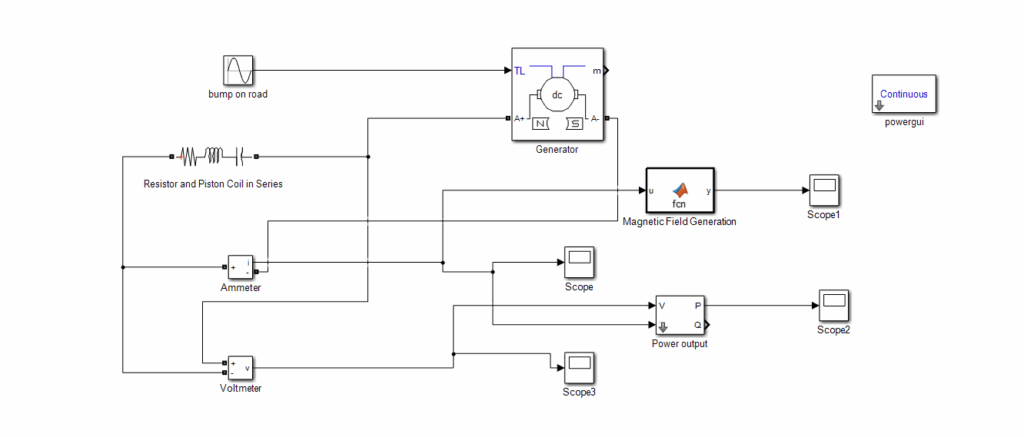
6. Mechanically actuating the damper
MR dampers can be actuated mechanically but it has its own pros and cons. The following benefits obtain by actuating the damper mechanically.
- More reliable – containing less electronic parts
- Provide back emf force to converge system to stability
This method has its own limitations also. Generators can actuate damper only within range where magnetic field varies linearly. Moreover, at high rpm values inductance also hinders the flow of current a lot. So, steps must be taken to reduce the inductance of system. Simulation is made using Simulink for mechanical actuation of MR damper. To decrease the inductive resistance within the circuit, linear generators with lower inductance are preferred over rotary generators. Since damper system works at higher rpm. So, lower the inductance in system better the system is.
Specifications for some main electrical components of this model are as under:
Table 1: Specifications of electrical components
DC linear generator | |
Internal resistance | 0.06 ohm |
Inductance | 0.003 H |
Back emf constant | 0.01 V/rpm |
Magnetic coils | |
Inductance | 0.0125 H |
Current, voltage and magnetic field variations for different rad/sec are as under
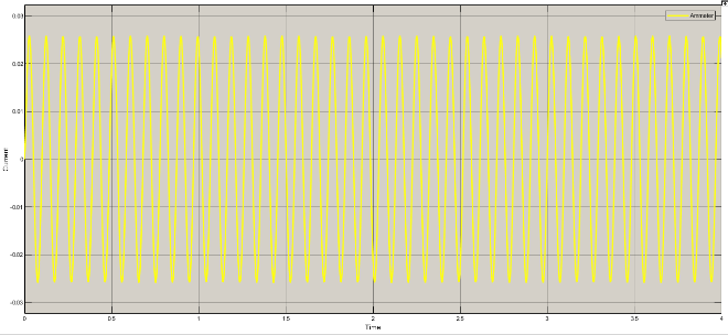
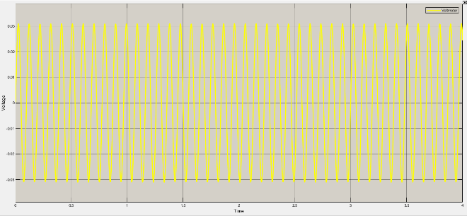
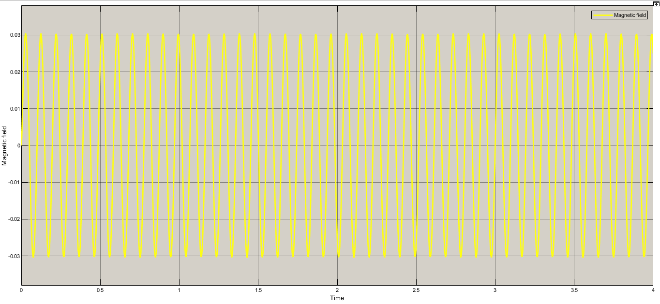
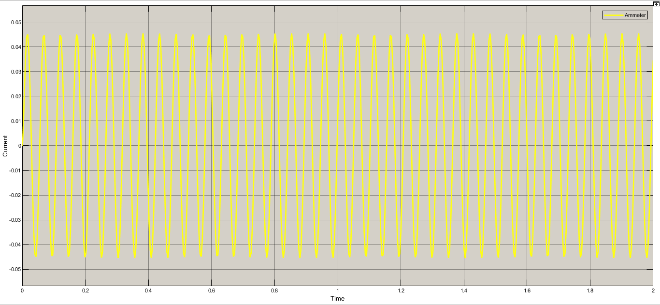
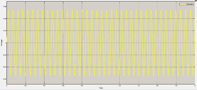
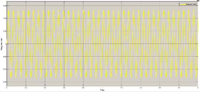
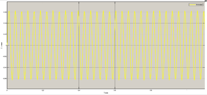
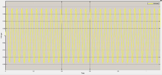
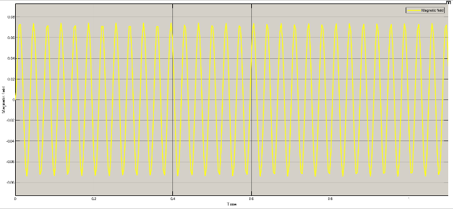
Table 2: Variation of current, voltage and magnetic field
Rad/sec | Piston velocity | current | voltage | Magnetic field |
65 | 3.33 | 0.025 | 0.03 | 0.03 |
90 | 4.62 | 0.035 | 0.042 | 0.041 |
120 | 6.15 | 0.045 | 0.052 | 0.053 |
150 | 7.69 | 0.054 | 0.062 | 0.063 |
180 | 9.23 | 0.061 | 0.071 | 0.073 |
210 | 10.76 | 0.072 | 0.081 | 0.083 |
240 | 12.3 | 0.078 | 0.093 | 0.093 |
270 | 13.85 | 0.08 | 0.099 | 0.098 |
300 | 15.38 | 0.087 | 0.11 | 0.1 |
350 | 17.94 | 0.094 | 0.12 | 0.11 |
7. Conclusion
MR dampers use MR fluid and vary the viscosity accordingly using magnetic field thus their performance is improved. The design we proposed uses two pistons and respective two linear generators with damper body. Pistons move opposite to each other thus dual action is achieved. Linear generators while producing electricity for damper generate electromotive force which improves the compactness of damper. The damping effect and stability is much improved using this design. This design eliminates the need of sensors and on-board micro-processors by actuating the suspension system mechanically. Linear generators have simple assembly and lower inductances than rotary ones. The graphs we obtained showed that generator with lower inductances would produce the desired fluctuation and variation of current as needed by design. This design is self-actuating and regenerative, so, requires no additional power supply and is thus a cheaper design with better control ability. This mechanical actuation limits the peak performance to a limited band of rpm values as generators tend to saturate at very high rpm values due to their inductances and thus don’t follow a linear curve. This design also faces a challenge of buckling, which is reduced by using follower roads.
Acknowledgment
I would like to express gratitude towards my parents for funding the research and towards my esteemed organization UET Taxila for providing me with insight and skills, and provided me with advanced labs to let me pursue my research. I am also grateful to respected reviewers for their insightful comments. I would like to thank my teachers also for helping me out in problems I faced in this research and providing me with ample knowledge to finally accomplish this research. In the end I would like to thank my colleagues for encouraging and supporting when things went tough.
- Sakib M. M., R. A., Md. Mahfujur Rahman, M. Abdul Aziz, “Recent developments of regenerative magnetorheological (RMR) damper,” Korea-Australia Rheology Journal, 2021, doi.org/10.1007/s13367-021-0017-x
- V. Sivamaran, A. Guru Pradeep, A. Manojkumar, A. Sujan, N. Balavenkatesh, and N. Vamsi, “Regenerative braking power system,” Manufacturing Technology Today, Vol. 20, No. 11-12, 2022.
- V. Sivamaran, S Azaruddin, K Sivaprasad, K Ravikumar, V Manoj Kumar, “A short review on applications of aluminium composites: automotive, aerospace and aircraft, rail transport, and marine transport industry,” Journal of Production and Industrial Engineering, Vol. 2, 2021,doi.org/10.26706/jpie.2.2.20211202.
- H. Gavin; J., Hoagg, and M., Dobossy, “Optimal design of MR dampers,” Japan Workshop on Smart Structure for Improved Siesmic Performance in Urban Region, Seattle, pp 225–236, 2001.
- Y. Kim, S. Choi, J. Lee, W. Yoo and J. Sohn, “Damper modeling for dynamic simulation of a large bus with MR damper,” International Journal of Automotive Technology, 2011, doi.org/10.1007/s12239-011-0061-5.
- S.E., Premalatha, R., Chokkalingam, and M., Mahendran “Magneto mechanical properties of iron based MR fluids,” American Journal of Polymer Science, pp. 50-55, 2012, doi: 10.5923/J.AJPS.20120204.01.
- M. Zubieta; S., Eceolaza; M.J., Elejabarrata; M.M., Bau-Ali, “Magnetorheological fluids: Characterization and modelling of magnetization,” Smart Materials and Structure , 2009, doi.org/10.1088/0964-1726/18/9/095019.
- Rangaraj M. D., Mohibb E. Hussain Jamadar, Hemantha K., Sharnappa J., S. C. Rajasekaran, and G. Amarnath, “Evaluation of a commercial MR damper for application in semi active,” SN Applied Sciences, 2019, doi.org/10.1007/s42452-019-1026-y.
- Xianju Y., Tianyu T., Hongtao L., Tianyu Q., and Huanli H, “A review on structural development of magnetorheological fluid damper,” Hindawi, 2019, doi.org/10.1155/2019/1498962.
- S. Babak, “A Review on PID control system simulation of the active suspension system of a quarter car model while hitting road bumps,” Journal of the Institution of Engineers (India): Series C, 2022, doi.org/10.1007/s40032-022-00821-z.
- Shivam S., and Ajaykumar U., “MR based semi-active suspension with variable stiffness and damping- an overview,” International Research Journal of Modernization in Engineering Technology and Science, vol. 3, 2021.
- Hongzhan Lv, Songsong Z., Qi Sun, Rui Chen, W. J. Zhang, “The dynamic models, control strategies and applications for magnetorheological damping systems: A systematic review,” Journal of Vibration Engineering & Technologies, 2020, doi.org/10.1007/s42417-020-00215-4.
- S.R. Hong, N.M. Wereley, Y.T. Choi, and S.B. Choi, “Analytical and experimental validation of a nondimensional Bingham model for mixed-mode magnetorheological dampers,” Journal of Sound and Vibration, Vol. 312, No. 399-417, 2008, doi 10.1016/j.jsv.2007.07.087.
No related articles were found.