Research on Feature Extraction Method of Fiber Bragg Grating Vibration Monitoring Based on FFT
(This article belongs to the Special Issue on Special Issue on Multidisciplinary Sciences and Advanced Technology (SI-MSAT 2022) and the Section Instruments and Instrumentation (INN))
Export Citations
Cite
Zhang, M. , Hua, Y. , Chen, C. , Chu, C. and Zhang, X. (2022). Research on Feature Extraction Method of Fiber Bragg Grating Vibration Monitoring Based on FFT. Journal of Engineering Research and Sciences, 1(7), 44–47. https://doi.org/10.55708/js0107007
Mengxing Zhang, Youming Hua, Chunbin Chen, Chenkun Chu and Xiuli Zhang. "Research on Feature Extraction Method of Fiber Bragg Grating Vibration Monitoring Based on FFT." Journal of Engineering Research and Sciences 1, no. 7 (July 2022): 44–47. https://doi.org/10.55708/js0107007
M. Zhang, Y. Hua, C. Chen, C. Chu and X. Zhang, "Research on Feature Extraction Method of Fiber Bragg Grating Vibration Monitoring Based on FFT," Journal of Engineering Research and Sciences, vol. 1, no. 7, pp. 44–47, Jul. 2022, doi: 10.55708/js0107007.
Optical fiber is used in various fields because of its advantages of large-capacity communication, long-distance transmission, low signal crosstalk, good confidentiality, anti-electromagnetic interference, good transmission quality, small size, light weight, and long life. In this paper, the latest research progress of optical fiber sensing technology and its application and development in the field of rotating parts are summarized, and the characteristics and working principles of optical fiber intelligent composite materials are introduced. Fast Fourier Transform (FFT) and Hilbert fringe spectra are then applied to frequency component analysis. Quantitative research is carried out on the variation of the frequency components in each frequency band of the vibration signal of the damaged and non-damaged rotating parts. The method can analyze the fault signal to achieve the purpose of accurately extracting the fault characteristics of the rolling bearing, which plays an important guiding role in the accurate diagnosis of the bearing fault.
1. Introduction
The acquisition and processing of fault signals is one of the main parts of fault diagnosis of rotating parts [1, 2]. When the rolling bearing fails, the frequency and amplitude of the fault signal will also change with time due to the influence of the type of fault, the degree of the fault and the change of the frequency of the rotating parts. Generally, the fault signal can be collected by fixing the fiber grating on the motor housing and collecting the vibration signal online [3-5]. In general, the fault diagnosis method of rotating parts is to obtain the actual frequency component of the signal through the processing and analysis of the fault signal, obtain the theoretical fault frequency of the signal according to precise calculation and analysis, and by comparing the two frequencies to further determine the type of rolling fault [6, 7]. However, when the rotating part fails, the analysis of the fault signal will find that the signal is often affected by the environment and the vibration of other parts of the rotating part, resulting in weak fault characteristics and easy to be overwhelmed by many noises [8]. Therefore, it has always been the research direction of domestic and foreign experts which method and means to use to analyze the fault problem of rotating parts, and effectively extract the fault features to realize the fault diagnosis of rotating parts.
Based on the above background analysis, this experiment aims to accurately extract the fault characteristics of the rotating parts, combined with the complex industrial environment and fault signal characteristics, comparing the signal perception and transmission efficiency of two types of acoustic emission sensors, and use the FFT frequency domain analysis method to analyze the fault signal to achieve the purpose of accurately extracting the fault characteristics of the rotating parts, it plays an important role in the accurate diagnosis of the fault of the rotating parts faults.
2. The mechanism of interaction between fiber Bragg gratings and acoustic emission waves
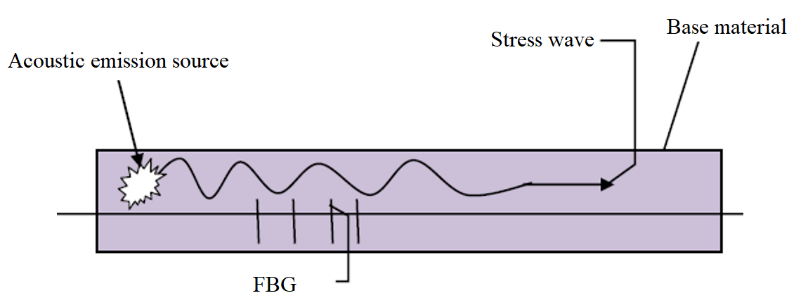
The fiber Bragg grating is closely attached to the surface of the object to be measured, as shown in Figure 1, the optical fiber material is used to make the sensitive structure of the rotating part, and the optical fiber directly embedded in the concrete structure. In this way, when the structure is deformed or otherwise defective due to changes in force and temperature, the gratings attached to the surface can deform, resulting in changes in the intensity, phase, wavelength and polarization of the light passing through the fiber. Based on the light variation information obtained, self-monitoring and diagnosis of stresses, deformations and cracks in rotating component structures can be determined [9, 10].
When the measured structure does not generate acoustic emission signals, the effective refractive index of the fiber Bragg grating is:
$$n_{\text{eff}}(z) = n_{\text{ef}0} – \Delta n \sin^2\left( \frac{\pi}{\Lambda_0} z \right), \, z \in [0, L] \tag{1}$$
where, the length of the grating region is the amount of refractive index change. The strain field model generated by the surface acoustic emission stress wave is,
$$\varepsilon(t) = \varepsilon_m \cos\left( \frac{2\pi}{\lambda_s} z – \omega_s t \right) \tag{2}$$
where ε𝑚 is the stress wave amplitude generated by the acoustic source in the material, 2π/λs is the number of acoustic emission waves in a single acoustic emission event, ωs is the angular frequency of the stress wave generated by the acoustic source, which can be expressed as ω𝑠 = 2π 𝑓s , where 𝑓s is the frequency of the acoustic emission wave, and λs is the wavelength of the stress wave generated by the acoustic source.
The variation of the central wavelength of the light emitted by the fiber grating is affected by both the period and the effective refractive index. Assuming that the fiber grating has a point z in the axial direction, it becomes z’ after modulation, and its relationship can be expressed by the following formula:
$$z’ = f(z,t) = z + \int_0^z \varepsilon(\xi) \, d\xi = z + \varepsilon_m \frac{\lambda_B}{2\pi} \sin\left( \frac{2\pi}{\lambda_s} z – \omega_s t \right) + \varepsilon_m \frac{\lambda_B}{2\pi} \sin(\omega_s t) \tag{3}$$
where, \(\int_0^z \varepsilon(\xi) \, d\xi\) is surface displacement due to acoustic emission waves.
Substitute 𝑧′ = 𝑓−1(𝑧,𝑡) into equation (1),The change in refractive index 𝑛′𝑒ff after modulation is calculated as,
$$n’_{\text{eff}}(z’,t) = n_{\text{ef}0} – \Delta n \sin^2\left( \frac{\pi}{\Lambda_0} f^{-1}(z’,t) \right) \tag{4}$$
The effective refractive index of fiber grating can be expressed as,
$$\Delta n’_{\text{eff}}(z’,t) = -\left( \frac{n_{\text{eff}0}^3}{2} \right) \cdot \left[ P_{12} – \nu (P_{11} + P_{12}) \right] \cdot \varepsilon_m \cos\left( \frac{2\pi}{\lambda_s} z’ – \omega_s t \right) \tag{5}$$
where pij is the elastic-optical coefficient of the fiber grating, and v is the Poisson’s ratio of the fiber grating. The modulated fiber Bragg grating wavelength becomes,
$$\lambda_B(t) = \lambda_{B0} + \Delta \lambda_0 \cos(\omega_s t) \tag{6}$$
Among them, Δλ0 is the change in the amplitude of the center wavelength when it is affected by the acoustic emission wave.
$$\Delta \lambda_0 = \lambda_{B0} \varepsilon_m \left\{ 1 – \left( \frac{n_{\text{eff}0}^2}{2} \right) \cdot \left[ P_{12} – \nu (P_{11} + P_{12}) \right] \right\} \tag{7}$$
Under the condition of 𝜆𝑠/𝐿 ≫ 1 , by detecting the change of the center wavelength of the reflected light of the fiber grating, the process of the continuous modulation of the fiber grating by the acoustic emission stress wave can be obtained.
Under the action of the acoustic emission signal of the fiber grating acoustic emission sensor, the center wavelength of the fiber grating in the fiber grating acoustic emission sensor changes, causing the reflected light to change. Through subsequent processing, the variation of the reflected light can be detected, and the corresponding acoustic emission signal can be obtained, so as to analyze the defects of the tested structure [11-14].
3. Grating experimental test device
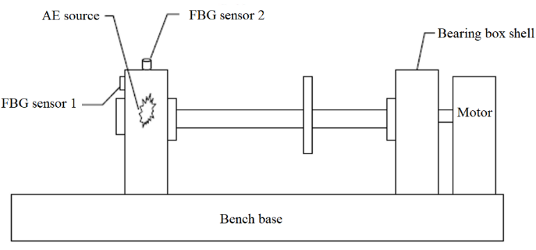
Nine simulated pitting faults were evenly distributed by Empirical Mode Decomposition (EMD) on the outer ring of the rolling bearing. The load condition was 5kN, and the speed conditions were 600r/min and 1200r/min. When the bearing is running, the acoustic emission signal emitted by the collision between the fault point and other components is an instantaneous pulse signal, which has the characteristics of wide signal spectrum and rich low-frequency signal content. Install the resonant acoustic emission sensor, bare fiber grating, and encapsulated fiber grating sensor on the experimental platform. The placement of the acoustic emission sensor in the experiment is shown in Figure 2. Connect and debug the instrument. The fiber grating static demodulator is connected to the computer through the network cable, the IP address is set, and the demodulation software ENLIGHT is debugged to set the data storage path; the previously processed faulty bearing is placed on the bearing frame, the sensor is connected, and the bare fiber grating, The substrate-type fiber grating sensor is connected to the two channels of the SM125 static demodulator through the jumper, and the data is collected.
4. Feature extraction of fiber grating vibration monitoring
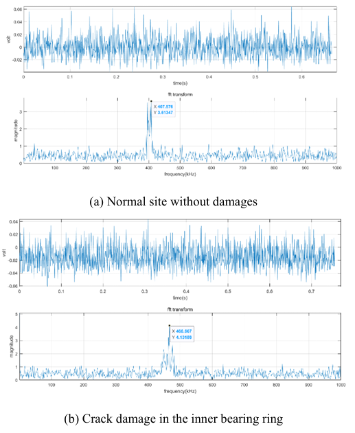
Figure. 3 is the frequency spectrum obtained by FFT transformation of the signal measured by the rotating part involved in the experiment under the condition of rotating speed of 1400 revolutions/min. Figure 3(a) is the shell vibration signal of the fiber grating before the outer ring is damaged, and Figure 3(b) is the vibration signal after the inner ring is damaged. It can be seen that there is a difference in the main vibration frequency. The main vibration frequency of the spectrum obtained by FFT transformation They are 408kHz and 467kHz respectively. After many tests, it can be seen that the fiber grating sensor can correctly detect the existence of defects regardless of whether the crack is located on the surface of the outer ring, or inside the inner ring and rolling body.
The FFT transformation is performed using MATLAB software, which visualizes scientific data and models nonlinear dynamic systems.
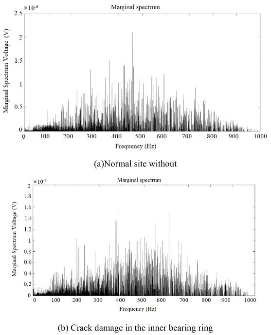
In order to quantitatively analyze the characteristics of elastic wave propagation during the rotational vibration of the rotating body, the marginal spectrum analysis of the fiber grating test signal is carried out. The traditional method is based on the fast Fourier transform (FFT) to obtain the frequency amplitude map. In this experiment, the Hilbert marginal spectrum is used to express the accumulation of the spectral amplitude at each frequency, which can more realistically reflect the frequency components. The amplitude has Additivity. Figure 4 shows the marginal spectral analysis results of the first-order IMF representing high-frequency components after different propagation distances. Under the condition of rotating speed of 1400 r/min, the Hilbert marginal spectral characteristic amplitudes of the vibration signals of the rotating parts before and after the destruction showed obvious differences. As shown in Figure. 4(a), the normal rotating parts show the characteristics of high relative change in amplitude in the low frequency range. While Figure. 4(b) shows the experimental rotating parts subjected to damage and damage treatment, the low frequency range below 200kHZ shows obvious characteristics of low relative change in amplitude, until the amplitude increases rapidly in the range of 200-300kHZ, showing high relative change in amplitude The characteristics of the FFT analysis were verified.
5. Conclusion
There are many new contents in the application of optical fiber sensing technology to the structure of rotating parts, and breakthroughs have been made in many key technologies, which have developed into a new branch with rich connotations, distinctive features and self-contained systems. In this paper, the vibration signal collected by the fiber grating is used to comprehensively analyze and study the frequency change of the vibration signal of the damaged and non-damaged rotating parts by FFT transformation, and it is concluded that it can be used for the health state monitoring of the rotating parts. The effectiveness of the FFT analysis method is verified by comparing the marginal spectral differences between the vibration signal processing results of the damaged and non-damaged rotating parts.
Conflict of Interest
The authors declare no conflict of interest.
Acknowledgment
This work was financially supported by the National Natural Science Foundation of China (11872191)
- Shen H , Li S, Gu D, et al. Bearing defect inspection based on machine vision[J]. Measurement, 2012, 45(4):719-733.
- Xiong Q, Zhang W, Xu Y, et al. Diagnosing axle box bearings’ fault using a refined phase difference correction method[J]. Journal of Mechanical Science and Technology, 2019, 33(1):95-108.
- Georgeson J D. Inspection of Roller Bearing Surfaces with Laser Doppler Vibrometry[J]. Journal of Manufacturing Science & Engineering, 1992, 114(1):123-125.
- Sheen Y T. A complex filter for vibration signal demodulation in bearing defect diagnosis[J]. Journal of Sound & Vibration, 2004, 276(1-2):105-119.
- Fu Z, Brown D J, Haynes B P . A new method of non-stationary signal analysis for control motor bearing fault diagnosis[C]// IEEE International Symposium on Intelligent Signal Processing. IEEE, 2003.
- Meng Z, Li S S. Rolling bearing fault diagnosis based on improved wavelet threshold de-noising method and HHT[J]. Journal of Vibration and Shock, 2013, 32(14):204-208+214.
- Guo J, Liu X, Li S, et al. Bearing Intelligent Fault Diagnosis Based on Wavelet Transform and Convolutional Neural Network[J]. Shock and Vibration, 2020, 2020(19):1-14.
- Singh G, Kumar R , Singh M , et al. Detection of crack initiation in the ball bearing using FFT analysis. 2017.
- Xuan G , Xiao-Peng Z, Ning L , et al. Research on Fiber Bragg Grating Acoustic Emission Technology Applied in Helicopter Bearing Detection[J]. Procedia Engineering, 2015, 99:1203-1212.
- Zhou X, Zhang H, Hao X , et al. Investigation on thermal behavior and temperature distribution of bearing inner and outer rings[J]. Tribology International, 2018, 130:289-298.
- L. Chen, Y.S. Choy, T.G. Wang, YK. Chiang, Fault detection of the wheel in wheel/rail system using kurtosis beamforming method, Struct. Health Monitor.19 (2) (2020) 495- 509.
- X Liu, D. Pei, G. Lodewijks, Z. Zhao, J. Mei, Acoustic signal-based fault detection on belt conveyor idlers using machine learning. Adv. Powder Technol. 31 (7)(2020) 2689- 2698.
- T. Tran, J. Lundgren, Drill fault diagnosis based on the scalogram and melspectrogram of sound signals using artificial intelligence, IEEE Access 8 (2020)203655- -203666.
- LAL Janssen, I. Lopez Arteaga, Data processing and augmentation of acoustic array signals for fault detection with machine learning, J. Sound Vib. 483(2020) 115483, https://doi.org/10.1016/j.jsv.2020.1 15483.