Hexagonal CSRR Based Broadband Monopole Antenna at UHF-Band

(This article belongs to the Special Issue on Special Issue on Multidisciplinary Sciences and Advanced Technology (SI-MSAT 2022) and the Section Electronic Engineering (EEE))
Export Citations
Cite
Yayan, S. M. and Aslan, A. F. (2022). Hexagonal CSRR Based Broadband Monopole Antenna at UHF-Band. Journal of Engineering Research and Sciences, 1(9), 1–7. https://doi.org/10.55708/js0109001
Suleyman Meliksah Yayan and Ali Furkan Aslan. "Hexagonal CSRR Based Broadband Monopole Antenna at UHF-Band." Journal of Engineering Research and Sciences 1, no. 9 (September 2022): 1–7. https://doi.org/10.55708/js0109001
S.M. Yayan and A.F. Aslan, "Hexagonal CSRR Based Broadband Monopole Antenna at UHF-Band," Journal of Engineering Research and Sciences, vol. 1, no. 9, pp. 1–7, Sep. 2022, doi: 10.55708/js0109001.
In this work, complementary split ring resonators (CSRR) based broadband monopole antenna is proposed. A variety of geometrical shapes are studied as a radiator to find out the radiator with the highest possible return loss bandwidth potential. It has been found that the semi-circularly shaped resonator has the widest VSWR<3 bandwidth. Therefore, a monopole antenna constructed by a semi-circularly shaped microstrip radiator which is excited with a 50-ohm microstrip line is proposed. It has been seen that a semi-circularly shaped microstrip radiator does not have adequate broadband performance in terms of VSWR<2 bandwidth. Therefore, CSRR structures that are shaped like hexagons are employed in order to enhance the VSWR<2 bandwidth of the proposed antenna. It has been seen that a single CSRR only influences a limited frequency range. In order to make the proposed monopole antenna operate within a much larger frequency bandwidth and achieve return loss enhancement along the whole frequency band, multiple equilateral hexagonal CSRRs are utilized. The ground plane of the monopole antenna is modified such that three CSRR structures having different dimensions are inserted behind the 50-ohm feeding line. The resulting manufactured monopole antenna operates from 320 MHz to 1100 MHz while having an average gain of 3.05 dBi gain. Moreover, the total efficiency of 94% is achieved along the operating frequency band.
1. Introduction
Nowadays, there is a continuously expanding demand for wireless and mobile broadcasting technologies. They rapidly became a vital part of our lives. These technologies utilize the UHF frequency band extensively. Aside from television broadcasting, the UHF frequency band is also used for marine and airborne navigation systems. All major global navigation satellite systems operate in the UHF band. What’s more, in addition to Wi-Fi and Bluetooth, there are a lot of wireless sound systems, and radio frequency identification (RFID) applications that operate at the UHF frequency band. Other than wireless communications, even the latest mobile communication networks such as 5G still operates in the UHF band. For long-range and low bandwidth applications especially in rural areas UHF frequency band provides a cost-effective alternative to operating at higher microwave frequency bands. UHF radio signals are also used for satellite communications. Especially CubeSat satellites which is a class of miniaturized satellites prefer the UHF frequency band due to its cost-effective and highly accessible nature. Tracking, telemetry data communication, and command subsystems of a satellite can all be managed successfully at UHF frequency bands. Most of the time monopole antennas are preferred to operate at the UHF frequency band. Monopole antennas are preferred extensively because of their omnidirectional radiation properties. In addition to having omnidirectional radiation, their broadband performance capability and ease of construction make them a very popular antenna type to be used in the UHF frequency band.
Several studies have been performed to enhance printed monopole antenna’s return loss bandwidth. A meander-shaped radiator that utilizes couplings between feeding lines is proposed in [1]. Another planar monopole antenna that is shaped like a Spirograph is mentioned in [2]. In order to enhance bandwidth, rf pin diodes are placed between the edges of the monopole antenna. In [3], wideband performance is achieved by employing an exponentially shaped patch radiator. The feeding of this radiator is accomplished by a capacitively coupled stripline structure. In another study, a fan-shaped radiator along with a trapezoidal ground plane is exploited in order to construct a half-sized unbalanced dipole antenna [4]. In [5], broadband circular polarization is acquired by inserting triangular notches into the rectangular resonator. 50-ohm coplanar line fed elliptical monopole antenna is proposed by [6]. In order to enhance bandwidth, a trapezoidal ground plane is utilized. Another study that employs a z-shaped monopole antenna is performed by [7]. In this study, a monopole antenna is constructed on a paper substrate while the antenna is printed on paper with silver and copper ink. Moreover, in the study performed by [8], a hexagonal CSRR structure is inserted into a hexagonal radiator in order to enhance the frequency bandwidth.
In this paper, the structure proposed in [9] is studied further. The frequency bandwidth of the equilateral hexagonal CSRR-based broadband monopole antenna that is proposed in [9] decreases by 130 MHz as a result of the insertion of the SMA connector into the model. Measurement results of the manufactured antenna indicate that the proposed antenna operates from 323 MHz to 1100 MHz after insertion of the SMA connector. Although the frequency bandwidth is affected negatively by the SMA connector, the average realized gain and percent total efficiency increase to 3.05 dBi and 94%consecutively after insertion of the SMA connector into the antenna model.
2. Design and Results
In Figure 1, the proposed antenna’s geometry is presented. The antenna is built on a material whose electrical properties are ϵr = 3.55 and tanδ = 0.0027 while the thickness of the substrate is chosen to be 0.81mm. The proposed antenna comprises of patch radiator that is semi-circularly shaped. Feeding of the patch radiator is realized by a 50-ohm transmission line. The ground plane of the proposed monopole antenna is modified such that three different CSRR structures that are hexagonally equilateral, are inserted onto it. The proposed antenna’s geometry is shown in Figure 1 while the proposed antenna’s dimensions are depicted in Table 1.
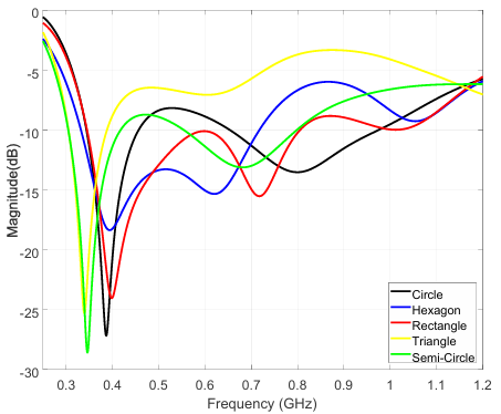
The initial design goal was to design a monopole antenna that has a 50-ohm feed line and fits within 300 mm of height. The operating frequency band is chosen to be 300 MHz to 1200 MHz for this design and the target VSWR is chosen as <3. Various microstrip resonators are studied in order to achieve the initial design goals. Circular, triangular, rectangular, and hexagonal shapes are chosen to be radiators of the monopole antenna and the structures are optimized to determine the best radiator. CST Microwave Studio environment is used for all the simulations.
In Figure 2, monopole antennas with different patch radiators’ optimized return loss results are given. It is seen from Figure 2 that the widest S11 bandwidth of -6 dB is achieved by the monopole antenna that has a semi-circular patch radiator. Although the antenna with a semi-circular radiator satisfies VSWR<3 within the frequency range of 300 MHz to 1200MHz, its frequency bandwidth where VSWR<2 i.e. frequency range where S11 is less than -10dB, is divided into two sub-frequency ranges. These frequency ranges are 300 MHz to 420 MHz and 560 MHz – 770 MHz.
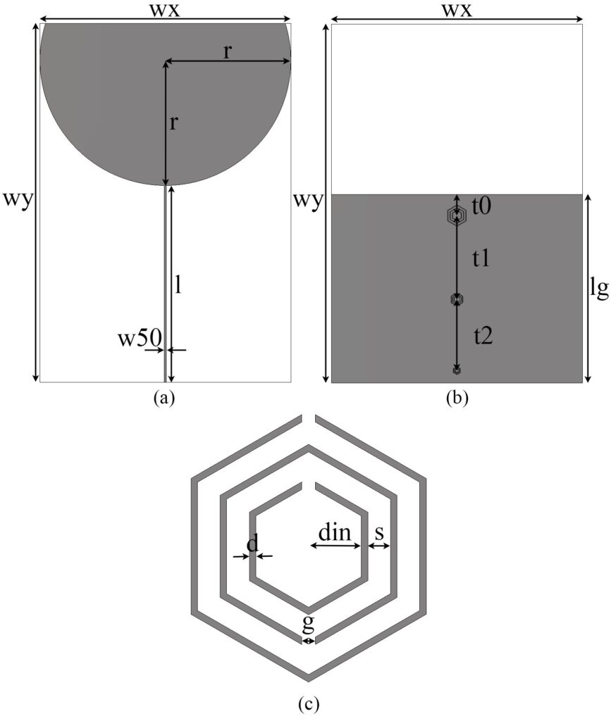
To be able to enhance the operating bandwidth of the monopole antenna that has a semi-circularly shaped radiator, CSRR structures are integrated into the ground plane of the monopole antenna. To achieve a broadband matching, operating frequency bandwidth is divided into three sections. For each frequency section, a different CSRR structure is used to enhance the matching. During the design process, three different equilateral hexagonal CSRR structures are utilized. For the sake of design simplicity, the largest CSRR is scaled down to obtain the other CSRR structures.
The scaling factors of the CSRR structures are inversely proportional to CSRR structures’ operating frequency. As the scaling factor reduces, the frequency of operation that a CSRR structure operates increases. Optimizations are performed by changing the dimensions of the largest CSRR and scale factors of the other CSRR structures. Optimal dimensions along with scale factors for the other CSRR structures are presented in Table 1.
Table 1: The proposed antenna’s dimensions.
Parameter | Value (mm) |
wx | 209.4 |
wy | 300 |
w50 | 1.8 |
r | 104.7 |
l | 164.5 |
lg | 157.71 |
din | 3.49 |
d | 0.43 |
s | 1.5 |
t0 | 17.7 |
t1 | 70 |
t0 | 59.4 |
g | 0.91 |
scalefactor1 | 0.62 |
scalefactor2 | 0.38 |
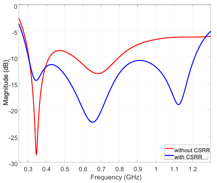
Figure 3 shows the proposed antenna’s return loss results with and without CSRR structures. It is seen from Figure 3 that after insertion of the CSRR structures, broad frequency bandwidth from 300 MHz to 1210 MHz has been achieved.
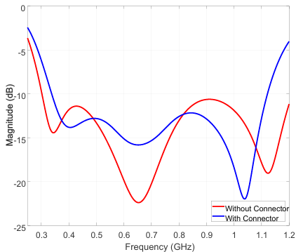
So as to acquire more realistic results, the SMA connector model that is used during measurements is added to the antenna model. In order to avoid any conduction problems, grounding vias has been inserted between the antenna’s ground plane and radiator surface where the center pin of the connector touches the 50-ohm transmission lines. In Figure 4, the proposed antenna’s return loss results without and with the SMA connector are provided. It is seen from Figure 4 that the insertion of the SMA connectors causes the frequency bandwidth of the monopole antenna to decrease by 130 MHz. Moreover, the lack of any unwanted ripples along the frequency band indicates that there is no conduction problem related to the integration of the SMA connector to the antenna model.
In Figure 5, the front view and back view of the electric field distribution are presented. Electric field density around the hexagonal CSRR structures in Figure 5 indicates that CSRR structures are effectively utilized for bandwidth enhancement. A closer look at the area where the SMA connector is located demonstrates no sign of conduction problems as it is also predicted by looking at Figure 4.
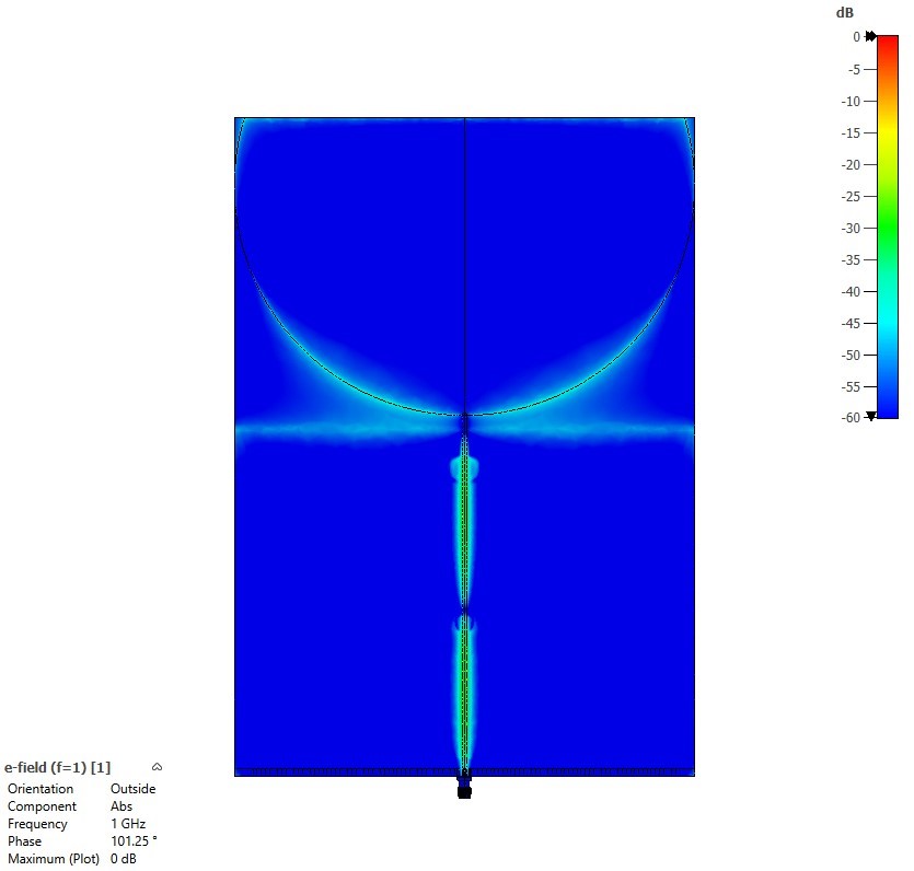
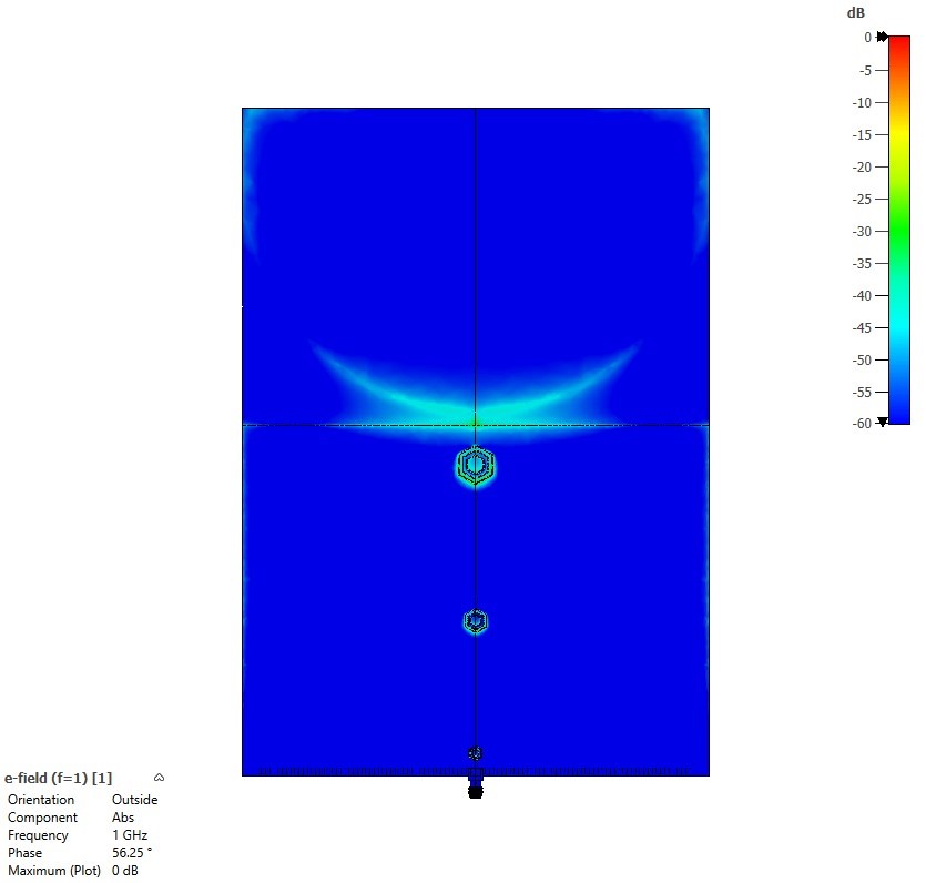
Figure 5: (a) Front view of the electric field distribution. (b) Back view of the electric field distribution.
In Figure 6 and Figure 7, 3D realized gain patterns of the proposed monopole antenna with SMA connector at 300 MHz, 500 MHz, 700 MHz, 900 MHz, 1000 MHz, and 1100 MHz are given.
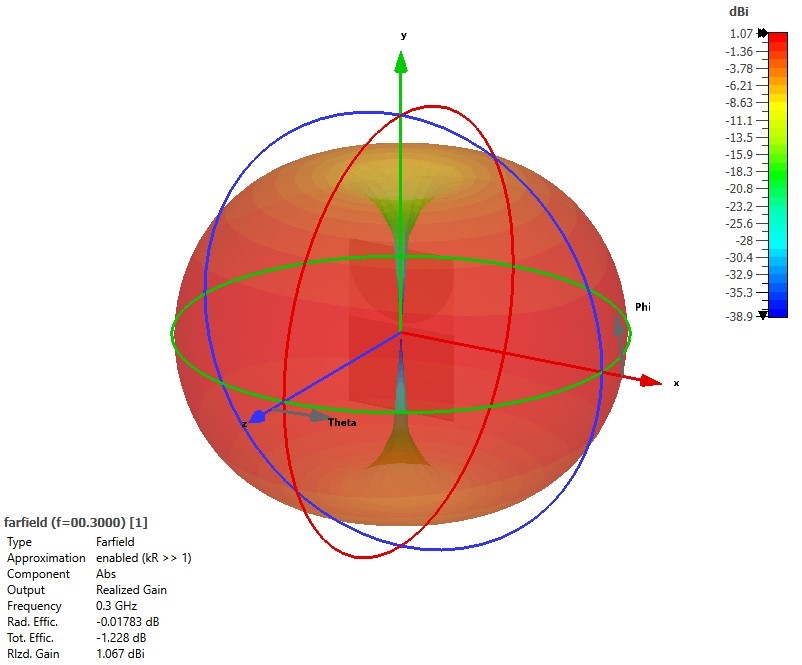
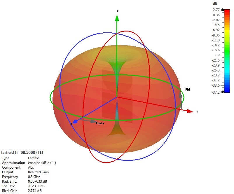
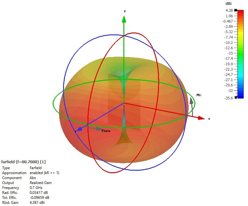
Figure 6: 3D realized gain patterns of the proposed monopole antenna with SMA connector at (a)300 MHz. (b)500 MHz. (c)700 MHz.
It is seen from Figure 6 that the proposed monopole antenna has an omnidirectional radiation characteristic. Especially up until 700 MHz, the proposed antenna indicates an ideal omnidirectional monopole antenna pattern. It is also seen from Figure 6 and Figure 7 that as the frequency of operation increases, the max gain of the antenna begins to shift towards the upper hemisphere of the 3D realized gain pattern. The tendency of the gain concentrating in the upper hemisphere also seems to affect the lower hemisphere where the null at the center of the lower hemisphere begins to disappear.
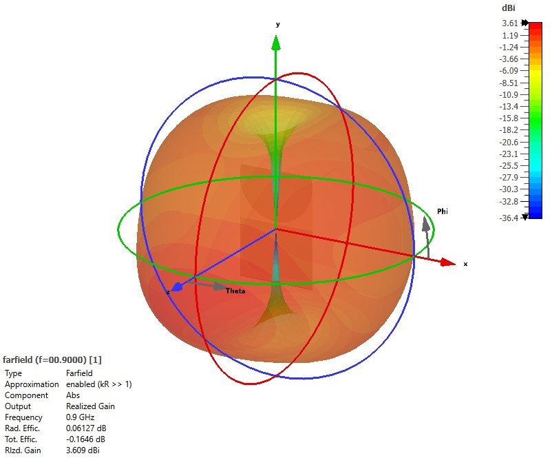
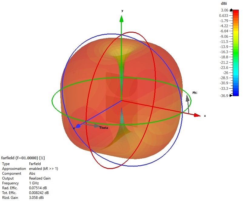
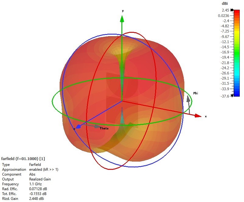
Figure 7: 3D realized gain patterns of the proposed monopole antenna with SMA connector at (a)900 MHz. (b)1000 MHz. (c) 1100 MHz.
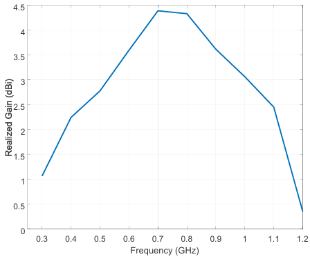
Figure 8 demonstrates the proposed antenna’s realized gain with the SMA connector, along the whole frequency band. Figure 8 shows that realized gain of the proposed antenna is around 1dB at the beginning and end of the frequency band. Max realized gain reaches up to 4.4 dBi at the center of the frequency band. It is also seen from Figure 8 that the antenna’s average realized gain is around 3.05 dBi.
In Figure 9, the proposed antenna’s total percentage efficiency with the SMA connector, along the whole frequency band, is provided. Figure 9 depicts that although the total percentage efficiency at the end and beginning of the frequency band is around 70%, it increases up to 97% at the middle of the frequency band. Moreover, Figure 9 also shows that an average of 94% total efficiency is accomplished within the whole frequency band.
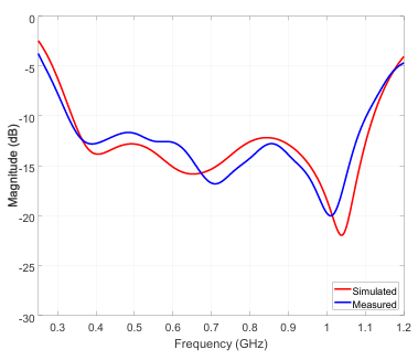
In Figure 10, the front and back view of the manufactured antenna is shown. The return loss of the manufactured monopole antenna is measured with a network analyzer. Figure 11 shows measured and simulated return loss results of the proposed antenna. It is seen from Figure 11 that simulated and measured results agree very well with each other. The frequency bandwidth of the measured monopole antenna is found to be from 320 MHz to 1100 MHz. However, slight differences between simulated and measured results are observed in terms of frequency bandwidth and notch depths. One of the reasons for these differences could be attributed to the environmental reflections. As the frequency of operations decreases, it becomes more challenging to avoid or suppress reflections and interference. Although these reflections have more effect on antenna pattern, they also affect the return loss of the antenna. Another reason for the differences between measured and simulated results would be the manufacturing tolerances.
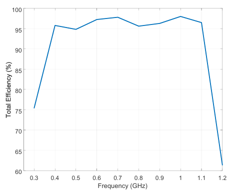
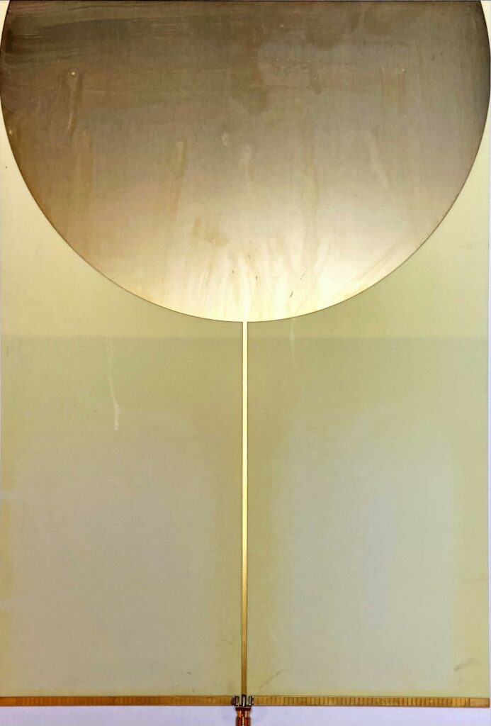
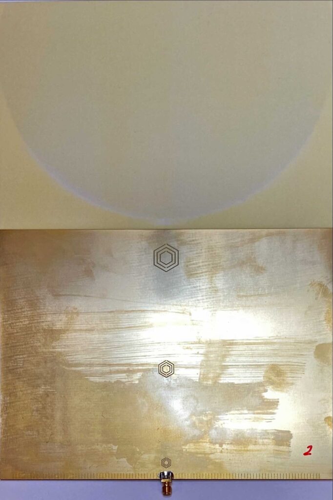
Figure 10: (a) Front view of the manufactured antenna. (b) Back view of the manufactured antenna.
The performance of some of the broadband monopole antennas that are mentioned in the literature and the proposed design are presented in Table 2. Compared to other studies mentioned in Table 2, the proposed structure has the widest operating bandwidth where return loss is below -10dB. One of the essential parameters that indicate the performance of an antenna is the realized gain. In order to evaluate the performance of a wideband antenna, it is better to make an evaluation by using average realized gain. When the average realized gain of the proposed structure is compared with others mentioned in the table, it is seen that the proposed structure performs better than other structures with an average realized gain value of 3.05 dBi except for work in [8]. The reason why the gain of the work in [8] is higher is due to the fact that the aperture of the antenna in [8] is five times larger than the antenna proposed in this work. Another important parameter of an antenna is its size. Although the proposed structure isn’t made to be compact, the final dimensions of the antenna are smaller than the dimensions of most of the antennas mentioned in Table 2.
Table 2: Performance comparison of monopole antennas and proposed monopole antenna.
References | Frequency (MHz) | Average Gain (dBi) | Size (λxλ) |
[1] | 901-930 | 0.85 | 0.24×0.19 |
[2] | 1070-2920 | 2.70 | 0.41×0.22 |
[5] | 2550-3740 | 1.00 | 0.51×0.41 |
[6] | 750-1750 | 2.50 | 0.38×0.35 |
[7] | 860-940 | 0.20 | 0.22×0.29 |
[8] | 5700-16000 | 4.00 | 1.10×1.10 |
[This Work] | 320-1100 | 3.05 | 0.22×0.32 |
3. Conclusion
In this paper, a broadband-printed monopole antenna is proposed. Hexagonal CSRR structures are used to achieve ultrawideband performance. Omni-directional radiation performance is achieved along the whole frequency band. Realized gain with an average of 3.05 dBi and total efficiency of 94% is attained within the whole frequency band. In order to verify the design, the proposed antenna is manufactured and measured. Simulated and manufactured results agree very well with each other, and the operating bandwidth of the proposed antenna is found to be 320 MHz to 1100 MHz.
- C. Sim, J. Zhuang, W. Liao, J. Liou, C. Hsu, J. Huang, “A Coupled-Feed Monopole Antenna for UHF RFID Reader Application,” ISAP 2018 – 2018 International Symposium on Antennas and Propagation, 2019.
- J. T. Rayno, S. K. Sharma, “Wideband frequency-reconfigurable spirograph planar monopole antenna (SPMA) operating in the UHF band,” IEEE Antennas and Wireless Propagation Letters, vol. 11, 2012, doi:10.1109/LAWP.2012.2234871.
- L. Scorrano, A. Manna, D. Spaziani, F. Trotta, P. Naglieri, M. Ferrari, “A novel ultra-wideband UHF low-profile monopole for UAV platforms,” 2015 International Symposium on Antennas and Propagation, ISAP 2015, 2016.
- K. Hiraguri, F. Koshiji, K. Koshiji, “A flexible broadband antenna with fan-shaped and trapezoidal elements formed on printed circuit board for ultra-wideband radio,” 2014 International Conference on Electronics Packaging, ICEP 2014, 2014, doi:10.1109/ICEP.2014.6826794.
- T. Fujimoto, N. Otsuka, C. E. Guan, “A Compact and Broadband Circularly Polarized Printed Monopole Antenna for UHF RFID,” 2021 IEEE International Conference on RFID Technology and Applications, RFID-TA 2021, 2021, doi:10.1109/RFID-TA53372.2021.9617318.
- H. Zhang, G. Zhang, X. Zhang, H. Tian, C. Liu, J. Liu, Y. Zhang, “PD Flexible Built-in High-Sensitivity Elliptical Monopole Antenna Sensor.” Sensors, vol. 22, no. 13, 2022, p. 4982., https://doi.org/10.3390/s22134982.
- Z. Konstas, A. Rida, R. Vyas, K. Katsibas, N. Uzunoglu, M. M. Tentzeris, “A novel ‘Green’ inkjet-printed Z-shaped monopole antenna for RFID applications,” European Conference on Antennas and Propagation, EuCAP 2009, Proceedings, 2009.
- P. Kumar, S. Urooj, F. Alrowais, “Design and implementation of quad-port MIMO antenna with dual-band elimination characteristics for ultra-wideband applications,” Applied Sciences (Switzerland), vol. 10, no. 5, 2020, doi:10.3390/app10051715.
- M. Yayan, A. F. Aslan,” “Design of an Ultrawideband Printed Monopole Antenna Using Hexagonal CSRR at UHF-Band,” 2020 IEEE International Symposium on Antennas and Propagation and North American Radio Science Meeting, IEEECONF 2020 – Proceedings, 2020, doi:10.1109/IEEECONF35879.2020.9330184.