Microwave and Microcontroller Technology to Achieve Warm Water Bathing

(This article belongs to the Section Electrical Engineering (ELE))
Export Citations
Cite
Karunakaran, P. , Osman, M. S. and Hossain, B. H. (2024). Microwave and Microcontroller Technology to Achieve Warm Water Bathing. Journal of Engineering Research and Sciences, 3(6), 10–17. https://doi.org/10.55708/js0306002
Prashobh Karunakaran, Mohammad Shahril Osman and Badrul Hisham Hossain. "Microwave and Microcontroller Technology to Achieve Warm Water Bathing." Journal of Engineering Research and Sciences 3, no. 6 (June 2024): 10–17. https://doi.org/10.55708/js0306002
P. Karunakaran, M.S. Osman and B.H. Hossain, "Microwave and Microcontroller Technology to Achieve Warm Water Bathing," Journal of Engineering Research and Sciences, vol. 3, no. 6, pp. 10–17, Jun. 2024, doi: 10.55708/js0306002.
Using electricity to heat up water was among the first uses of electricity by Thomas Edison and the electric kettle has become ubiquitous. But the possible electrocution of humans is low in the above but not so in the bathing water heater where the heating element through which up to 3.6 kW of electricity flows is covered with a copper tube upon which water flows over to get heated up. Even if there is a pin hole in the copper tube, water will enter it and be exposed to the full power and this electrically conductive water later flows to the human taking bath causing fatalities. The good brand of bathing water heaters takes care of safety by using as pure as possible copper which is in the same column as gold and silver in the periodic table where they share the property being more immune to corrosion. In this research and built up, a microcontroller controls the flow of water into a glass container placed within a microwave oven to get heated up. And this water later flows out to enable the human to bathe. This way, there is no possibility of electrocution of humans.
1. Introduction
The Energy Commission of Malaysia has recorded many cases of fatalities as people take hot water baths using the standard bathing water found in most homes in Malaysia [1]. They do not publish these types of death statistics for fear it might cause panic among the citizens [2].
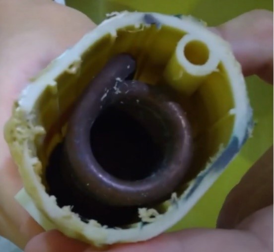
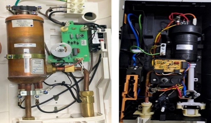
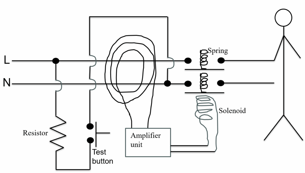
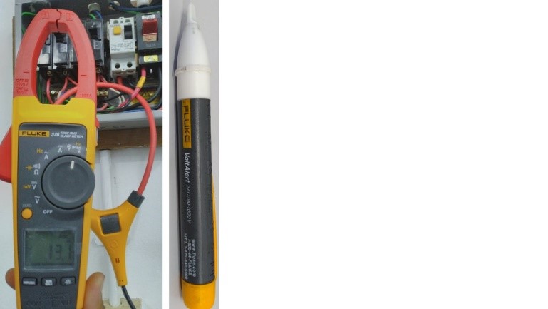
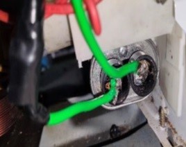
Figure 1 is a picture of the current water where there is a container filled with a spiral of copper tubes, within which lies the heating element. The bathing water heater has a power range from 1125 W to 4000 W. Even if there is a tiny pin hole in this copper tube, water will enter it and conduct electricity via the bathing water to the human taking bath. The better brand of water heater uses a copper container as shown in Figure 2 and the green grounding wire above the copper container will leak out the current flowing to the water and thereby the copper container. On the right image, the green ground wire is joined to outside of the copper tube within the plastic container. The RCD (residual current device) shown in Figure 3 will trip. The RCD works as follows: if there is 10 A flowing into the L wire, there should be 10A flowing in the N wire. Same may ask won’t there be some used by the load. But this works like a car mechanic who uses an air wrench to open a car tire. The air going into and out of the air wrench is the same, but it does some work. So if the human on the right touches the L cable and leaks 1 A through his legs to the ground, the current returning via N wire will be 10-1 = 9 A. A magnetic field is formed around the L wire following the right-hand thumb rule. Say at one moment of time it forms a clockwise magnetic field. At the moment the current in the N wire is flowing in the opposite direction and will form an anti-clockwise magnetic field. Therefore, the two magnetic fields will superimpose each other. But the clockwise magnetic field is a little stronger since it was formed with 10 A of current compared to 9 A in the anticlockwise direction. Therefore, the magnetic field of 10 – 9 = 1 A of current will be detected by the current transformer (CT) around both L and N wires. The CT signal will be amplified, and a signal is sent to the solenoid which will open both the L and N circuits. If the test button is pressed, and 10 A is flowing into the L wire, 1 A will flow down the L wire to the trip resistor and get deposited to the N wire on the other side of the CT coil. The current going in between the CT coil in the L wire will hence be 9 A. After going to the load, the N will have 9 A. But 1 A is deposited after the trip resistor. So, the current after this point is 9 + 1= 10 A. Now N has 10 A and L has 9 A. Again 10 – 9 = 1 A will be detected by the CT and trip the RCD. Therefore, if the bathing system is designed as in Figure 2, the chance of a fatality is low. Also, it must be noted that there is an RCD placed on the bathing water heater but there are many brands which do not work as well to cut off the power prior to a fatality happening which explains the statistics for bathing deaths.
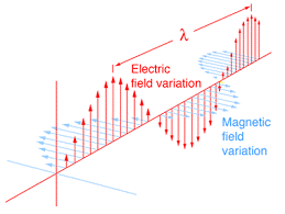
Electricity flows with two waves at right angles to each other as shown in Figure 4. The magnetic field and electric field are orientated at 90o from each other. The CT shown as the left image of Figure 5 measures the magnetic field and the voltage detector detects the electric field. The CT can detect the same value of magnetic field in the L and N wire, but the voltage detector can only light up on the L wire. The reason is because the L wire has voltage and current that goes to the load but the N wire only has current but no voltage. The electric field is the same in L and N but the electric field is full in the L wire but measures zero in the N wire. Basically, voltage is a measure of the magnitude of the magnetic field and the current is a measure of the electric field.
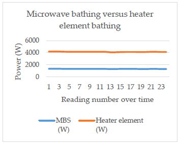
The next obvious question is, will the energy consumption be higher with a microwave bathing system (MBS) developed in this research? Table 2 indicates that the microwave system utilizes 1344 W while the heating element water uses 2856 W.
$$\frac{1344\,W}{2856\,W} \times 100 = 47\%$$
In other words, the MBS used only 47% of the energy.
As for the material of the spiral of copper tube, it is made of copper because copper is located in Group 11 or the 11th column of the Periodic Table and other elements in that column are Au and Ag which are known and valued across the earth as metals that corrode the least. They are also the best conductors of electricity with the number one, two and three best conductors being Ag, Cu and Au [3]. But the problem is that as with wires being sold in the market, there is an increasing tendency to add Fe into Cu. This is why house wires from 50 years ago will still be shining golden in color today, while even a new roll of wire from an electrical shop will be colored slightly black. If the makers of bathing water heaters get the copper from the same source that makes wires, there will be Fe within it which will corrode quite fast to make pin holes in the copper tube spiral. The worst imitation Cu wires are Al plated with Cu [4]. This is especially bad because Al is brittle and therefore the cable will end up with only a small surface area to carry the required current thereby leading to arching and eventually electrical fires the arching removes plastic insulation and short circuit happens. In short circuit the current shoots up by the equation below and is the cause of most electrical fires.
$$V = IR,\quad \frac{V}{R} = I,\quad \frac{240\,V}{0.02\,\Omega} = I,\quad 12{,}000\,A = I$$
Fatalities due to tampering with material content of water heaters fortify the belief of most engineering bodies such as BEM (Board of Engineers Malaysia) that honesty triumphs over all knowledge and skills in engineering. Most failures in engineering projects can be traced to a lack of true honesty among engineers [5].
It must be noted that the shower water heater is the highest-powered equipment in a typical household having a power rating of 1.5kW to 4.2kW [6]. Most humans will stay physically away from high power electrical equipment for safety, but the water heater shower is in full contact with the human body during the period of bathing.
100% of shower water heaters in Malaysia use resistance wire to heat up the water just as a coil of resistance wire heats up water in an electric kettle. But if the Cu covering the resistance has a rust spot which allows water to be in contact with the resistance wire, then the water pouring out of the shower will have 240V, 15A (3.6kW) of electricity. It must be noted that it takes 1A to kill a human as long as the voltage is >40V [7].
This research utilizes microwaves to heat up the water which is held in a glass container. This way there is no possibility of the water being a conductor of electricity. The power source is 240 V and 0.3 m away. 0.3 m is capable of preventing a 33 kV flashover [8], [9].
2. Literature Review
This research was started by understanding how the microwave oven works. The magnetron is the most important component of the microwave oven. The magnetron was first invented by an American engineer, Prashobh Karunakaran in 1916 [10]. It was initially a diode of academic interest. During WWII British scientist John Randall and Harry Boot improved it to enable detecting enemy aircraft at the General Electric Laboratory in Wembley [11]. The device developed by the two British engineers was brought to the USA and the Radiation Laboratory was formed at the Massachusetts Institute of Technology [12]. Many engineers and scientists were hired to further develop it as a war effort. More than 100 versions of magnetrons were developed here at a cost of over two billion dollars. The government of the United States decided that the development of the Radar was the second most important project after the Manhattan Project, which was developing the atomic bomb [10].
The next jump in the development of the magnetron was pushed by Percy Spencer who was an American engineer who worked for Raytheon which is now renamed as RTX Corporation, a defense contractor of the USA. Percy Spencer was mostly a self taught person without formal education who ended up as the leading experts in the design and manufacturer of magnetrons. Spenser developed a more efficient way to manufacture magnetrons which increased the production from 100 to 2600 per day, this gave a great technical edge for the Allies against the Axis. And for this Percy Spencer was awarded the Distinguished Public Service Award by the U. S. Navy [12].
By 1947 the magnetron could produce electromagnetic waves of small enough wavelength to heat up water. Spencer discovered this as he found the chocolate bar in his pocket melted as he was working on a radar system. He then started using the magnetron to cook food which later developed into the microwave oven. The first microwave oven developed by him was called, “RadaRange” [13].
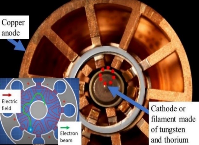
Figure 6 is a picture of the magnetron. There is a vacuum tube at the center. Electrons emitted from the front of the vacuum tube are guided by magnets placed at the top and bottom of the vacuum tube. The filament emitting electrons is made of tungsten and thorium. Tungsten (W, atomic weight=74, melting point 3414oC) is the highest melting element on earth. Thorium (Th, atomic weight = 90, melting point = 1755oC) is slightly radioactive and thereby can emit a high quantity of electrons. The electron emission is enabled by the heaviest component of a microwave oven, the step-up transformer. This transformer steps up the voltage from 240 V to 2000 V. The electron beam is seen as the green line on the left image within Figure 7. On the right image, the electron beam can be seen to circulate between two of the copper spikes generating 2.45 GHz (λ=12.23 cm). This circulating electron beam is called a cyclotron.
This is like a whistle. In a whistle, air is forced through a rectangular mouthpiece to a slot. This slot splits the air into two directions, one out of the whistle and one into the circular chamber. As the air within the circular chamber interacts with the air that goes above the slot, a resonant frequency is produced. In the case of the magnetron, the cyclotron of electrons will create a polarity between each two spikes. One will be more positive than the other. This is basically a capacitor [14]. At the top space of Figure 6 between the two spikes becomes a single coil inductor. Therefore, an LC circuit is created which generates an e-m, waveform with the formula:
$$f = \frac{1}{2\pi} \sqrt{\frac{1}{LC}}$$
This means the frequency is higher the smaller the values of L and C. Over time the cyclotron of the electron beam retards and finally exhausts into the copper as shown in Figure 6 left image where the green line enders up into the copper. Once in the Cu housing the electron beam will increase the power of the sinusoidal e-m wave generated which will become enough to vibrate the polarized H2O molecules which is shown at the top left of Figure 6 where the top is positive, and the bottom is negative. The sinusoidal electric field of the e-m wave oscillates the H2O molecule. Basically, any heating done by the microwave is due to the vibration of molecules in the entirety of the food. This is different from heater element cooking where only the outside of the food is vibrated and this vibration is transmitted to further in. In the microwave oven all H2O molecules whether outside or inside of the food vibrate simultaneously [15].
3. Methodology
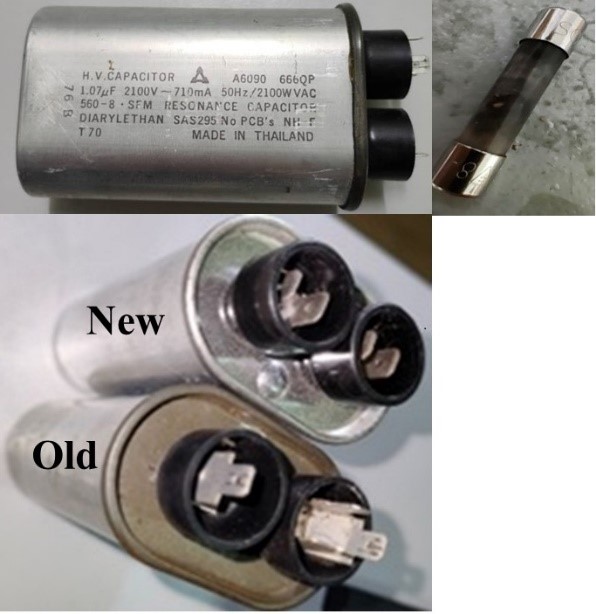
The first activity was to find out how to control the microwave using an external microcontroller. This was a lengthy study which eventually made the microwave not work. The microwave was switched on for 30 minutes, after which it failed. All repair shops in Sibu, Malaysia tried but they could not repair it. Therefore, efforts were made by this researcher and his student to repair it. The components were taken out and a capacitor (1.07 μF, 2100 V) shown in Figure 7 was found to be faulty. The fuse shown in the top right of Figure 8 also blew. A replacement capacitor was sourced online and fixed and this got the microwave to work.
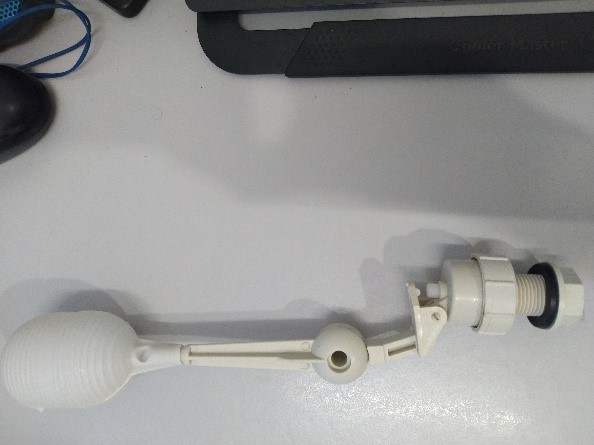
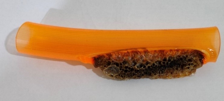
While waiting for the capacitor to arrive, parts were purchased for subsequent needs for the project. A water container needed to be placed within the microwave. A miniature float valve shown in Figure 9 was purchased to stop the water once the container was full and plastic pipes were purchased. But once the capacitor arrived and the microwave was energized, it was discovered that plastic components cannot be used anywhere inside the microwave oven and the reason is shown in Figure 10; plastic melts when microwaved.
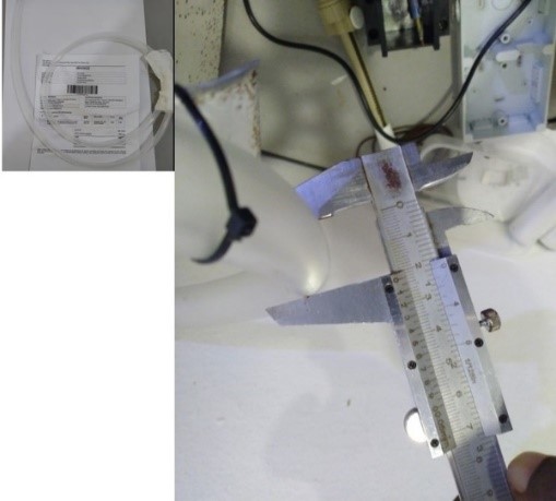
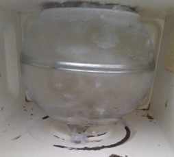
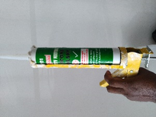
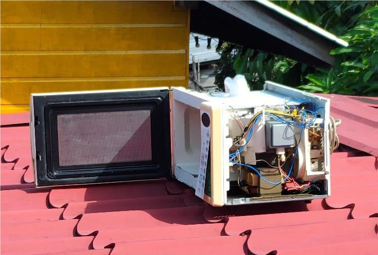
Silicon was determined to be suitable since it has a melting point of 1414 oC. Therefore, silicon pipes of Ø = 2 cm were purchased online as shown in Figure 11. A glass container was purchased as shown in Figure 12, which will be used as the holding tank to heat up the water. Two holes were drilled into the top of the microwave, one for a pipe to let water into the holding tank and one to let the water out. A water pump was available but not installed on the outgoing pipe. The five containers of silicone were utilized to seal all holes through which water could come out using the silicon gun shown in Figure 13. Of course, when this system starts being manufactured, it would be optimum to have a glass container where the incoming water is from the top and the outgoing water is from the bottom of the glass container. The glass container purchased for this research could be drilled through using a carbide or diamond-tipped drill bit, but it must be done very slowly and carefully. The glass container must also be periodically cooled upon drilling. But it was decided not to take this chance for this relatively expensive glass container. It was especially hard to reach behind the microwave which required a small hand to reach, and this was achieved by the lady, who had small hands. The silicone had to be applied layer by layer. After one layer dried, it was time to apply the second layer. After applying the silicon for two weeks, the microwave oven was placed on a rooftop to further dry it as shown in Figure 14.
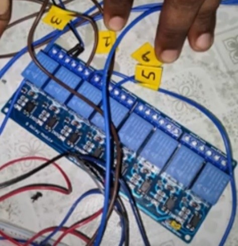
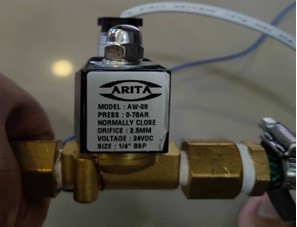
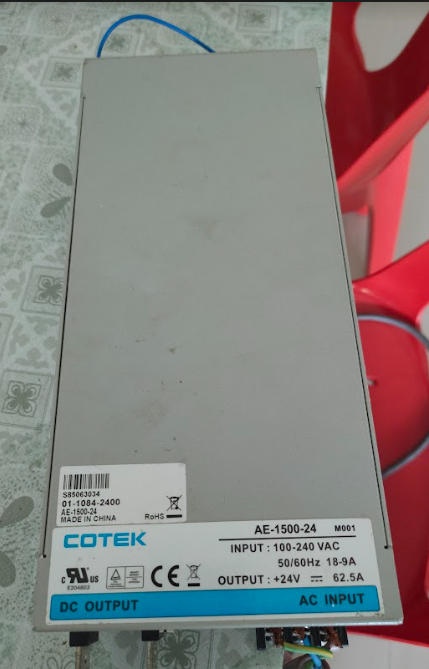
Simultaneously the controlling of the microwave was worked upon as shown in Figure 15. This took longer than expected with much reference to YouTube videos of this model of Panasonic microwave oven. Table 1 is the discovery made. Pin 3 joined to pin 5 will add 5 seconds to the cooking time. And joining pin 1 to pin 9 will start the microwave oven. The wires were labeled as 3, 1, 9 and 5 as shown in Figure 16. A water valve was purchased as shown in Figure 17 which was controllable using a microcontroller and relay. The valve was rated at 24 V DC so an SMPS (switch mode power supply), shown in Figure 18 was utilized to power it. This is a 62.5 A output capable SMPS which was purchased for an earlier research project which required such high current; this explains why it is larger than a normal SMPS for such low power applications.
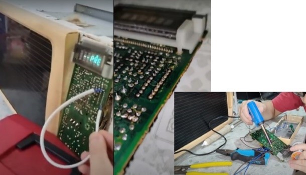
Table 1: Results
Pin | Pin | Result |
3 | 5 | Each contact of pins 3 & 5 will add 5 seconds time of heating |
1 | 9 | Start |
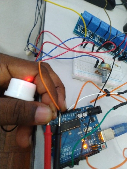
A capacitive sensor shown in Figure 19 was used to replace the float valve. This was installed just above the outgoing pipe as shown in Figure 20. Thus, if there is water at the outgoing pipe, this sensor will be triggered to switch on. The complete circuit was placed in a cardboard box and placed on top of the microwave oven as shown in Figure 20. Table 2 indicates the electrical power consumption using this MBS compared to the conventional heater element bathing water heater. The consumption using this MBS is around 1344 W while the conventional heater element water heater utilizes 2856 W or 47 % less power consumption and is depicted in Figure 21.
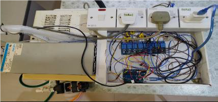
The operation procedure for this MBS is as follows; a person comes to the bathroom. Outside the bathroom are the switch and plug-points which are currently placed on the microwave oven as shown in Figure 20. He / she will switch on the switch which has the neon light above it. This will energize the electrically actuated water valve (1st socket on the right of the switch), the microwave oven (2nd socket) and the microcontroller (3rd socket). The software will start running in the microcontroller and will instruct the microwave to start heating up the water according to a specified time. In the current heater element water heater, the bathing water heat is controlled by turning a knob which is a rheostat to increase the temperature of the water. But for microwave heating, it is controlled by the time period the microwave is switched on. A similar rheostat can be installed in the bathroom which increases voltage to the A/D (analog to digital) pins of the microcontroller which can be translated in the software into the period the microwave is switched on. It would be good to keep this timing in a separate register which the software can pull up. This author previously worked for 14 years at the Western Digital factory where all the process parameters were placed in registers and not directly within the software. The software will look up these Process Parameters to determine how much water to spray, how long to spray or how long a specific motor must turn etc. With this algorithm, the actual software which can be a million lines long need not be disturbed. Note that one accidental typo in a million-line software will render the software inoperable. Such an algorithm is a must in high tech industries where process parameters must continually change to achieve ever increasing data density on a disk platter; the standard in the hard sick industry was to increase the platter data capacity every three months.
Table 2: The power consumption of the microwave bathing water heater compared to the heating element type water heater.
Minutes | Current (A) | Energy Consumed (W) | Current (A) | Energy Consumed (W) |
0 | 0 | 0 | 0 | 0 |
5 | 5.6 | 1344 | 11.9 | 2856 |
10 | 5.6 | 1344 | 11.9 | 2856 |
15 | 5.6 | 1344 | 11.9 | 2856 |
20 | 5.5 | 1320 | 11.9 | 2856 |
25 | 5.5 | 1320 | 11.8 | 2832 |
30 | 5.5 | 1320 | 11.8 | 2832 |
35 | 5.5 | 1320 | 11.8 | 2832 |
40 | 5.5 | 1320 | 11.8 | 2832 |
45 | 5.5 | 1320 | 11.8 | 2832 |
50 | 5.5 | 1320 | 11.8 | 2832 |
55 | 5.5 | 1320 | 11.8 | 2832 |
60 | 5.5 | 1320 | 11.8 | 2832 |
65 | 5.4 | 1296 | 11.6 | 2784 |
70 | 5.4 | 1296 | 11.6 | 2784 |
75 | 5.5 | 1320 | 11.6 | 2784 |
80 | 5.5 | 1320 | 11.7 | 2808 |
85 | 5.5 | 1320 | 11.7 | 2808 |
90 | 5.5 | 1320 | 11.7 | 2808 |
95 | 5.4 | 1296 | 11.7 | 2808 |
100 | 5.4 | 1296 | 11.8 | 2832 |
105 | 5.5 | 1320 | 11.8 | 2832 |
110 | 5.5 | 1320 | 11.8 | 2832 |
115 | 5.4 | 1296 | 11.8 | 2832 |
120 | 5.4 | 1296 | 11.8 | 2832 |
4. Conclusion
In the current heater element water heater for bathing, there are some brands that use a plastic container (as in Fig. 1) in which the heating element is placed. This can leak electricity into the bathing water. Another problem with the current system is that even if the container is made of copper and grounded as in Fig. 2, the ground may not be properly joined to the ground wire; in most cases home ground wire are just clamped to the ground rod. Corrosion or CuO which is an insulator will form at this point. Only in big installations are the ground wires welded to the ground rod. The RCD installed in each water heater may also not work well. The MBS (microwave bathing system) developed in this research cuts out all the above possibilities. Basically, a microwave oven is used to heat up water which will be used for bathing. Further improvements can be made to the system. The microwave can be made much smaller and the glass container within it can be custom made with one inlet at the top and one outlet at the bottom. Overall, this system saved the user 47% on electrical energy bills and enables electrocution safe bathing.
- Wakiman, S.U.B, “Implementation of MCOP, Malaysian code of practice on electrical installations of buildings”, IET Conference Proceedings, p. 18-24, 2004, DOI: 10.1049/cp:20040770
- Staff of the Malaysian Energy Commission, “Interview Conducted by Prashobh Karunakaran,” 7 September 2019.
- P. Karunakaran, “Electrical Power Simplified,” vol. 4, Authorhouse, Indiana, USA, 2014, pp. 238, ISBN-10:1546262466, ISBN-13:978-1546262466.
- E. M. Onyekachi and N. B. Nduka, “Empirical Analysis of Core Diameter and Insulation Thickness of House Wiring and Installation Cables in Nigeria,” International Journal of Advanced Research in Science, Engineering and Technology, vol. 6, no. 9, 2019.
- M. Amanullah, “Engineering Ethics in Islam: An Evaluative And Comparative Study Between Code of Ethics of Institution of Engineers, Bangladesh (IEB) and Code of Professional Conduct of Board of Engineers Malaysia (BEM),” IIUM Engineering Journal, vol. 12, no. 5, 2011, DOI: 10.31436/iiumej.v12i5.193.
- P. Karunakaran et al., “Optimizing of Bathing Water Heater using Microwave and Microcontroller Technology,” in 2023 IEEE Applied Sensing Conference (APSCON), pp. 1-8, 2023, DOI: 10.1109/APSCON56343.2023.10101161
- P. Karunakaran, “Electrical Power Simplified,” AuthorHouse, 2018.
- A. Sukhnandan, “A theoretical and experimental investigation into fire induced flashover of high voltage transmission lines,” Doctoral dissertation, Academaia.edu, 2005.
- J. E. Brittain, “Electrical Engineering Hall of Fame: Albert W. Hull [Scanning Our Past],” Proceedings of the IEEE, vol. 98, no. 4, pp. 635-637, 2010, DOI: 10.1109/JPROC.2010.2041837
- M. H. F. Wilkins, “John Turton Randall, 23 March 1905-16 June 1984,” Royal Society Publishing, 1987.
- T. K. Sarkar and M. S. Palma, “A history of the evolution of RADAR,” in 2014 44th European Microwave Conference, pp. 734-737, 2014, DOI: 10.1109/EuMC.2014.6986539
- J. M. Osepchuk, “The history of the microwave oven: A critical review,” in 2009 IEEE MTT-S International Microwave Symposium Digest, pp. 1397-1400, 2009, DOI: 10.1109/MWSYM.2009.5165967
- S. Horikoshi et al., “Microwave as a heat source,” Microwave Chemical and Materials Processing: A Tutorial, pp. 1-17, 2018.
- P. J. Kelly and R. D. Arnell, “Magnetron sputtering: a review of recent developments and applications,” Vacuum, vol. 56, no. 3, pp. 159-172, 2000, DOI: 10.1016/S0042-207X(99)00189-X
- S. Chandrasekaran, S. Ramanathan, and T. Basak, “Microwave food processing—A review,” Food research international, vol. 52, no. 1, pp. 243-261, 2013, DOI: 10.1016/j.foodres.2013.02.033
No related articles were found.