Experimental Study of the Short-Circuit Current Performance of \(10\,\mathrm{kA_{R.M.S}}\) and \(20\,\mathrm{kA_{R.M.S}}\) Polymer Surge Arrester

(This article belongs to the Special Issue on Special Issue on Multidisciplinary Sciences and Advanced Technology (SI-MSAT 2025) and the Section Electrical Engineering (ELE))
Export Citations
Cite
Sălceanu, C. , Iovan, D. and Ocoleanu, D. (2025). Experimental Study of the Short-Circuit Current Performance of \(10\,\mathrm{kA_{R.M.S}}\) and \(20\,\mathrm{kA_{R.M.S}}\) Polymer Surge Arrester. Journal of Engineering Research and Sciences, 4(12), 15–24. https://doi.org/10.55708/js0412002
Cristian-Eugeniu Sălceanu, Daniela Iovan and Daniel-Constantin Ocoleanu. "Experimental Study of the Short-Circuit Current Performance of \(10\,\mathrm{kA_{R.M.S}}\) and \(20\,\mathrm{kA_{R.M.S}}\) Polymer Surge Arrester." Journal of Engineering Research and Sciences 4, no. 12 (December 2025): 15–24. https://doi.org/10.55708/js0412002
C. Sălceanu, D. Iovan and D. Ocoleanu, "Experimental Study of the Short-Circuit Current Performance of \(10\,\mathrm{kA_{R.M.S}}\) and \(20\,\mathrm{kA_{R.M.S}}\) Polymer Surge Arrester," Journal of Engineering Research and Sciences, vol. 4, no. 12, pp. 15–24, Dec. 2025, doi: 10.55708/js0412002.
To study the behavior of metal oxide surge arresters at short-circuit current, this paper presents an experimental study on four pieces of 36 kV, \(10\,\mathrm{kA_{R.M.S}}\) and \(20\,\mathrm{kA_{R.M.S}}\) surge arresters at different values of short-circuit current. Prior to the experiments, each surge arrester was electrically pre-faulted with a power frequency overvoltage without any physical modification. The tests were conducted under severe conditions at the rated short-circuit current, and the peak value of the first half-cycle of the actual arrester current was at least \(\sqrt{2}\) times the RMS value of the rated short-circuit current. The arrester is one of the most effective means of limiting the lightning surge to the transmission line insulator string and tower head air gap. When an arc occurs, the arrester acts quickly to relieve the high pressure generated by combustion, preventing serious accidents and protecting equipment and maintenance personnel. The purpose of this paper is to experimentally demonstrate whether this type of arrester can prevent cracking and rupture of the enclosure caused by internal arcing effects, thus preventing sudden breakage and dispersal of components outside a controlled area. The arresters were able to extinguish open flames in less than 2 minutes after the test was completed. The paper is important to both arrester designers and end users because it provides an analysis of their short circuit behavior and related phenomena that cannot be adequately simulated.
1. Introduction
Surge arresters are electrical devices designed to protect against electrical surges, which can be classified according to their source: atmospheric surges. Surges of atmospheric origin can be divided into three categories: surges due to direct lightning strikes, surges due to static loads and surges due to indirect lightning strikes; the amplitude of these surges does not depend on the operating voltage.
Switching surges are due to changes in the network configuration and are most often caused by: open circuit of a line, open circuit of a transformer, resonance phe-nomena, interruption of a short circuit, arcing to ground.
The frequency of these voltages depends on the inductance and capacitance of the circuit and is generally much higher than the operating frequency of the net-work. The amplitude of these surges will be reduced if the neutral of the system or transformer is grounded.
The article presents experiments that demonstrate the ability of arresters to withstand high currents for several milliseconds, allowing this type of arrester to protect installations against both atmospheric surges and switching voltages.
Electrical surge arresters are designed to limit atmospheric and switching surges in an electrical installation, protecting equipment in electrical substations such as transformers, circuit breakers, disconnectors, current transformers and voltage transformers. They are connected in parallel with the equipment to be protected and are installed at the entrance to the substation, between phase and earth, and at points where the line changes its characteristic impedance. Their purpose is to safely dissipate surge energy to ground and ensure that the voltage at the terminals remains low enough to protect equipment insulation from the effects of surges.
Most surge arresters used in modern high-voltage systems are of the metal oxide (MO) varistor type.
Surge arresters are designed to keep the voltage below the withstand voltage (the highest voltage that can be applied to equipment without damaging it) and provide an adequate safety margin. However, they cannot limit transient overvoltages (TOV) of frequency or oscillating power. Therefore, they must be designed to withstand these transient overvoltages as well as the maximum system operating voltage without damage.
The surge arrester is one of the most effective devices for limiting lightning surges in transmission line insulator strings and in the tower head air gap [1]-[4]. In the design process of surge arresters, the performance against short-circuit current is an essential technical parameter [5]-[9].
The selection of the rated and low short-circuit current is very important for the arrester design [10]-[12].
If the arrester fails to interrupt the arc at the surge limit or is subjected to an unacceptable operating load during operation, the arc will cause severe vaporization and may burn the silicone rubber coating and internal materials [13]. At this point, the pressure relief valve should be able to act quickly to relieve the high pressure gas from the arc flash, prevent serious explosion accidents caused by the continuous increase in surge arrester internal pressure, and ensure the safety of nearby equipment and patrol personnel.
In recent years, numerous research studies have focused on the placement of surge arresters on power transmission lines. Various methods have been used to evaluate the performance of surge arrester spacers [14]-[18] and to analyze the use of different numbers of arresters per tower [19].
2. Constructive Features
If the arrester fails to interrupt the arc due to overvolt-age, or if it encounters fault conditions, the arc can cause severe vaporization, burning the polymer rubber, breaking the porcelain, and igniting the internal materials [20].
When an arc occurs, the arrester quickly releases the high pressure generated by combustion, helping to prevent major accidents and ensure the safety of equipment and personnel.
Figure 1 shows the wiring diagram of a typical arrester.
The magnetic blowout arrester used in the experi-ments consists of a number of reignition spark gap Eas connected in series with a sub-assembly consisting of the L blowout coil and the non-linear resistor R1 and the main non-linear resistor R2. Each module is shunted by a non-linear resistor R3, which ensures uniform voltage distribution across the modules. If there is no overvoltage, a current of the order of milliamperes flows through resistor R3. When an overvoltage occurs, it primes the Eas spark gaps to the priming voltage.
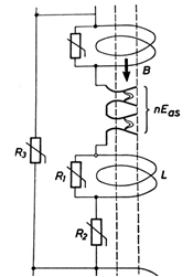
The discharge current flows through the shunt resistor R1 of coil B. No high value current can pass through it because its impedance to the high frequency harmonics of the discharge current is virtually infinite. This current also flows through the main non-linear resistor R2. The highest voltage at the arrester terminals after priming is the residual voltage. After the discharge electrical loads have been discharged to earth, the spark gaps retain their ionization and the associated current passes through the arrester, limited by the R2 resistors to a few hundred amps. The accompanying current, which is at a low frequency of 50 Hz, passes through the magnetic blowout coils L. These cause magnetic induction in the area of the spark gaps, resulting in Lorentz forces that push the arc into slotted blowout chutes with cold walls. The intense cooling of the arc increases its combustion/maintaining voltage and eventually extinguishes it. The accompanying current is determined by the source voltage and the impedance of the short circuit loop, which includes the arc resistance in the spark gaps and the main resistance R2 [21].
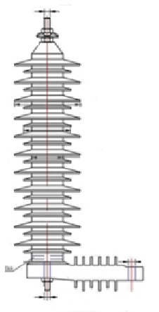
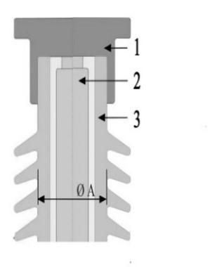
The Type B surge arrester used in the experiments is shown in Figure 2 and Figure 3 shows a Type A porcelain-encapsulated MO surge arrester.
Figure 2 shows the general arrangement drawing of the arrester used in the experiments. In this type of arrester, there is no air gap in the MO.
The MO resistors, which form the active part, are stacked in the centre of the arrester. They were made from a mixture of zinc oxide (ZnO) and other metallic powders, which were then pressed into cylindrical discs. The diameter of each disc determines its ability to withstand surges.
The diameter of the MO is 60 mm. Its main characteristic is the voltage current non-linearity.
The endurance capacity, which is determined by the arrester rated voltage, together with the switching and lightning protection levels, determines the height of the MO resistors, which are mounted with aluminum tube spacers to ensure uniform contact pressure distribution. The MO resistance column is supported by multiple fi-berglass-reinforced plastic support rods and mounting plates. Axial pressure is maintained by a spring located at the top of the arrester. The sealing device is integrated into the cemented flanges at both ends of the arrester.
The endurance capacity, which is determined by the arrester rated voltage, together with the switching and lightning protection levels, determines the height of the MO resistors, which are mounted with aluminum tube spacers to ensure uniform contact pressure distribution. The MO resistance column is supported by multiple fi-berglass-reinforced plastic support rods and mounting plates. Axial pressure is maintained by a spring located at the top of the arrester. The sealing device is integrated into the cemented flanges at both ends of the arrester.
This type of arrester is not directly grounded, but is connected in series with various monitoring devices. As shown in Figure 2, the bottom flange of the arrester is mounted with insulating feet and the ground connection is made via a special grounding device. This component of the arrester was eliminated during the short-circuit test.
When a transmission line conductor is subjected to a short-circuit ground fault, the inductance L of the ground wire can be determined according to [1]. The distance Ds and the equivalent radius rm can be calculated according to references [1] and [3].
$$L = \frac{\mu_0}{2\pi} \left[ \ln\frac{1.8514}{D_s \sqrt{2\pi f \mu_0 \sigma}} + \frac{4h \sqrt{\pi f \mu_0 \sigma}}{3} \right] \tag{1}$$
$$D_s = \sqrt[n]{1.414213\, r_m\, d_n^{\,n-1}} \tag{2}$$
$$r_m = e^{\frac{1}{4} r} = 0.779\, r \tag{3}$$
where: L – pole inductance under phase to earth fault (H/m); m0 – vacuum permeability (H/m); Ds – cable length; s – earth conductivity (S/m); f– frequency (Hz); r– equivalent cable radius (m).
On the other hand, the electromotive induction force generated by the short-circuit current through an inductive connection on a line can be calculated as follows:
$$E = \sum_{i=1}^{n} \omega M_i l_i I_s s t \tag{4}$$
where: E– line inductance (V); w – apparent frequency (rad/s); Mi – mutual inductance (H/km); li – line distance in km; Is – sum of the frequency components of the short-circuit current (A). Given the line voltage Ud, we can calculate the short-circuit current Isc in (A):
$$I_{sc} = \frac{U_d}{\omega} \left[ \frac{1}{L_d + \sum_{i=0}^{n} l_i L} + \frac{k_f \sum_{i=0}^{n} l_i}{L_d} \right] \tag{5}$$
assuming that the structural coefficient of the line kf is 0.25.
Ld is the inductance of the circuit (H) and l is the total length of the transmission line (km).
The next section analyzes the arrester’s ability to re-duce pressure in the event of a short circuit. Tests have confirmed the arrester’s effectiveness in protecting nearby equipment. According to the source (5), the short-circuit current varies according to the position of the arrester. When it is close to the transformer, the short-circuit current reaches a maximum of 20 kA and decreases to 12 kA or 6 kA as the distance increases. After a certain distance, the variations become insignificant and the current value stabilizes in the range of 600 ± 200 A.
3. Short Circuit Tests
Experiments were conducted on identical specimens, as shown in Figure 2, to determine whether an arrester malfunction could cause a violent burst of the enclosure and whether the flames generated could be extinguished in a controlled manner within a predetermined time interval. The arrester was not equipped with additional devices to replace conventional overpressure mechanisms.
According to [19], the arrester is classified as type “B”, made of polymeric material, with a solid construction and without a closed gas volume. When MO (metal oxide) resistors fail electrically, an internal arc is formed, resulting in accelerated vaporization and eventual ignition of the case and materials inside.
The purpose of this paper is to experimentally demonstrate whether this type of arrester can control the cracking and rupture process of the enclosure caused by internal arcing effects, thus preventing violent rupture and dispersion of components beyond a welldefined area.
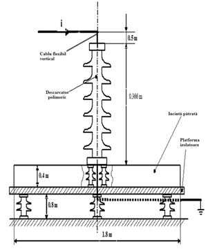
The circuit used for the experiments, shown in Figure 4, was designed according to the applicable standards [19], taking into account the most unfavorable installation conditions of arresters in electrical substations.
Type A arresters have a volume of air greater than 50% along the active side and are prepared for short-circuit testing with a fusible wire connected between their ends.
Type B arresters, which have less than 50% air volume around the active part, are prepared for short-circuit testing by a pre-fault process. This process consists of applying a voltage characteristic of each type of arrester. The purpose of pre-fault is to provide sufficient electrical conductivity to allow the short-circuit current to pass at a voltage below the rated voltage [22].
In the first stage, the arresters 36 kV, 10 kA were subjected to an electrical pre-fault process by applying an industrial-frequency surge voltage without any special preparation.
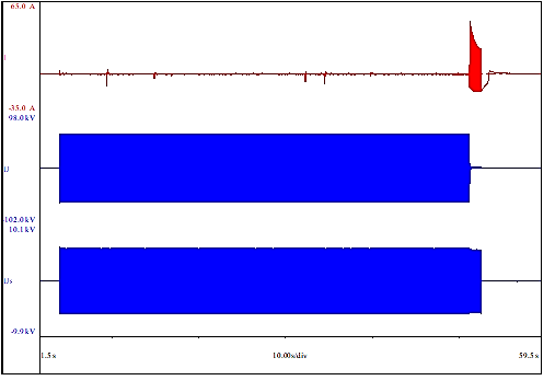
Figure 5 shows the oscilloscope reading for the first arrester, the others are similar. The circuit was previously calibrated to 18 AR.M.S and 43 kVR.M.S.
For example, the voltage applied until the arrester pre-failed was 43 kVR.M.S for 47.27 seconds, after which a current of 18.65 A R.M.S. occurred and was maintained for 1.41 seconds [22].
For the short-circuit tests, the arrester was mounted as shown in Figure 4, with the lower end of the arrester flush with a 1.8 m wide square enclosure. The base used for the experiment was made of insulating material and placed on an insulating platform.
In the first test, conducted at rated short-circuit current, the applied voltage was less than 77% of the arrester’s rated voltage. To meet the test conditions, the circuit pa-rameters were adjusted so that the RMS value of the symmetrical current component was at least equal to the required current level. This resulted in the oscillographic recording shown in Figure 6.
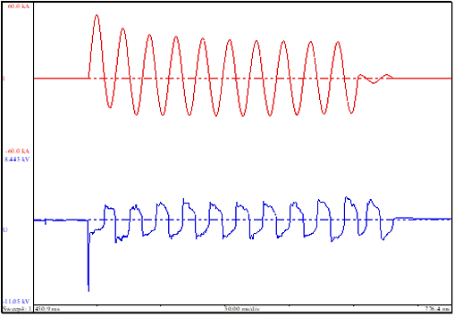
Parameters obtained: applied voltage U=22.1 kVR.M.S.; peak current Ipeak=50.2 kA; short-circuit current
Isc= 20.9 kAR.M.S; voltage drop Udrop=1.78 kVR.M.S and arc duration t=0.21 s.
It is observed that the peak value of the current in the first half-cycle exceeds , these values being difficult to obtain under normal conditions for polymer type B arresters. In order to achieve these values in a high power laboratory, a short-circuit generator with a capacity of 2500 MVA was used, together with precise excitation control.
To maintain optimal test conditions, the test was performed less than 15 minutes after the pre-fault process to prevent the arrester from cooling.
The experiment was considered successful otherwise it should have been repeated, ensuring a sufficiently low arrester impedance by applying a pre-fault current no more than 2 seconds before applying the short-circuit current. As part of the pre-fault process, it is permissible to increase the short-circuit current up to 300 AR.M.S. In this case, the maximum duration, depending on the magnitude of the current, must not exceed the following value:
$$t_{rpf} \leq \frac{Q_{rpf}}{I_{rpf}} \tag{6}$$
In (6), trpf is the pre-fault time in seconds; is the pre-fault load = 60As; Irpf is the pre-fault current in amps.
Further tests were conducted at reduced currents, applying a voltage of less than 77% of the arrester’s rated voltage. The circuit parameters have been set so that the RMS value of the symmetrical current component is at least equal to the required current level.
According to [19], for arresters with a rated current of 10 kAR.M.S and a rated short-circuit current of 20 kAR.M.S, the discharge current is 20, 10 or 5 kAR.M.S and the reduced short-circuit currents have the following values: 12000±10%, 6000±10% and 600±200 AR.M.S.

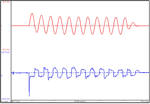
Parameters obtained on another arrester, previously pre-faulted, under the same conditions, on the oscilloscope recording in Figure 7 for an assumed current of 12000 AR.M.S: applied voltage U=19.8 kVR.M.S; peak current Ipeak = 26.7 kA; short-circuit current Isc =12.4 kAR.M.S; voltage drop Udrop=1.83 kVR.M.S and arc duration t=0.22 s.
Parameters obtained on another arrester, previously pre-faulted, under the same conditions, on the oscilloscope recording in Figure 8 for an assumed current of 6000 AR.M.S: applied voltage U=22.8 kVR.M.S; peak current Ipeak=12.5 kA; short-circuit current Isc= 6.1 kAR.M.S; voltage drop Udrop=1.48 kVR.M.S and arc duration t=0.22 s.
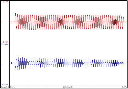
Parameters obtained on another arrester, previously pre-faulted, under the same conditions, on the oscilloscope recording in Figure 9 for an assumed current of 600 AR.M.S: applied voltage U=20.5 kVR.M.S; peak current Ipeak=1.02 kA.; short-circuit current Isc= 0.59 kAR.M.S, 0.1 seconds after a short-circuit has occurred; voltage drop Udrop=1.48 kVR.M.S, and arc duration t=1.04 s.
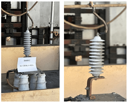
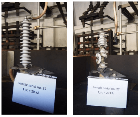
In all the tests carried out, the arresters were installed and the conductors laid under the most unfavorable op-erating conditions. Figure 10 show photos taken before and after tests.
The earth conductor has been oriented in the opposite direction to the incoming conductor (Figure 10), so the arc will remain close to the arrester for the duration of the short-circuit current, creating the most unfavorable conditions in terms of fire risk.
The research continued on a 36 kV, 20 kA to establish the traceability of the experiments. The experiments were performed in the same conditions as previous, according to [19], presented in Figure 4.
The surge arrester was pre-failed in the same conditions as the previous one. The experiments were made at 24 kV applied voltage, measured between phases. Experiments performed: rated Short-Circuit current 20 kA, reduced short-circuit current 12 kA, reduced short-circuit current 6 kA and short-circuit low current 600 A.
After circuit calibration, the Rated current short-circuit test on first sample was performed with structural failure on upper part, all parts remained inside the enclosure.
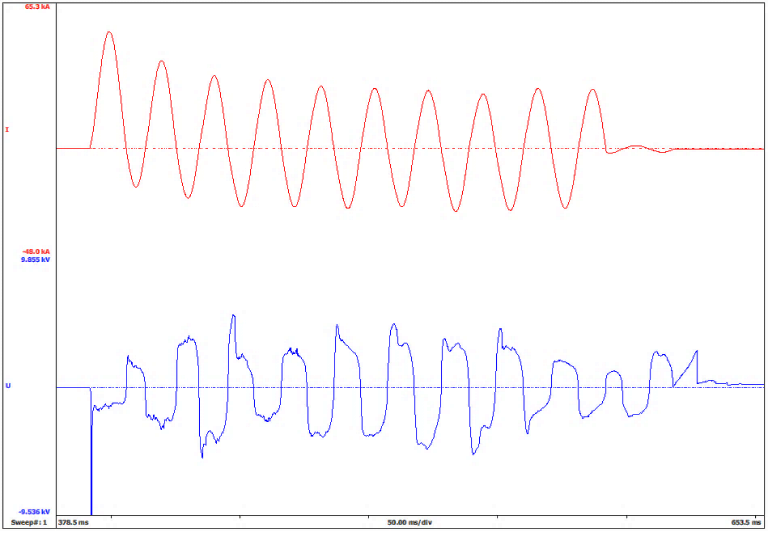
Parameters obtained in the oscilographic recording presented in Figure 11 are: applied voltage U= 24.1 kVR.M.S; peak current Ipeak= 52.1 kA; short-circuit current Isc= 20.9 kAR.M.S; voltage drop Udrop=2.83 kVR.M.S, and arc duration t= 0.2 sec.
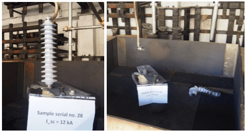
Next experiment is reduced current short-circuit test on different sample, where structural failure on upper and lower part, all parts remained inside the enclosure.
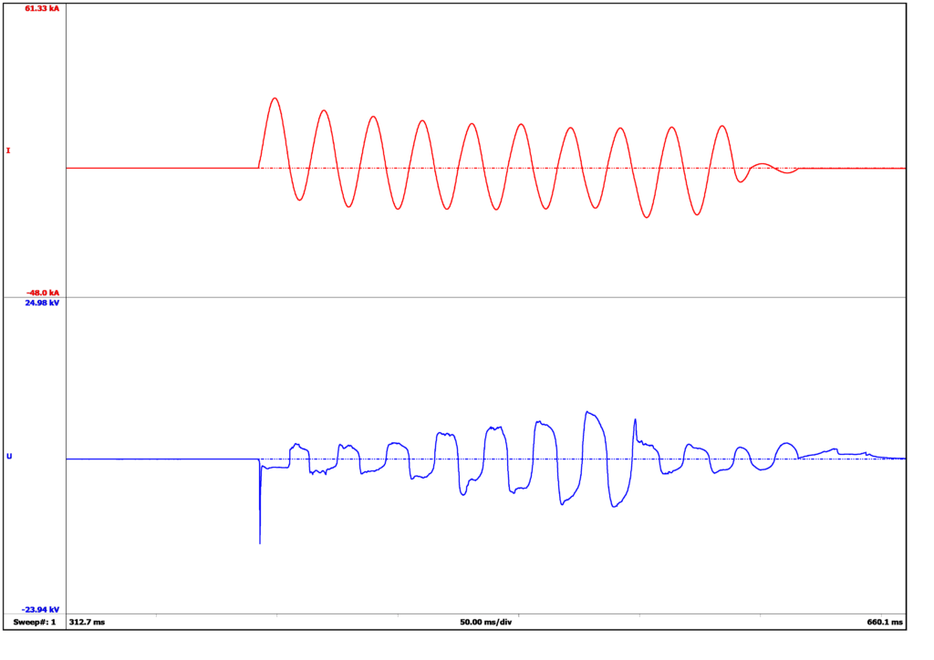
Parameters obtained in the oscilographic recording presented in Figure 12 are: applied voltage U= 24.1 kVR.M.S; peak current Ipeak= 26.1 kA.; short-circuit current Isc= 12.1 kAR.M.S; voltage drop Udrop= 3.42 kVR.M.S, and arc duration t= 0.2 sec.
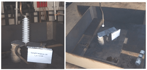
Next experiment is reduced current short-circuit test on different sample, where structural failure on upper and lower part, all parts remained inside the enclosure.
Figure 13: Oscillographic recording of reduced short-circuit current test
Parameters obtained in the oscilographic recording presented in Figure 13 are: applied voltage U= 24,2 kVR.M.S; peak current Ipeak= 12.1 kAR.M.S.; short-circuit current Isc= 6.1 kAR.M.S; voltage drop Udrop= 4.1 kVR.M.S, and arc duration t= 0.2 sec.
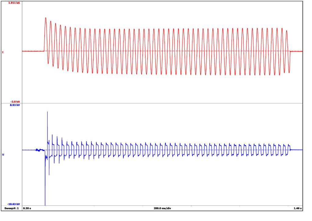
Next experiment is low current short-circuit test new sample. The open flames resulted after test self-extinguish in less than 1 minute.
Parameters obtained in the oscilographic recording presented in Figure 14 are: applied voltage U= 24.1 kVR.M.S; peak current Ipeak= 1.3 kA.; short-circuit current Isc= 0.6 kAR.M.S; voltage drop Udrop= 0.9 kVR.M.S, and arc duration t= 1 sec.
Considering the results obtained we can conclude that this value of short-circuit current is the maximum value that can be applied on this type of construction. Even tho according to [21], the results are considered fulfilled, we consider the parts that detached might endanger the personal.
Photos from the experiments are presented in figures 15 to 17.
4. Discussions and Conclusions
The electricity transmission system is essential to ensure a continuous and stable flow of electricity to consumers. However, extreme weather conditions, voltage fluctuations, or equipment failures can affect the safety and reliability of this system. One of the most effective technical solutions for protecting electrical infrastructure and preventing major disturbances is surge arresters, which can make a significant contribution to improving the reliability of electrical grids. In this context, it is important to understand their role and impact on the protection of the transmission system.
Surge arresters are devices designed to protect electrical equipment from surges that can occur for a variety of reasons, such as lightning strikes, switching equipment maneuvers, or network faults. They are installed in power grids, both in substations and at various points in distribution networks. Surge arresters work by absorbing and dissipating the extra energy generated by a surge, protecting transformers, cables and other equipment from serious damage.
Lightning is a major cause of power surges in electrical grids. These can cause sensitive equipment such as transformers and circuit breakers to fail quickly. Surge arresters are essential to protect these components from the damaging effects of lightning by quickly absorbing and dissipating the excess energy generated during a lightning strike. This prevents serious malfunctions that could lead to major power losses and prolonged power outages.
Surges can be caused not only by natural phenomena, but also by equipment switching maneuvers or network faults. In these situations, surge arresters provide immediate protection and limit the negative impact on equipment. By intervening quickly when voltage exceeds safe limits, these devices help ensure continuous system operation without costly interruptions or failures.
Another significant benefit of using surge arresters is the extended life of electrical equipment. Frequent and irregular power surges can accelerate component wear and lead to premature component failure. By protecting equipment from these voltages, surge arresters reduce the frequency of maintenance and parts replacement, helping to optimize power system operating costs and minimize downtime.
A reliable power transmission system must be able to respond quickly to voltage fluctuations and prevent them from spreading throughout the network. Surge arresters play a critical role in maintaining the stability of power systems by ensuring that local surges do not propagate and cause cascading failures. This helps reduce the risk of long-term power outages and protects the integrity of the entire transmission system.
Surge arresters are essential tools for improving the reliability of the power transmission system. By protecting electrical networks and equipment from dangerous surges, these devices help prevent failures, extend equipment life and maintain the stability of electrical networks. The effective integration of surge arresters into the power infrastructure is therefore an important step towards a safer, more reliable and more resilient power transmission system.
Installing surge arresters increases the reliability of the power transmission system, but requires additional capital investment. To determine the most efficient and cost-effective arrangement of surge arresters in a pro-tected transmission line, it is suggested that the arresters be placed according to the resistance characteristic of the transmission line tower foot, so that the entire transmission line can be divided into several line sections. Each line section consists of towers of similar resistance. As proposed in [22], two different concepts are considered for lightning protection:
(a) Install a different number of surge arresters on se-lected phases of each tower;
(b) Install arresters on all selected tower phases.
By varying the number of towers to be equipped or the number of phases to be equipped with surge arresters, the threshold voltage is used to evaluate different surge arrester installation configurations.
As mentioned in [20], towers are more likely to be built on ridges to facilitate construction. Therefore, it is not very effective to reduce the tower ground impedance at the top of the ridge, where the tower foot impedance is generally highest. Thus, it is very likely that the ground resistances of towers on a ridge will be different from the resistances at the base of adjacent towers. The resistance of the base has a significant effect, both positive and negative, on the insulator voltage in different situations. For towers with high resistance at the base, it is recommended to install surge arresters with better energy dissipation capacity. In addition, if the resistance at the base of the towers varies, the negative effect of the base resistance on lightning performance cannot be neglected.
Therefore, if the towers have different resistances at the base near the boundaries of each protected section, it is recommended that surge arresters be installed on each tower to prevent damage. Within each line section, different arrester configurations are used to improve performance. One configuration model is to install a varying number of arresters on selected phases of all towers. For this type of design, simulation results show that the insulators on the upper phase are most susceptible to flashover. Therefore, it is recommended that arresters be installed on the upper phases. The effect of the number of arresters per tower is studied in the literature using three different configurations. A proper and more efficient arrester configuration can be determined using the voltage diagram and voltage threshold as a function of base resistance.
The main difference between the surge behavior of high-voltage and medium-voltage MO arresters is the energy absorbed during the discharge period when sub-jected to different types of surges. High-voltage MO arresters are particularly stressed by switching surges, which cause a large portion of the electrical load to pass through the arrester during the entire surge period. On the other hand, medium-voltage arresters are mostly stressed by direct lightning strikes in the vicinity of the protected object. For high-voltage MO surge arresters, there are standard methods for determining the energy absorption capacity based on estimating the line discharge energy.
The energy absorbed by the medium-voltage arrester due to lightning discharges can be estimated by analytical methods.
Experimental energy absorption capacities of arresters for AC and impulse currents are presented in [22]. The product “Ixt” was found to be constant, where I is the current and „t” is the pulse duration. Due to the increase in residual voltage as the applied current increases, the energy absorption capacity also increases, almost tripling when large pulses of lightning impulse are applied instead of small, long duration currents.
Tests show favourable behaviour after the occurrence of a short-circuit current. The performance achieved was largely determined by the non-linearity of the resistors and the accuracy of spark gap ignition and quenching. Since the resistances are non-linear, the conduction of electric charges to earth in the form of impulse current is faster, and in the final stage of electric charge transport, the resistance reaches high values that favour the extinction of the electric arc.
During the tests, there was no violent breakage, and no part of the arrester, such as pieces of polymer materials or MO resistors, was found outside the test enclosure. Electrical arresters were able to extinguish naked flames within 2 minutes of the end of each test
Conflict of Interest
The authors declare no conflict of interest.
Acknowledgment
This research was funded by the Ministry of Research, Innovation and Digitization of Romania as part of the NUCLEU Program: PN 23 33 02 01.
- G. S. Gu, S. Wan, Y. Wang, X. Chen, W. Cao and J. Wang, “Study S. Gu, S. Wan, Y. Wang, X. Chen, W. Cao and J. Wang, “Study on Short-Circuit Current Performance of ±500kV DC Transmission Line Surge Arrester,” 2019 11th Asia-Pacific International Conference on Lightning (APL), Hong Kong, China, 2019, pp. 1-5, doi: 10.1109/APL.2019.8816066.
- Q. Xia and G. Karady, “An Efficient Surge Arrester Placement Strategy to Improve the Lightning Performance of Long Transmission Line,” 2020 IEEE Power & Energy Society General Meeting (PESGM), Montreal, QC, Canada, 2020, pp. 1-5, doi: 10.1109/PESGM41954.2020.9281691.
- K. S. Shreyas and S. Reddy B., “Multistress Ageing Studies on Polymeric Housed Surge Arresters,” 2020 IEEE International Conference on Electronics, Computing and Communication Technologies (CONECCT), Bangalore, India, 2020, pp. 1-4, doi: 10.1109/CONECCT50063.2020.9198354.
- B. S. Ibrahim, D. M. Soomro, S. Sundarajoo and M. N. Akhir Tahrir, “Lightning and Surge Arrester Simulation in Power Distribution System,” 2023 IEEE 8th International Conference on Engineering Technologies and Applied Sciences (ICETAS), Bahrain, Bahrain, 2023, pp. 1-4, doi: 10.1109/ICETAS59148.2023.10346344.
- R. Mori and A. Tatematsu, “Response of a Surge Arrester With a Series Gap for 6.6-kV Distribution Lines to Steep-Front Transients,” in IEEE Transactions on Electromagnetic Compatibility, vol. 64, no. 6, pp. 2296-2300, Dec. 2022, doi: 10.1109/TEMC.2022.3202155.
- C. Chuayin, M. Zinck, A. Kunakorn and N. Pattanadech, “Study of Asymmetrical Leakage Currents of Metal Oxide Surge Arrester due to Multiple Current Impulses,” 2020 International Symposium on Electrical Insulating Materials (ISEIM), Tokyo, Japan, 2020, pp. 305-308.
- Trotsenko, Y., Brzhezitsky, V., & Mykhailenko, V. (2020). Estimation of Discharge Current Sharing Between Surge Arresters with Different Protective Characteristics Connected in Parallel. 2020 IEEE 7th International Conference on Energy Smart Systems (ESS), 73-78.
- L. Wang, K. Wan, L. Chen, Q. Qian and J. Huang, “Analysis about Potential Distrib S. Gu, S. Wan, Y. Wang, X. Chen, W. Cao and J. Wang, “Study on Short-Circuit Current Performance of ±500kV DC Transmission Line Surge Arrester,” 2019 11th Asia-Pacific International Conference on Lightning (APL), Hong Kong, China, 2019, pp. 1-5, doi: 10.1109/APL.2019.8816066.
- V. V. Waghmare, V. K. Yadav and I. M. Desai, “Optimization of Grading Ring of Surge arrester by using FEM method, PSO & BAT Algorithm,” 2022 2nd International Conference on Advance Computing and Innovative Technologies in Engineering (ICACITE), Greater Noida, India, 2022, pp. 367-370, doi: 10.1109/ICACITE53722.2022.9823652.
- M. Y. Ataka, L. L. Bacci, T. M. Lima, R. F. R. Pereira, E. C. M. Costa and L. H. B. Liboni, “Lighting Protection of VSC-HVDC Transmission Systems using ZnO Surge Arresters,” 2020 IEEE Canadian Conference on Electrical and Computer Engineering (CCECE), London, ON, Canada, 2020, pp. 1-5, doi: 10.1109/CCECE47787.2020.9255785.
- H. Fujita, K. Michishita, S. Yokoyama, K. Kanatani and S. Matsuura, “Damage Threshold of Surge Arrester Depending on Configuration of Power Distribution Line,” 2021 35th International Conference on Lightning Protection (ICLP) and XVI International Symposium on Lightning Protection (SIPDA), Colombo, Sri Lanka, 2021, pp. 01-06, doi: 10.1109/ICLPandSIPDA54065.2021.9627402.
- N. Abdullah, M. F. Ariffin, N. M. Hatta, M. F. Nozlan, A. Mohamad and M. Osman, “Surge Arrester Monitoring Implementation at 33kV Distribution Overhead Line in Malaysia,” 2023 12th Asia-Pacific International Conference on Lightning (APL), Langkawi, Malaysia, 2023, pp. 1-3, doi: 10.1109/APL57308.2023.10181389.
- A. Munir, Z. Abdul-Malek and R. N. Arshad, “Resistive Leakage Current Based Condition Assessment of Zinc Oxide Surge Arrester: A Review,” 2021 IEEE International Conference on the Properties and Applications of Dielectric Materials (ICPADM), Johor Bahru, Malaysia, 2021, pp. 183-186, doi: 10.1109/ICPADM49635.2021.9493979.
- J. Ndirangu, P. Kimemia, R. Ndolo, J. Nderu and G. Irungu, “Appropriate Surge Arrester Lead Lengths for Improved Distribution Transformer Protection — Kenyan Case Study,” 2020 IEEE PES/IAS PowerAfrica, Nairobi, Kenya, 2020, pp. 1-4, doi: 10.1109/PowerAfrica49420.2020.9219990.
- P. Gupta, G. N. Reddy and S. Reddy B, “Multi-stress Aging Studies on Polymeric Surge Arresters for HVDC Transmission,” 2021 IEEE 5th International Conference on Condition Assessment Techniques in Electrical Systems (CATCON), Kozhikode, India, 2021, pp. 176-180, doi: 10.1109/CATCON52335.2021.9670490.
- J. P. P, C. Prabhakar, B. V. Nagachandra and G. Pandian, “Failure Analysis of Metal Oxide Surge Arrester Blocks Based on Repetitive Charge Transfer Rating Verification Test,” 2022 12th International Conference on Power, Energy and Electrical Engineering (CPEEE), Shiga, Japan, 2022, pp. 22-26, doi: 10.1109/CPEEE54404.2022.9738705.
- M. Moghbeli, S. Mehraee, S. Sen, Application of Surge Arrester in Limiting Voltage Stress at Direct Current Breaker. Appl. Sci. 2024, 14, 8319. https://doi.org/10.3390/app14188319.
- H. Zhou et al., “Electromagnetic Simulation and Characterization of Network-type 10kV Surge Arresters,” 2023 5th International Conference on System Reliability and Safety Engineering (SRSE), Beijing, China, 2023, pp. 513-519, doi: 10.1109/SRSE59585.2023.10336153.
- IEC 60099-4:2014 Surge Arresters — Part 4: Metal-oxide Surge Arresters Without Gaps for A.C. Systems.
- M. S. Savic, “Estimation of the surge arrester outage rate caused by lightning overvoltages,” in IEEE Transactions on Power Delivery, vol. 20, no. 1, pp. 116-122, Jan. 2005, doi: 10.1109/TPWRD.2004.835435.
- E. C. Sakshaug, J. J. Burke and J. S. Kresge, “Metal oxide arresters on distribution systems: fundamental considerations,” in IEEE Transactions on Power Delivery, vol. 4, no. 4, pp. 2076-2089, Oct. 1989, doi: 10.1109/61.35633.
- C. -E. Sălceanu, D. Iovan, M. Ionescu, D. -C. Ocoleanu and Ş. Şeitan, “Analysis on the Behaviour of 36 kV, 10 kA Pre-failed Polymer Surge Arrester at Short-Circuit Current,” 2024 International Conference on Applied and Theoretical Electricity (ICATE), Craiova, Romania, 2024, pp. 1-6, doi: 10.1109/ICATE62934.2024.10749034.