PWM Controlled Bidirectional Converter having Load-Independent Voltage-Gain

(This article belongs to the Special Issue on Special Issue on Multidisciplinary Sciences and Advanced Technology (SI-MSAT 2022) and the Section Electrical Engineering (ELE))
Export Citations
Cite
Riaz, M. T. , Saeed, U. , Waseem, S. , Riaz, S. and Ahmed, E. M. (2022). PWM Controlled Bidirectional Converter having Load-Independent Voltage-Gain. Journal of Engineering Research and Sciences, 1(5), 34–40. https://doi.org/10.55708/js0105004
Muhammad Tanveer Riaz, Umar Saeed, Saba Waseem, Sidra Riaz and Eman Manzoor Ahmed. "PWM Controlled Bidirectional Converter having Load-Independent Voltage-Gain." Journal of Engineering Research and Sciences 1, no. 5 (May 2022): 34–40. https://doi.org/10.55708/js0105004
M.T. Riaz, U. Saeed, S. Waseem, S. Riaz and E.M. Ahmed, "PWM Controlled Bidirectional Converter having Load-Independent Voltage-Gain," Journal of Engineering Research and Sciences, vol. 1, no. 5, pp. 34–40, May. 2022, doi: 10.55708/js0105004.
The power balancing is the issue that creates when voltage fluctuations occur in the DC microgrid. In order to compensate for the DC bus voltages in the DC microgrid, the energy storage system is used. This system absorbs or releases the power to make the DC bus voltages is stable. In this research, a bidirectional series resonant (BSR) converter is proposed which operates at the fixed frequency for the energy storage system. A simple PWM control technique is used for the power flow regulation in the system. The gain voltage of the BSR converter depends only on the duty cycle of the applied voltage and does not change the direction and amplitude of the power flow. Theoretically, after the calculations, the gain voltage of the BSR converter changed from minimum (zero) to maximum (unlimited) which means the designed converter is a buck-boost converter as well. This property of the BSR converter will help the researcher to use a wide range of voltage applications. The operations mode i.e. forward and backward modes, and the direction of the power flow can be changed smoothly by Pulse Width Modulation control. Zero voltage switching for all the voltage ranges of the active switches is also achieved in this research.
1. Introduction
Gadgets such as batteries and supercapacitors which do store energy, capable of enduring or interim energy buffering has been a critical part in numerous DC microgrids. The key device to interface storage batteries or super-capacitors with a DC voltage bus in a DC microgrid is a bidirectional DC-DC converter (BDCs). Moreover, BDCs needs more voltage gain because of extensive variation of terminal voltages in the batteries and super-capacitors. So, it’s a research gap was available in the last few years in order to get a high efficacy in the BDCs for the wide range of voltage gain in the applications of DC microgrid. Although, an isolated BDC is also available in the market which considered as a better form of unidirectional converter (DC-DC). It can be designed as by replacing the rectify diodes with active switches. Keeping in mind of this given principle, many varieties of remoted BDCs are designed in the years i.e. PWM controlled BDCs, resonant BDCs, phase shift DAB (Dual-Active-Bridge) BDCs etc. From these BDCs, DAB BDC has gain more attraction towards research because of its many advantages like flexibility present for controlling the Buck-Boost converter, small voltage stresses exist on the switches and turn-on losses reduce in the switching (by zero-voltage switching (ZVS)). The phase shift angle between primary and secondary switching is used to control the direction and amplitude in the power flows. However, this type of BDCs also limited due to presence of high circulating currents in the transformers and semiconductors devices that keep turn-off current losses high. Phase shift manipulation techniques also work to adjust the circulating current but, in this case, ZVS performance does not meet expectations among the whole operation. Resonant BDC (LC series-resonant tank) can be used to reduce the turn-off current losses if purely sinusoidal current finds in the resonant tank. But still problem exist in the resonant BDC i.e. exceeds circulating current and increased turn off losses when increases the phase-shift angle.
Saving the domestic electrical energy consumed by the DC gadgets in thou- sands of AC to DC conversions by just doing one conversion in DC microgrid system. The Bidirectional DC to DC converter can be used on HVDC level because bidirectional gain independent converters promise a feasible and re- liable solution for energy conservation and sharing. This project can be marketed in future when DC microgrid will be a part of Distribution System Due to the quality of bidirectional power flow, this project can be used for power exchange between two countries on HVDC lines.
To implement a bidirectional dual active bridge DC [1] to DC converter with AC link for Galvanic isolation to meet the requirement of voltage matching and safety considerations in DC microgrids.
2. Basic Model and Operation
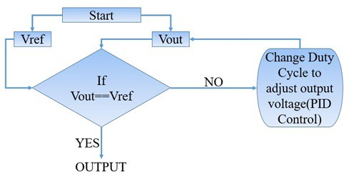
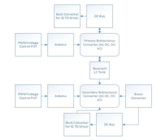
The basic working principle and flow chart of the project is shown in the following Figure 1.
2.1. DC Supply for the Inverter
Input DC supply for converter was to be designed from 0 to 400V and 15A ratings [2]. For this purpose, three components were used.
- Variac transformer for supplying variable AC input to the bridge Rectifier.
- Bridge Rectifier rated at 400V and 15A.
- Smoothing capacitor of 400V and 2200UF.
Variable AC input was fed to the high voltage rectifier. Then rectified pulsating DC was smoothed by using 2200UF, 400V capacitor. Hence re- quired 400V and 15A DC was fed to the inverter [3]. The following figure is showing the high voltage DC supply on the same PCB board contain the high voltage rectifier and 2200uF, 400V rating capacitor.
2.2. Duty Cycle Range
Duty cycle range for the two inverters is 0-0.5 [4]. When primary is fixed at 0.5 secondary is varied from 0 to 0.5, while when secondary is fixed at 0.5 primary is varied from 0 to 0.5 theoretically. Best operation of the novel BSR is at Gain=1 means both duty cycles are 0.5, so BSR is designed near boundary condition [5–9]. The relationship between duty cycle range and the operation modes is shown in the following table.
Table 1: Duty cycle Control: Relationship Between Duty Cycle and Operation Mode
Operaion Mode | Voltage Gain | Duty Cycle | |
Buck | <1 | <0.5 | =0.5 |
Boundary | =1 | =0.5 | =0.5 |
Boost | >1 | >0.5 | <0.5 |
2.3. H-Bridge Inverter
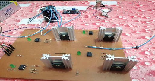
For H-Bridge inverter two complementary PWM signals were generated by microcontroller STM32F407VG. Dead time was included for safe and sound operation of IGBT’s. H-Bridge consists of two legs each containing two IGBTs as switches. Switches in each leg turn on and off complementary to avoid short circuit of High Voltage DC supply and severe damage to circuit. Upper switch of left leg and lower switch of right leg are operated by same signal. Similarly, lower switch of left leg and upper switch of right leg are operated by same signal. When upper switch of left leg and lower switch of right leg are in the ON state then a positive DC voltage of 311V is applied at points a and b. Similarly, when upper switch of right leg and lower switch of left leg are in the ON state then a negative DC voltage of 311V is applied at points a and b. In this sense DC is converted to high frequency 100kHz square wave. In the same way another inverter is operated. The Figure 3 is showing the complete H-Bridge inverter with high voltage DC supply on the same PCB board [10].
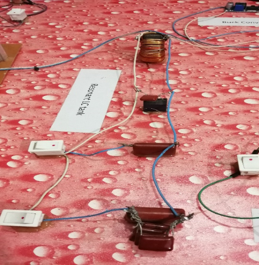
2.4. Resonant Tank
For desired DC to DC converter LC resonant was used to couple the two inverters such that DC side of first inverter was used as input of the whole converter. Then the first inverter AC side was given as input to LC resonant tank for fixed frequency operation. Resonant tank output was given as input to AC side of second inverter [11–19]. DC side of second inverter is used as output of whole converter.
3. Proposed Method
Figure 5 shows the block diagram for the proposed solar system installed with FLC. MPPT [20–25] control in this work is achieved by FLC due to its higher speed.
4. Simulation Results
4.1. Controller Outputs
The Micro-Controller [26], [27] which is used is STM32F407VG. It is based on 32-bit ARM processor. It has max frequency of 168 MHz with 192 kB of RAM and 1MB of ROM. It is selected because it is most versatile in its operation, very flexible to be programmed and has very large number of libraries available [28].
Timers are used to generate the PWM of frequency 110 kHz which can changed acjcording to the resonant frequency of LC-Tank [29]. It is a fixed frequency system that is whatever is the frequency of LC-Tank, it is same throughout the system [30].
The controller is giving four PWM’s, two for each invertor. Each PWM is given to two IGBT’s of different legs of invertor. The two PWM’s given to the invertor are out of phase, center aligned so that two transistors in same ladder are not conducting at once, so that short-circuit is avoided.
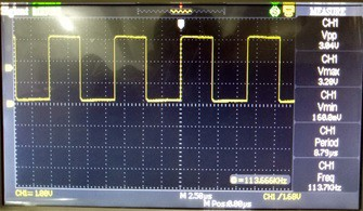
The output of the controller [29], [31–34] or the PWM generated from the micro- controller is shown in the Figure 6.
4.2. Optocoupler Outputs
Optocoupler is a device that is used to isolate the Controller from high power circuit such as in our case the invertor. It uses light to transfer electrical signals to required circuit, hence named Optocoupler. It is taking input from STM microcontroller and is providing signal to the gate of IGBT’s [35–40].
Optocoupler actually serves two purposes, one being isolation and the other providing enough power to gate of IGBT’s. STM outputs are typically 3.3V maximum which is unable to drive gate of IGBT’s as they require typically 15V to conduct.
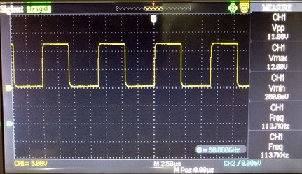
Also, STM pins cannot provide enough current to the gate, so we use Optocoupler. The output obtained from the optocoupler or the response of the optocoupler is shown in the following Figure 7.
4.3. Response of IGBT
IGBT stands for ’insulated-gate bipolar transistor’. It is three terminal device that is mainly used as a switch in an inverter. It combines good properties of Power MOSFET’s and BJT’s. It is used because it has high efficiency, so it can be used in high power circuits and it has fast switching characteristics, so it can be operated at very high frequency. As circuit involve high voltage, high current as well as high frequency, so we select IGBT’s as our switching device.
As the invertor is operating at very high frequency, IGBT’s were not switching off in time due to miller effect. Capacitance effect in IGBT’s be- come dominant at high frequency so some remedies were employed.
Firstly, PCB was made such that it has very small paths between the components so that inductance would not pose the problem in such a condition. So, we made the shortest path between the gate of IGBT and the output terminal of the optocoupler to make the gate signal free from harmonics inclusion.
Secondly, IGBTs were soldered directly on the PCB without using connectors. Also, legs of IGBT’s were made as small as possible.
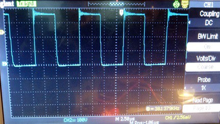
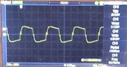
Thirdly, DC power supply inductor was posing the problem, so it was removed as it was main reason behind large ’off-time’ of IGBT. The waveform in the following Figure 8 showing the response of IGBT at high voltage and frequency.

4.4. Inclusion of Dead Time
The dead time is the time in which no part of a H-bridge is turned on. It is used when you have two out of phase PWM signals so that neither the high nor the low side of the H-bridge can be switched-on at once.
If dead time is not included in waveforms, it is very much the possibility that both IGBT’s would turn on, resulting in short-circuit and damaging the DC supply and IGBT’s permanently.
Dead time of 15-20 microseconds is introduce in PWMs with STM controller programming to avoid any kind of short circuiting. The following Figure 9 clearly indicates the dead time included in the two out of phase PWM signals[41].
4.5. LC Tank Response
LC-Tank is an electric circuit, in which both inductance and capacitance are large as compared to resistance which should be ideally zero. Series resonant tank is used as it is better for voltage magnification as is required by the project.
LC-Tank acts as a band pass filter, that can allow certain frequencies and block others. As our inverters are operating at fixed frequency, it is required that this fixed frequency signal contain most of the power and other harmonics of this frequency should be diminished. So, both the invertors frequencies are made equal to the resonant frequency of LC-Tank [42–44]. The Figure 10 shown below is the response of series LC resonant tank when the frequency of the applied PWM signals is equal to the resonant frequency of the LC resonant tank.
5. PWM Control
By controlling the PWM and changing the duty cycle of the generated PWM [45–49], we can operate the inverter in different modes of operation as discussed below.
5.1. Duty Cycle Control
As discussed earlier, the given converter is fixed frequency that means all signals involved have same frequency equal to the resonant frequency of the LC-Tank. Voltage gain of the converter is controlled by the Duty Cycle of signals given to IGBT’s. Let Dp and Ds are Duty Cycles of primary and secondary side upper IGBT’s respectively. Duty Cycle of lower switches are complementary centre-aligned of each of the upper IGBT. Duty Cycle Dp and Ds have no effect on the amount and direction of power. The duty cycle control corresponding to different modes of operation is shown in the following Figure.
5.2. Buck Mode
In Buck mode, voltage gain would be less than one. In this mode, primary side Duty Cycle Dp would always be less than 0.5 and Duty Cycle of secondary side IGBT’s, Ds would be constantly equal to 0.5 [50–52]. Gain can be changed by varying duty cycle Dp in the range from 0 to 0.5 but it would not cross 0.5 threshold.
5.3. Boost Mode
In Boost mode, voltage gain would be greater than one. In this mode, secondary side Duty Cycle Ds would always be less than 0.5 and Duty Cycle of primary IGBTs, Dp would be constantly equal to 0.5. Gain can be changed by varying duty cycle Ds in the range 0 to 0.5 but it would not cross 0.5 threshold.
6. Conclusion
This article has proposed a new serial bidirectional resonance converter (BSR) and its control strategies. The main features of the proposed BSR converter has obtained by theoretical analyses and experiments. Bidirectional regulation of voltage and power flow with a fixed frequency PWM control technique facilitates easily for implementing and controlling the BSR converter. The duty cycles of the primary and secondary switches are used for finding the normalized voltage gain and no change is follow with the direction and amplitude of the transmitted power. Automatic and smooth mode of transition is easily possible due to the simple control of voltage-increasing properties of this BSR converter. In order to get a wide range of voltage in case of bidirectional power conversion application, buck and boost voltage converters has capacity to work for both modes i.e. forward and reverse modes. For getting zero voltage switching of all active switches within full range of load and voltage, auxiliary inductor is used. Soft switches have low circulating energy because of converter working at series resonant frequency.
By combining the all features given in above paragraph, a highly effective bidirectional isolated converter is obtained specifically for micro DC network application. The main characteristics, probability and feasibility of this BSR converter are intended to be evaluated and verified by getting experimental results on a 1.6 kW prototype power with a voltage range of 320V to 480V and a bus voltage of 400V.
Acknowledgment
We are grateful to our teachers and university for the help in data analyzing and manuscript writing.
- J. M. Burdio et al., “Asymmetrical voltage-cancellation control for full-bridge series resonant inverters,” IEEE transactions on power electronics, vol. 19, no. 2, pp. 461–469, 2004. DOI: 10.1109/TPEL.2003.823250
- H.-S. Choi, “Design consideration of half-bridge LLC resonant converter,” Journal of power electronics, vol. 7, no. 1, pp. 13–20, 2007.
- Y.-C. Chuang, Y.-L. Ke, “A novel high-efficiency battery charger with a buck zero-voltage-switching resonant converter,” IEEE Transactions on Energy Conversion, vol. 22, no. 4, pp. 848–854, 2007. DOI: 10.1109/TEC.2006.882416
- L. Corradini et al., “Minimum current operation of bidirectional dual-bridge series resonant DC/DC converters,” IEEE Transactions on Power Electronics, vol. 27, no. 7, pp. 3266–3276, 2011. DOI: 10.1109/TPEL.2011.2181421
- D.-Y. Jung et al., “Soft-switching bidirectional DC/DC converter with a LC series resonant circuit,” IEEE Transactions on Power Electronics, vol. 28, no. 4, pp. 1680–1690, 2012. DOI: 10.1109/TPEL.2012.2208765
- H. Kifune, Y. Hatanaka, M. Nakaoka, “Cost effective phase shifted pulse modulation soft switching high frequency inverter for induction heating applications,” IEE Proceedings-Electric Power Applications, vol. 151, no. 1, pp. 19–25, 2004. DOI: 10.1049/ip-epa:20040085
- H. Krishnaswami, N. Mohan, “Three-port series-resonant DC–DC converter to interface renewable energy sources with bidirectional load and energy storage ports,” IEEE Transactions on Power Electronics, vol. 24, no. 10, pp. 2289–2297, 2009. DOI: 10.1109/TPEL.2009.2022756
- Y.-S. Kwon, S.-B. Yoo, D.-S. Hyun, “Half-bridge series resonant inverter for induction heating applications with load-adaptive PFM control strategy,” APEC’99. Fourteenth Annual Applied Power Electronics Conference and Exposition. 1999 Conference Proceedings (Cat. No. 99CH36285), vol. 1, pp. 575–581, 1999. DOI: 10.1109/APEC.1999.749738
- J.-S. Lai, “Resonant snubber-based soft-switching inverters for electric propulsion drives,” IEEE Transactions on Industrial Electronics, vol. 44, no. 1, pp. 71–80, 1997. DOI: 10.1109/41.557501
- E. J. Dede et al., “Soft switching series resonant converter for induction heating applications,” Proceedings of 1995 International Conference on Power Electronics and Drive Systems. PEDS 95, pp. 689–693, 1995.
- M. A. Akbar et al., “A robust framework for cloud‐based software development outsourcing factors using analytical hierarchy process,” Journal of Software: Evolution and Process, vol. 33, no. 2, pp. e2275, 2021.
- M. A. Akbar et al., “A fuzzy analytical hierarchy process to prioritize the success factors of requirement change management in global software development,” Journal of Software: Evolution and Process, vol. 33, no. 2, pp. e2292, 2021.
- M. A. Akbar et al., “Improving the quality of software development process by introducing a new methodology–AZ-model,” IEEE Access, vol. 6, pp. 4811–4823, 2017.
- M. A. Akbar et al., “Investigation of Project Administration related challenging factors of Requirements Change Management in global software development: A systematic literature review,” 2018 International Conference on Computing, Electronic and Electrical Engineering (ICE Cube), pp. 1–7, 2018.
- A. Mateen, M. Azeem, M. Shafiq, “AZ model for software development,” arXiv preprint arXiv:1612.08811, 2016.
- J. Sang et al., “Joint image compression and encryption using IWT with SPIHT, Kd-tree and chaotic maps,” Applied Sciences, vol. 8, no. 10, pp. 1963, 2018.
- A. Mateen, M. A. Akbar, “Estimating software reliability in maintenance phase through ann and statistics,” arXiv preprint arXiv:1605.00774, 2016.
- A. Mateen et al., “Comparative analysis of wireless sensor networks with wireless multimedia sensor networks,” 2017 IEEE International Conference on Power, Control, Signals and Instrumentation Engineering (ICPCSI), pp. 80–83, 2017.
- A. Mateen, K. Abbas, M. A. Akbar, “Robust approaches, techniques and tools for requirement engineering in agile development,” 2017 IEEE International Conference on Power, Control, Signals and Instrumentation Engineering (ICPCSI), pp. 100–103, 2017.
- M. Mateen, J. Wen, M. A. A. Nasrullah, “The Role of Hyperspectral Imaging: A Literature,” .
- S. Akram, M. Shafiq, M. A. Akbar, “Automated risk analysis model for software development enhancement,” International Journal of Multidisciplinary Sciences and Engineering, vol. 7, no. 8, pp. 23–27, 2016.
- N. Nasrullah et al., “Reversible data hiding in compressed and encrypted images by using Kd-tree,” Multimedia Tools and Applications, vol. 78, no. 13, pp. 17535–17554, 2019.
- J. Ahmad et al., “The deep neural network based classification of fingers pattern using electromyography,” 2018 2nd IEEE Advanced Information Management, Communicates, Electronic and Automation Control Conference (IMCEC), pp. 455–461, 2018.
- M. A. Akbar et al., “AZ-Model of software requirements change management in global software development,” 2018 International Conference on Computing, Electronic and Electrical Engineering (ICE Cube), pp. 1–6, 2018.
- A. A. Khan, M. A. Akbar, “Systematic literature review and empirical investigation of motivators for requirements change management process in global software development,” Journal of Software: Evolution and Process, vol. 32, no. 4, pp. e2242, 2020.
- M. A. Akbar et al., “Organization type and size based identification of requirements change management challenges in global software development,” IEEE Access, vol. 8, pp. 94089–94111, 2020.
- M. A. Akbar et al., “Prioritizing Management Success Factors in Offshore Software Development,” Arabian Journal for Science and Engineering, vol. 45, no. 12, pp. 10163–10184, 2020.
- G. Hua et al., “Novel zero-current-transition PWM converters,” Proceedings of IEEE Power Electronics Specialist Conference-PESC’93, pp. 538–544, 1993.
- M. A. Akbar et al., “Towards successful agile development process in software outsourcing environment: a systematic literature review,” International Journal of Business Innovation and Research, vol. 23, no. 2, pp. 141–167, 2020.
- M. A. Akbar et al., “An empirical study investigation of task allocation process barriers in the context of offshore software development outsourcing: An organization size based analysis,” International Journal of Computing and Digital Systems, vol. 8, no. 04, pp. 343–350, 2019.
- M. A. Akbar et al., “Multicriteria decision making taxonomy of cloud-based global software development motivators,” IEEE Access, vol. 8, pp. 185290–185310, 2020.
- M. A. Akbar et al., “Requirement change management challenges in GSD: An analytical hierarchy process approach,” Journal of Software: Evolution and Process, vol. 32, no. 7, pp. e2246, 2020.
- M. A. Akbar et al., “Prioritization of global software requirements’ engineering barriers: An analytical hierarchy process,” IET Software, vol. 15, no. 4, pp. 277–291, 2021.
- M. A. Akbar et al., “Success factors influencing requirements change management process in global software development,” Journal of Computer Languages, vol. 51, pp. 112–130, 2019.
- M. T. Riaz et al., “A wireless controlled intelligent healthcare system for diplegia patients,” Mathematical Biosciences and Engineering, vol. 19, no. 1, pp. 456–472, 2022.
- M. T. Riaz et al., “Wireless android based home automation system,” Adv. Sci. Technol. Eng. Syst. J, vol. 2, no. 1, pp. 234–239, 2017.
- H. A. Javaid et al., “Classification of Hand Movements Using MYO Armband on an Embedded Platform,” Electronics, vol. 10, no. 11, pp. 1322, 2021.
- M. T. Riaz et al., “The Intelligent Transportation Systems with Advanced Technology of Sensor and Network,” 2021 International Conference on Computing, Electronic and Electrical Engineering (ICE Cube), pp. 1–6, 2021.
- M. T. Riaz et al., “Design and Experimental Validation of a Small-Scale Prototype Active Aerostatic Thrust Bearing,” 2021 International Conference on Computing, Electronic and Electrical Engineering (ICE Cube), pp. 1–6, 2021.
- M. T. Riaz et al., “Wireless model for high voltage Direct Current measurement using Hall sensor,” 2021 International Bhurban Conference on Applied Sciences and Technologies (IBCAST), pp. 642–647, 2021.
- R. W. A. A. De Doncker, D. M. Divan, M. H. Kheraluwala, “A three-phase soft-switched high-power-density DC/DC converter for high-power applications,” IEEE transactions on industry applications, vol. 27, no. 1, pp. 63–73, 1991.
- M. Idrees et al., “Fuzzy logic based calculation and analysis of health index for power transformer installed in grid stations,” 2019 international symposium on recent advances in electrical engineering (RAEE), vol. 4, pp. 1–6, 2019.
- H. A. Raza et al., “Analysis the effect of 500kv High-Voltage Power Transmission Line on the Output Efficiency of Solar-Panels,” 2019 International Conference on Electrical, Communication, and Computer Engineering (ICECCE), pp. 1–6, 2019, doi:10.1109/ICECCE47252.2019.8940803.
- L. Hanwu et al., “Regularity of Current Dispersal in Different Kinds of Grounding Electrode,” 2018 IEEE International Conference on High Voltage Engineering and Application (ICHVE), pp. 1–4, 2018, doi:10.1109/ICHVE.2018.8642240.
- J.-J. Lee et al., “Dual series-resonant active-clamp converter,” IEEE Transactions on Industrial Electronics, vol. 55, no. 2, pp. 699–710, 2008.
- R. Laouamer et al., “A multi-resonant converter for non-contact charging with electromagnetic coupling,” Proceedings of the IECON’97 23rd International Conference on Industrial Electronics, Control, and Instrumentation (Cat. No. 97CH36066), vol. 2, pp. 792–797, 1997.
- X. Li, A. K. S. Bhat, “Analysis and design of high-frequency isolated dual-bridge series resonant DC/DC converter,” IEEE Transactions on Power Electronics, vol. 25, no. 4, pp. 850–862, 2009.
- B. Lu et al., “Optimal design methodology for LLC resonant converter,” Twenty-First Annual IEEE Applied Power Electronics Conference and Exposition, 2006. APEC’06., pp. 6-pp, 2006.
- H. Wu et al., “Bidirectional soft-switching series-resonant converter with simple PWM control and load-independent voltage-gain characteristics for energy storage system in DC microgrids,” IEEE Journal of Emerging and Selected Topics in Power Electronics, vol. 5, no. 3, pp. 995–1007, 2017.
- M. T. Riaz et al., “Design of a Free Energy Generator using Gravity Wheel & Dynamo,” 2021 4th International Conference on Energy Conservation and Efficiency (ICECE), pp. 1–5, 2021.
- M. T. Riaz et al., “Analysis and Evaluating the Effect of Harmonic Distortion Levels in Industry,” 2021 4th International Conference on Energy Conservation and Efficiency (ICECE), pp. 1–7, 2021, doi:10.1109/ICECE51984.2021.9406283.
- M. T. Riaz et al., “Steady state analysis of HVDC transmission system based on MATLAB/SIMULINK,” 2019 International Conference on Electrical, Communication, and Computer Engineering (ICECCE), pp. 1–6, 2019.