Images Compression using Combined Scheme of Transform Coding

(This article belongs to the Special Issue on Special Issue on Multidisciplinary Sciences and Advanced Technology (SI-MSAT 2022) and the Section Interdisciplinary Applications – Computer Science (IAC))
Export Citations
Cite
Ahmed, Z. J. , George, L. E. and Hadi, R. A. (2022). Images Compression using Combined Scheme of Transform Coding. Journal of Engineering Research and Sciences, 1(9), 8–14. https://doi.org/10.55708/js0109002
Zainab Jawad Ahmed, Loay Edwar George and Raad Ahmed Hadi. "Images Compression using Combined Scheme of Transform Coding." Journal of Engineering Research and Sciences 1, no. 9 (September 2022): 8–14. https://doi.org/10.55708/js0109002
Z.J. Ahmed, L.E. George and R.A. Hadi, "Images Compression using Combined Scheme of Transform Coding," Journal of Engineering Research and Sciences, vol. 1, no. 9, pp. 8–14, Sep. 2022, doi: 10.55708/js0109002.
Some problems want to be solved in image compression to make the process workable and more efficient. Much work had been done in the field of lossy image compression based on wavelet and Discrete Cosine Transform (DCT). In this paper, an efficient image compression scheme is proposed, based on a common encoding transform scheme; It consists of the following steps: 1) bi-orthogonal (tab 9/7) wavelet transform to split the image data into sub-bands, 2) DCT to de-correlate the data, 3) the combined transform stage's output is subjected to scalar quantization before being mapped to positive, 4) and LZW encoding to produce the compressed data. The peak signal-to-noise (PSNR), compression ratio (CR), and compression gain (CG) measures were used to perform a comparative analysis of the performance of the whole system. Several image test samples were used to test the performance behavior. The simulation results show the efficiency of these combined transformations when LZW is used in the field of data compression. Compression outcomes are encouraging and display a significant reduction in image file size at good resolution.
1. Introduction
Images demand a lot of storage space, a lot of transmission bandwidth, and a lot of transmission time since they contain a lot of information. To reduce the number of bits required to represent an entity to match the actual situation, it is beneficial to compress the image by keeping only the information necessary to rebuild the image [1]. Data compression is a method for reducing redundant data representations, which lowers the need for data storage and, in turn, lowers communication costs. Increasing the capacity and transmission bandwidth of the storage media is comparable to decreasing the amount of storage required. Therefore, creating effective compression methods will remain a design problem for advanced multimedia applications and communication systems. Redundancy and information are combined to represent data and to appropriately evaluate the meaning or purpose of the data, information is a part of data and must be permanently kept in its original form [2]. Redundancy is the part of the data that can be eliminated when it is not required or reinserted to help analyze the data when it is required. To produce the original data in its original form, the redundancy is typically reinserted. Data compression is the practice of reducing data redundancy. Decompression of the data is the process of reducing redundancy in data representation so that it can later be reinserted to recover the original data [3, 4].
The goal of this work is to develop a color image compression system that is effective and efficient and is based on wavelet transformation and DCT. The image is split into four subbands where the wavelet processing is applied. For a specified number, the wavelet transform is repeated. After then, each subband is split up into a set of blocks, and each block is subjected to a DCT transformation. For each block, adaptive scalar quantization was used. By taking advantage of the fact that these high-frequency blocks can be treated separately from low frequencies to produce better compression, the level of the quantization values varies according to the block feature, whether it is high frequency detailed blocks or low frequency correlated blocks. LZW is used to compress the data in the end. Compression ratio (CR), peak signal to noise ratio (PSNR), compression gain (CG), and encoding and decoding times are frequently used to estimate an image compression system’s efficiency.
2. Literature Review
Review of the compression methods using the DCT section (2.1) and wavelet transformation section (2.2).
2.1. Image Compression with DCT
In [5] the authors suggested image compression strategies employing the DCT method with various blocks and quantization methods for lowering the blocking artifacts in reconstruction images. The maximum image dimension is divided into a maximum block size in the suggested approach, which then compresses the image. The proposed method divides the image into blocks (4×4, 8×8, 16×16, and 32×32. A PSNR score is produced using different quantization matrices to compare the performance of the original and reconstructed pictures. Based on the data, it can be concluded that the restored image becomes deformed as the quantization matrix’s maximum value lowers. According to [6], the RGB to YCbCr color transformation process is used to carry out the proposed compression technique. Second, blocks are divided into the edge and non-edge blocks using canny edge detection. Each Y, Cb, and Cr color variable is compressed, quantized, and coded by the (DCT) method using adaptive arithmetic coding. The fast JPEG image compression technique based on DCT was proposed by [7]. The algorithm describes how to encode and decode images for JPEG. The image’s encoding component can use JEPG to process images in the BMP format and compress them into binary files for real-time storage. The related decoding program can decompress the image. Additionally, the JPEG format can be used to encode a static image, and the color RBG of the JPEG image can be transformed into brightness y, Chroma Cr, and CB, which can efficiently minimize Chroma data and achieve compression. This is possible since human vision is not sensitive to Chroma.
2.2. Image Compression with Wavelet
To produce better-decompressed image output than the compression approach DWT+DCT [8], the authors introduced the Hybrid Integer Wavelet Transform (IWT) and Discrete Cosine Transform (DCT). In comparison to DWT-based and hybrid DWT DCT-based image compression approaches, the proposed combination IWT + DCT-based compression methodology decreases fractional loss and hence offers a higher image quality of the decompressed image on high compression ratios. According to [9] the proposed approach begins by separating the image into sub-images and uses a high-level discrete wavelet transform, multiple levels of compression are used. With high-quality reconstructed images, the Huffman code with non-uniform Quantizer has also been employed to reduce the compression data rate. The suggested method’s encouraging simulation results met the most important criteria, which are represented by the great image quality and a high image compression ratio. As an illustration, the PSNR and compression ratio (CR) of the Lena image achieved by the proposed approach simulation were 42.4094 dB and 47.5435, respectively. In [10] for effective and economical image compression, the discrete wavelet transforms (DWT) based on HAAR wavelets is used. Since the coefficient of HAAR DWT is either 1, or -1, it offers a simple method of compression. The temporal and frequency analysis employs wavelet transforms. After three levels of decomposition, a greater compression ratio is obtained in this paper. By taking into account both the image’s overall quality and specific visual elements, the results are encouraging.
3. Image System Model
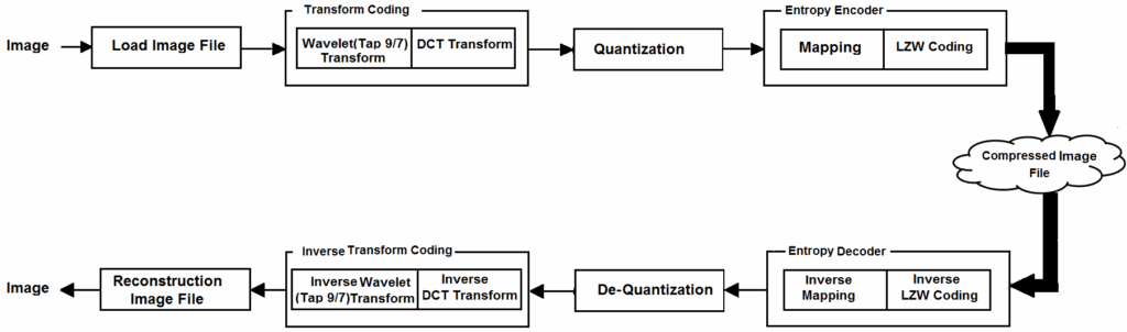
Image compression algorithms have been used with four connected stages in the suggested compression system to produce a high compression ratio with high image quality. A. Load image file, B. Transform Coding, C. Quantization, and D. Entropy Encoder are the steps in this process. To acquire the image data, the load image file is first used. Second, an appropriate transform (DWT and DCT) is done. Thirdly, the results are subjected to a scalar quantization operation to eliminate any psycho-visual redundancies that may still exist. It should be noted that the quantization is performed just once after applying both transforms. After mapping quantization values to positive numbers, LZW coding is used to code the data. Figure 1 indicates the structure of the system model; the following sections go into more depth about each stage of the system.
3.1. Load Image Data
The essential information of the image, as well as the data for the three red, green, and blue bands, are obtained by reading the image data.
3.2. Transformation Coding
In this stage, the image data is converted from the time domain to the frequency domain using the bi-orthogonal (Tap 9/7) wavelet transform and Discrete Cosine Transform (DCT).
- Discrete Cosine Transform (DCT): The choice of this method as the JPEG standard has made it the most widely used image compression approach over the past few years [11]. A lossy compression technique called discrete cosine transform transforms NxN blocks from the spatial domain to the DCT domain. Concerning the visual quality of the image, the discrete cosine transform (DCT) assists in dividing the image into components (or spectral sub-bands) of varying relevance [12].
- Wavelet Transform: The wavelet transform has emerged as a key technique for image compression. Wavelet-based coding significantly improves image quality at high compression ratios, primarily because wavelet transforms have higher energy compaction properties [13]. The wavelet transform procedure is a straightforward idea. To replace the original transformed image, four new sub-images are created. Each sub-image is one-fourth the size of the original [14].
3.3. Quantization
Because it uses fewer bits to hold the transformed coefficient, quantization is regarded as the main source of the compression process. The quantizer reduces the accuracy of the transformed coefficient values because quantization is a many-to-one mapping [14]. In the quantization process, each coefficient in the fixed block DCT array is divided by a corresponding element Qs that is generated adaptively using the equation [15]:
$$\text{DCT}_Q(x, y) = \text{round} \left( \frac{\text{DCT}(x, y)}{Q_s} \right) \tag{1}$$
Where the Qs is calculated by the following equations:
$$Q_s = \begin{cases}
Q_0 & \text{for DC coefficient} \\
Q_1 \times \left(1 + \alpha(u,v)\right) & \text{for AC coefficients}
\end{cases} \tag{2}$$
3.4. Entropy Encoder
Use the right set of entropy encoders to effectively reduce any statistical redundancy that may be present in the resulting converted data. The mapping to positive and LZW are utilized at this step.
- Mapping to positive: Each positive value is transformed into an even number in the mapping stage, whereas each negative element’s value is transformed into a positive odd number. The straightforward mapping equation is shown below [16] can be utilized to apply this conversion:
$$\mathbf{m}_{\text{out}}(i) = \begin{cases}
2V(i) & \text{if } V(i) \geq 0 \\
-2V(i) + 1 & \text{if } V(i) < 0
\end{cases} \tag{3}$$
- Lempel Ziv Welch (LZW): Conceptually, LZW encoding is quite straightforward. The goal is to generate a dictionary (a table) of the strings used during the communication session at the beginning of the coding process. To decrease the amount of data communicated, previously encountered strings might be substituted by their index in the dictionary if both the sender and the receiver have a copy of it [17].
4. Proposed Compression System
One of the most helpful uses of this system is transform-based compression, which enables the effective transmission, storage, and display of images that would otherwise be impossible. The processes that the image goes through to be compressed are as follows:
- Red, Green, and Blue band values are calculated by reading the color image.
- Each band is subjected to the bi-orthogonal 9/7 wavelet transformation, which separates the band data into the (LL, LH, HL, HH) coefficients.
- Each subband has a certain type of image data. Depending on the value of the parameter (i.e., Npass) for the number of wavelet transform passes, which the user has previously defined, the transform process may be repeated.
- Creating a set of pointers that denote the beginning (be) and ending (ed) of each subband of the wavelet coefficients.
- Each subband’s wavelet coefficients are divided into blocks of (N×N). After that, each block is handled independently until the final one.
- Using the DCT transform, the data of each block (i.e., each subband of the wavelet coefficients) is independently deconstructed.
- Because the results of wavelet-DCT coefficients are real-valued, they must first be quantized to increase compression. Equations [1, 2] are used to apply uniform scalar quantization to the converted wavelet-DCT coefficients of each created block.
- To simplify the coding procedure for the following phase, equation [3] is used to map the sequence elements to be positive values.
- Encode the mapping data using the LZW compression algorithm to obtain compressed data.
4.1. Decoding
Decompression works in reverse of the steps involved in image compression and aims to restore the original image without compression. Where it contains LZW decoding, mapping to negative, dequantization, inverse DCT for each block, inverse wavelet transform, and reconstructed image data. The decoding method is shown in Figure 1.
5. Results
Various standard images were selected; all the images are square color scale images of size 256×256 pixels of 24 bit/per pixel shown in Figure 2. The effectiveness of the following system parameters was investigated:
- Npass the number of wavelets passes, with range {2, 3, 4, 5}.
- Q0 is the quantization parameter for DC coefficients, with range {1, 2,.., 20}.
- Q1 is the quantization parameter for AC coefficients, with range {10, 11,.., 30}.
- Alpha (𝛼) is the scaling factor for AC coefficients, with range {0.01, 0.02, .., 0.1}.
- Blks the block size, with range {4×4, 8×8, 16×16}.
The values of these variables were tested on the image, and the values of the compression ratio, compression gain, and the quality of the resulting image were changed. The results of these tests are shown in the Table 1. The proposed system in the Table 2, Table 3, Table 4, Table 5, and Table 6 was tested for the impact of the parameters. Increasing the values of these variables leads to an increase in the compression ratio and compression gain with a decrease in image quality. The PSNR value verifies that the compression and reconstruction of the original image are better even at level 2 of the wavelet transform, Q0=1, Q1=20, 𝛼=0.06, and Blks=8×8. The results were also compared between the time of compression and the time of decompression of Lena’s image in the Table 7, and the table showed good results.
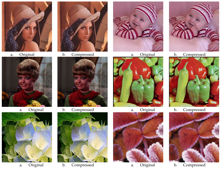
Table 1: The Control Parameters’ Default Values with the Best PSNR and CR
Samples | Npass | Q0 | Q1 | 𝛼 | CR | CG | PSNR |
Lena | 2 | 11 | 20 | 0.06 | 22.04 | 95.56 | 32.22 |
Child | 2 | 23 | 21 | 0.06 | 15.48 | 94.83 | 32.03 |
Girl | 2 | 24 | 20 | 0.06 | 19.60 | 95.18 | 32.15 |
Pepper | 2 | 25 | 17 | 0.06 | 13.28 | 92.22 | 32.08 |
Flowers | 2 | 25 | 17 | 0.06 | 16.97 | 93.31 | 32.19 |
Winter | 2 | 18 | 21 | 0.06 | 18.84 | 95.15 | 32.00 |
Table 2: The effect of Npass on CR and PSNR
Npass | CR | CG | PSNR |
2 | 22.039 | 95.56529 | 32.225 |
3 | 23.639 | 95.92692 | 30.269 |
4 | 24.304 | 96.06018 | 29.057 |
5 | 24.544 | 96.10596 | 28.168 |
Table 3: The Effect of Q0 on CR and PSNR
Q0 | CR | CG | PSNR |
| Q0 | CR | CG | PSNR |
1 | 12.1 | 94.87 | 35.93 | 11 | 22.0 | 95.56 | 32.22 | |
2 | 13.2 | 95.06 | 35.63 | 12 | 23.1 | 95.57 | 31.92 | |
3 | 14.2 | 95.19 | 35.13 | 13 | 24.2 | 95.59 | 31.52 | |
4 | 15.3 | 95.28 | 34.83 | 14 | 25.2 | 95.60 | 31.01 | |
5 | 16.3 | 95.35 | 34.23 | 15 | 26.3 | 95.62 | 30.81 | |
6 | 17.4 | 95.41 | 33.93 | 16 | 27.3 | 95.63 | 30.51 | |
7 | 18.4 | 95.45 | 33.63 | 17 | 28.4 | 95.64 | 30.10 | |
8 | 19.4 | 95.48 | 33.22 | 18 | 29.4 | 95.64 | 29.80 | |
9 | 20.4 | 95.51 | 32.93 | 19 | 30.4 | 95.64 | 29.50 | |
10 | 21.9 | 95.54 | 32.72 | 20 | 31.4 | 95.65 | 29.09 |
Table 4: The effect of Q1 on CR and PSNR
Q1 | CR | CG | PSNR | Q1 | CR | CG | PSNR | ||||||||
10 | 15.2 | 92.15 | 36.67 | 21 | 22.8 | 95.75 | 31.95 | ||||||||
11 | 15.9 | 92.70 | 36.04 | 22 | 23.6 | 95.92 | 31.69 | ||||||||
12 | 16.7 | 93.16 | 35.45 | 23 | 24.4 | 96.08 | 31.44 | ||||||||
13 | 17.5 | 93.58 | 34.91 | 24 | 25.1 | 96.21 | 31.20 | ||||||||
14 | 18.3 | 93.96 | 34.45 | 25 | 25.9 | 96.35 | 30.98 | ||||||||
15 | 19.0 | 94.30 | 34.02 | 26 | 26.7 | 96.47 | 30.77 | ||||||||
16 | 19.8 | 94.59 | 33.60 | 27 | 27.5 | 96.59 | 30.56 | ||||||||
17 | 20.6 | 94.88 | 33.23 | 28 | 28.3 | 96.70 | 30.37 | ||||||||
18 | 21.4 | 95.12 | 32.87 | 29 | 28.9 | 96.80 | 30.12 | ||||||||
19 | 21.8 | 95.35 | 32.53 | 30 | 29.6 | 96.90 | 30.02 | ||||||||
20 | 22.0 | 95.56 | 32.22 | ||||||||||||
Table 5: The Effect of Alpha on CR and PSNR
𝛼 | CR | CG | PSNR | 𝛼 | CR | CG | PSNR | |
0.01 | 17.170 | 94.35 | 34.04 | 0.06 | 22.0 | 95.56 | 32.2 | |
0.02 | 18.943 | 94.64 | 33.64 | 0.07 | 23.8 | 95.73 | 31.7 | |
0.03 | 19.755 | 94.92 | 33.26 | 0.08 | 24.5 | 95.90 | 31.5 | |
0.04 | 20.536 | 95.16 | 32.89 | 0.09 | 25.2 | 96.03 | 31.1 | |
0.05 | 21.254 | 95.36 | 32.55 | 0.1 | 26.9 | 96.17 | 31.1 |
Table 6: The Effect of Block Size on CR and PSNR
Blks | CR | CG | PSNR |
4×4 | 16.939 | 94.64518 | 34.027 |
8×8 | 22.039 | 95.56529 | 32.225 |
16×16 | 24.103 | 96.68121 | 29.794 |
Table 7: The Encoding and Decoding Time in Second
Samples | ET | DT |
Lena | 0.209 | 0.12 |
Child | 0.218 | 0.182 |
Girl | 0.239 | 0.140 |
Pepper | 0.233 | 0.170 |
Flowers | 0.221 | 0.123 |
Winter | 0.230 | 0.110 |
Based on PSNR and CR criteria, the suggested method’s performance metrics for Lena’s image have been contrasted with the situation of artworks in Table 8. When compared to earlier work, the results indicated a good compression ratio.
Table 8: Comparison with Previous Works
Article | Method | CR | PSNR |
[15] | 1. The image compression using; DCT and bi-orthogonal (tap-9/7) wavelet transform. 2. Compression using LZW coding. 3. Comparing the results between them. | 20.18 | 32.02 |
[18] | 1. The image is subdivided into blocks. 2. One-D DCT is performed for each block. 3. An adaptive scalar quantization is performed. 4. The zigzag scanning. 5. An adaptive shift encoder is utilized. | 12.8 | 32.22 |
[19] | 1. Fast DCT is used. 2. Removed most of the zeros and keeps their positions in a transformed block. 3. Arithmetic coding is performed rather than Huffman coding. | 20.49 | 36.468 |
[20] | 1. Each block of the image is represented with a first- or second-order two-dimensional polynomial. 2. The encoded block size of the image is variable. 3. The polynomial order and the encoded block size are determined dynamically depending on the value of a threshold. 4. A prefix code of two bits is used to differentiate the encoding states. 5. Uniform quantization is applied to the coefficient matrix. | 6.9977 | 31.0126 |
Proposed method | 22.039 | 32.225 | |
At the end, the previous work [15] which relied on performing the wavelet transform and DCT transformation separately on the images, then compressing using LZW and comparing the results, unlike this work, which relied on the wavelet transformation procedure, then taking the resulting subbands and performing the DCT transformation on them and then LZW compressing. This work was able to progress on the previous work in terms of compression ratio with the same image quality 32db, but in terms of time only, it was close to the time of the previous work.
6. Conclusion
This study used wavelet, DCT, and LZW approaches to create computationally efficient and effective lossy image compression algorithms. Where the results showed that in the previous research [15] the compression ratio is 20.18, which depended on the image compression using; DCT and bi-orthogonal (tap-9/7) wavelet transform, then compression using LZW coding. While in the current research, the compression ratio shows progress reached to 22.039. Therefore, the suggested approach quickly compresses the image. Regarding the quality of the reconstructed images and the preservation of significant image elements, encouraging findings were observed. The project involves applying the bi-orthogonal 9/7 wavelet transform compression, followed by using the DCT approach and comparing results across different input images. In terms of time compression and decompression, the effort has shown positive results. It demonstrated how changing the values of the parameters affects both the compression ratio, compression gain, and the image quality, because increasing these values leads to lowers the image quality while raising the compression ratio and gain. When compared to a variety of earlier works, the work demonstrated good compression results.
- G. Xin, P. Fan, “A lossless compression method for multi‑component medical images based on big data mining,” Scientific Reports, vol.11, no.12372, pp.1-11, June 2021, DOI: 10.1038/s41598-021-91920-x.
- N. Lata, “Image Compressions Techniques: A Review,” Journal of Emerging Technologies and Innovative Research (JETIR), vol.6, no.3, pp. 368-375, March 2019.
- S. Mathew, S. Sebastian, “Comparison of Jpeg Compression Technique with Shape Adaptive DCT Technique (SA-DCT),” International Journal of Advance Research in Computer Science and Management Studies, vol. 3, no.4, pp.412-417, April 2015.
- T. Acharya, P.-S. Tsai, JPEG2000 Standard for Image Compression: Concepts, Algorithms and VLSI Architectures, Wiley, October 2004.
- S.S.Pandey et al., “Block wise image compression and block reduced artifacts using discrete cosine transform,” International Journal of Scientific and Research Publications, vol.5, no.3, pp.1-10, March 2015.
- W.M. Abd-Elhafiez, E. O. Abdel-Rahman, “New Efficient Method for Coding Color Images,” Applied Mathematics and Information Sciences an International Journal, vol.10, no.1, pp.357–361, January 2016, doi: 10.18576/amis/100138.
- W. Xiao et al., “A Fast JPEG Image Compression Algorithm Based on DCT,” IEEE International Conference on Smart Cloud, USA, pp.106-110, November 2020, doi: 10.1109/SmartCloud49737.2020.00028.
- S. L. Agrwal et al. , “Improved image compression technique using IWT-DCT transformation,” 2nd International Conference on Next Generation Computing Technologies (NGCT), IEEE, Dehradun, pp. 683–686, October 2016, doi: 10.1109/NGCT.2016.7877499.
- R. K. Gaber et al., “Image Compression Using High Level Wavelet Transformer with Non-Uniform Quantizer and Different Levels Huffman Codes,” IOP Conf. Series: Materials Science and Engineering, vol. 765, no.1:012072, pp.1-13, March 2020, doi:10.1088/1757-899X/765/1/012072.
- H. Kanagaraj, V. Muneeswaran, “Image compression using HAAR discrete wavelet transform,” 5th International Conference on Devices, Circuits and Systems (ICDCS), IEEE, India, March 2020, doi: 10.1109/ICDCS48716.2020.243596.
- N. Ahmed et al., “Discrete cosine transform,” IEEE transactions on Computers, vol. C-23, no.1, pp. 90-93, 1974, doi: 10.1109/T-C.1974.223784.
- F. Alfiah et al., “Discrete Cosine Transform DCT Methods on Compression RGB and Grayscale image,” International Journal of Computer Techniques, vol. 4, no.60, pp. 24, 29, December, 2017.
- S. V Konlade, V.S Gangwani, “Color Image Compression Using DCT & DWT,” International Journal of Scientific Development and Research (IJSDR) , vol. 2, no.6, pp. 258-263, June 2017.
- A. Kurniawa et al., “Implementation of Image Compression Using Discrete Cosine Transform (DCT) and Discrete Wavelet Transform (DWT),” International Journal of Applied Engineering Research, vol. 12, no.23, pp.13951-13958, 2017.
- Z. J. Ahmed, Loay E. George, “A Comparative Study Using LZW with Wavelet or DCT for Compressing Color Images,” Third International Conference on Advanced Science and Engineering (ICOASE2020), Iraq, pp. 53-58, 2020, doi: 10.1109/ICOASE51841.2020.9436622.
- Z. J. Ahmed, L. E. George, “Lightweight Image Compression Using Polynomial and Transform Coding,” V. International Scientific Congress of Pure, Applied and Technological Sciences (Minar Congress), Rimar Academy Turkey, pp.172-192, 2022.
- P.Ravi, A.Ashokkumar, “A Study of Various Data Compression Techniques,” International Journal of Computer Science and Communication, vol. 6, no.2, pp. 1-8, 2015.
- E. Kh. Hassan et al., “Color Image Compression Based on DCT, Differential Pulse Coding Modulation, and Adaptive Shift Coding,” Journal of Theoretical and Applied Information Technology, vol.96, no.11, pp. 3160-3171, June 2018.
- A.A. Hussain et al., “Developed JPEG Algorithm Applied in Image Compression,” 2nd International Scientific Conference of Al-Ayen University (ISCAU-2020) IOP Publishing, pp.1-17, November 2020, doi: 10.1088/1757-899X/928/3/032006.
- Sh. Othman et al., “Lossy Compression using Adaptive Polynomial Image Encoding,” Advances in Electrical and Computer Engineering, vol. 21, no.1, pp.91-98, February 2021, doi: 10.4316/AECE.2021.01010.
No related articles were found.