CANClassify: Automated Decoding and Labeling of CAN Bus Signals

(This article belongs to the Special Issue on Special Issue on Multidisciplinary Sciences and Advanced Technology (SI-MSAT 2022) and the Section Interdisciplinary Applications – Computer Science (IAC))
Export Citations
Cite
Ngo, P. , Sprinkle, J. and Bhadani, R. (2022). CANClassify: Automated Decoding and Labeling of CAN Bus Signals. Journal of Engineering Research and Sciences, 1(10), 5–12. https://doi.org/10.55708/js0110002
Paul Ngo, Jonathan Sprinkle and Rahul Bhadani. "CANClassify: Automated Decoding and Labeling of CAN Bus Signals." Journal of Engineering Research and Sciences 1, no. 10 (October 2022): 5–12. https://doi.org/10.55708/js0110002
P. Ngo, J. Sprinkle and R. Bhadani, "CANClassify: Automated Decoding and Labeling of CAN Bus Signals," Journal of Engineering Research and Sciences, vol. 1, no. 10, pp. 5–12, Oct. 2022, doi: 10.55708/js0110002.
Controller Area Network (CAN) bus data is used on most vehicles today to report and communicate sensor data. However, this data is generally encoded and is not directly interpretable by simply viewing the raw data on the bus. However, it is possible to decode CAN bus data and reverse engineer the encodings by leveraging knowledge about how signals are encoded and using independently recorded ground-truth signal values for correlation. While methods exist to support the decoding of possible signals, these methods often require additional manual work to label the function of each signal. In this paper, we present CANClassify — a method that takes in raw CAN bus data, and automatically decodes and labels CAN bus signals, using a novel convolutional interpretation method to preprocess CAN messages. We evaluate CANClassify’s performance on a previously undecoded vehicle and confirm the encodings manually. We demonstrate performance comparable to the state of the art while also providing automated labeling. Examples and code are available at https://github.com/ngopaul/CANClassify.
1. Introduction
Modern vehicles are equipped with advanced sensors which record speed, detect and track nearby vehicles, and estimate fuel efficiency. Vehicles use Electronic Control Units (ECUs) and the CAN protocol to communicate the data among these sensors. While on the road, these sensors generate a large amount of information which is communicated through ECUs to be used for driver assistance, collision avoidance, fuel estimation, and general operation. However, this data is generally discarded after use. Vehicles are becoming increasingly digitized, resulting in a greater amount of data being communicated between ECUs. This CAN bus data is becoming increasingly important for many applications, including improving driving behavior [1], understanding and reducing traffic congestion [2], driver profiling [3], and improving fuel efficiency through human-in-the-loop CPS. CAN data is also a major source for general automotive data, which is evaluated to be worth between 450 and 750 billion USD by 2030 [4]. Due to the great potential of CAN bus data, decoding this data is becoming increasingly relevant in vehicle-related research. However, decoding CAN bus data is no trivial task. While a standardized protocol, SAE J1939 [5], for communication between ECUs has been developed, much of this data is encoded according to an encoding known only to each Original Equipment Manufacturer (OEM). Since these OEMs are generally unwilling to publicly release the encodings used for their CAN messages, it has become common to decode the CAN messages independently.
In the past, CAN signal decoding has largely been done by hand, though in recent years, new methods have been developed which support the automation of CAN signal decoding. Many of these methods use common features of encoded signals in order to detect the presence of signals and then refine their encodings. Signals are then correlated to ground truth signals, and the type of signal (e.g., wheel speed, brake pedal, etc.) is manually labeled by hand. In this paper, we present CANClassify, a method that both decodes CAN bus signals, as well as automatically labels them. We describe the problem in technical detail, discuss relevant research in the area, and present and evaluate our method. Finally, we discuss possible implications and future directions for this work.
2. Problem Statement
Modern vehicles use electrical buses following a protocol called CAN, in order to communicate between different sensors and processors on the vehicle. Sensors and processors interface directly with ECUs. Each ECU, also called a ‘node’, communicates a specific set of CAN messages to all other
ECUs on the same bus. Open-source tools can be used to interface with ports on the vehicle in order to read messages published on the CAN bus, or buses if there are multiple [6]. These CAN messages can be processed in real time (which can include real-time intercepting and modifying), or recorded for later analysis.
CAN messages contain an ID, which uniquely identifies a message on a bus and is related to the nature of the con- tent of the message, and a payload. This payload, which generally ranges in length from 1 byte to 8 bytes, usually encodes multiple signals packaged together.
While sometimes a single CAN bus will contain all signals of interest, it is often the case that some signals of interest are broadcasted on separate CAN buses. There- fore, hardware that records or processes CAN bus messages generally must be able to do so on multiple buses simultaneously. However, for the work presented in this paper, we assume that a single unified set of CAN message data has been collected and stored with unique non-overlapping message IDs.
The goal of CAN signal decoding is to identify the presence of signals within CAN messages and reverse engineer their encodings. Within each CAN message payload, a signal is confined to a continuous stretch of bits. These bits can be interpreted with the correct endianness and signedness in order to get a decimal value. For this work, we assume that the encoding for any signal does not change and is always published on the same bits, e.g., signals are not multiplexed. This possibility is considered in the discussion on future work.
Once the correct bit boundaries, endianness, and signedness are identified for a signal, most of the decoding work is done. The final step is to determine the proper scale and bias to apply to the value to get the final signal in the desired unit, such as speed in km/hr. The solution presented in this paper automatically labels signals, so solving for the scale and bias of signals becomes the simple problem of obtaining a small number of data points on the relevant sensor.
Present work in the literature focuses heavily on identifying the correct bit boundaries for encoded signals, which is a major challenge for CAN signal decoding [7]–[8]. However, for a decoded signal to be of use, it must also be labeled. Cur- rent CAN decoding methods find bit boundaries through common signal features, such as the rate of bits switching between 1 and 0, and finalize the encoding and signal label by correlating with an external ground-truth signal. For example, GPS sensors, Inertial Measurement Units (IMUs), or previously decoded CAN signals can be used to validate new signals [7]. Present methods commonly use such signals to validate the decoding of continuous signals, such as wheel speed. However, this requirement of having another external ground truth signal to validate and label signals becomes increasingly difficult to automate as the signals being decoded become more complicated. For example, obtaining a ground truth value for a gas pedal signal re- quires installing a physical sensor to detect when and how the gas pedal is pressed, or developing a dynamics model of the vehicle to calculate the gas pedal signal from other known values. Such signals must be decoded by hand or require specific equipment to record a ground truth. In this work, we demonstrate that it is not necessary to perform signal-specific work to label and decode a signal — instead, previous decoding knowledge can be used to further decode and label signals on new vehicles.
3. Related Work
3.1. LSTMs
LSTMs, Long Short-Term Memory neural networks, are a type of neural network which are able to learn long-term dependencies and relationships in data. They demonstrate excellent performance at predicting and classifying time series data [9, 10]. The solution presented in this work trains an LSTM to classify multiple convolutions of encoded CAN messages, which have continuous time-series-like behaviors. By reinterpreting the CAN decoding problem into this known form, we can leverage existing successes in the application of LSTMs.
Stacking multiple layers of LSTMs allows for the possibility of developing a latent space for higher order features of data, including different time scales and signal relationships in time [11]. Developing a model of higher order features is useful for classifying signals even with incorrect bit boundary placements, which is demonstrated by our results in this paper.
3.2. CAN Signal Decoding
There exists a body of work related to decoding CAN messages from vehicles. Many methods in the literature are based on the work presented in READ [12]. READ segments CAN message payloads into sections by looking at bit flip rates. These sections are categorized into six different message types: UNUSED (an unused set of bits), CONST (constant values), MULTI (values that change but do not fall into other categories), COUNTER (clock- or counter-like signals), CRC (cyclic redundancy check signals), and PHYS (signals which represent a physical value). LibreCAN [13] is one method based on READ, which further attempts to gain accuracy with PHYS signals by using correlation to a known signal. CAN-D [14] presents another pipeline to decode CAN signals, notably generating a full set of de- coding parameters (bit boundaries, endianness, signedness, scale, and offset). These CAN decoding methods seek to find commonalities between different signal encodings, in- creasing the accuracy of identifying the correct encoding by leveraging features such as bit flip rates, bit flip correlations, and other derived features. Our work approaches the decoding problem from a different point of view: our model attempts to learn the characteristic signature of specific types of PHYS signals, instead of identifying features relevant to all encoded signals.
Our work leverages known encodings in order to further assist in the decoding of new CAN vehicles. In this way, it is similar to the work presented in CANMatch [15]. CANMatch leverages frame matching, which relies upon vehicle manufacturers’ re-use of the same Message IDs and signal encodings across multiple makes and models. The researchers discuss a possible mitigation to the success of their strategy, which is the scrambling of Message IDs and frames. We address this with CANClassify. By assessing the features of the signals themselves, our method can still find the same signals no matter which message they are published on, where they are within a message, and how they are encoded.
These other CAN decoding methods are generally evaluated for the methods’ ability to predict signals on CAN messages, avoid predicting signals when there are none present in a range of bits, and find the correct encoding for identified signals. Therefore, methods are usually evaluated using a vehicle that has been fully decoded already. In this work, we evaluate on a vehicle that has not yet been fully decoded and verify the results manually. Another consideration is the time cost of decoding. For methods that decode CAN messages live, it is essential to keep decoding run times low, as high-speed CAN messages (as specified by ISO 11898-2) can transmit information at bit speeds at a rate of either 1 or 5 Mbit/s. For offline decoding, as with CANMatch and CANClassify, it is not as necessary to decode as quickly; however, the worst case runtime performance should be bounded by the time it takes to interpret all possible signal encodings (on the order of 106 encodings) and score each signal interpretation with a correlation to a ground-truth signal. On a modern 5 GHz processor, this brute force method takes on the order of days to process the information from an hour-long drive. However, it is more common to compare to the present state of the art, which takes on the order of minutes and hours.
4. Solution
We present two primary contributions in the area of CAN signal decoding, which form the CANClassify method. The first is the method of interpretive convolutions, a novel way to generate a feature vector for encoded binary signals. This technique is used to preprocess data for input to an LSTM-based CAN signal decoding network. This enables the network to both decode and label continuous CAN signals. The second contribution is the masking and filtering method used to decode using the neural network.
4.1. CAN Classifier Network
Data were collected using the comma.ai [6] panda black OBD-II interface and Libpanda [16] on two vehicles: the 2021 Toyota RAV-4 and 2017 Honda Pilot. The following signals were selected for classification, based on their relevance to driving behavior, traffic conditions, and fuel usage:
- vx, velocity in the forward direction
- ax, acceleration in the forward direction
- ay, acceleration in the horizontal direction
- θs, the angle of the steering wheel
- ωs, the rate at which the steering wheel turns
- pb, continuous value for how much the brake pedal is pressed
- pg, continuous value for how much the gas pedal is pressed
- radar-long, longitudinal radar signal
- radar-lat, latitudinal radar signal
- radar-rel-vel, radar signal tracking relative velocity in the forward direction
- radar-rel-acc, radar signal tracking relative acceleration in the forward direction
In order to generate the training set for the classification network, the relevant bits for each of the above signals were taken from 3 hours of recorded CAN data. Algorithm 1 was used to generate randomized messages from these relevant bits.
Algorithm 1 Generate Randomly Positioned Messages
randomized_messages ← []
for s in can_signals do
start_positions ← random0 . . . 64, 10 times
for p in start_positions do
s_1 ← place s at p, pad=random(0, 1) s_2 ← place s at p, pad=0 randomized_messages → s_1 randomized_messages → s_2
end for
end for
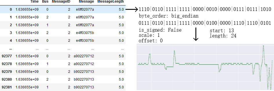
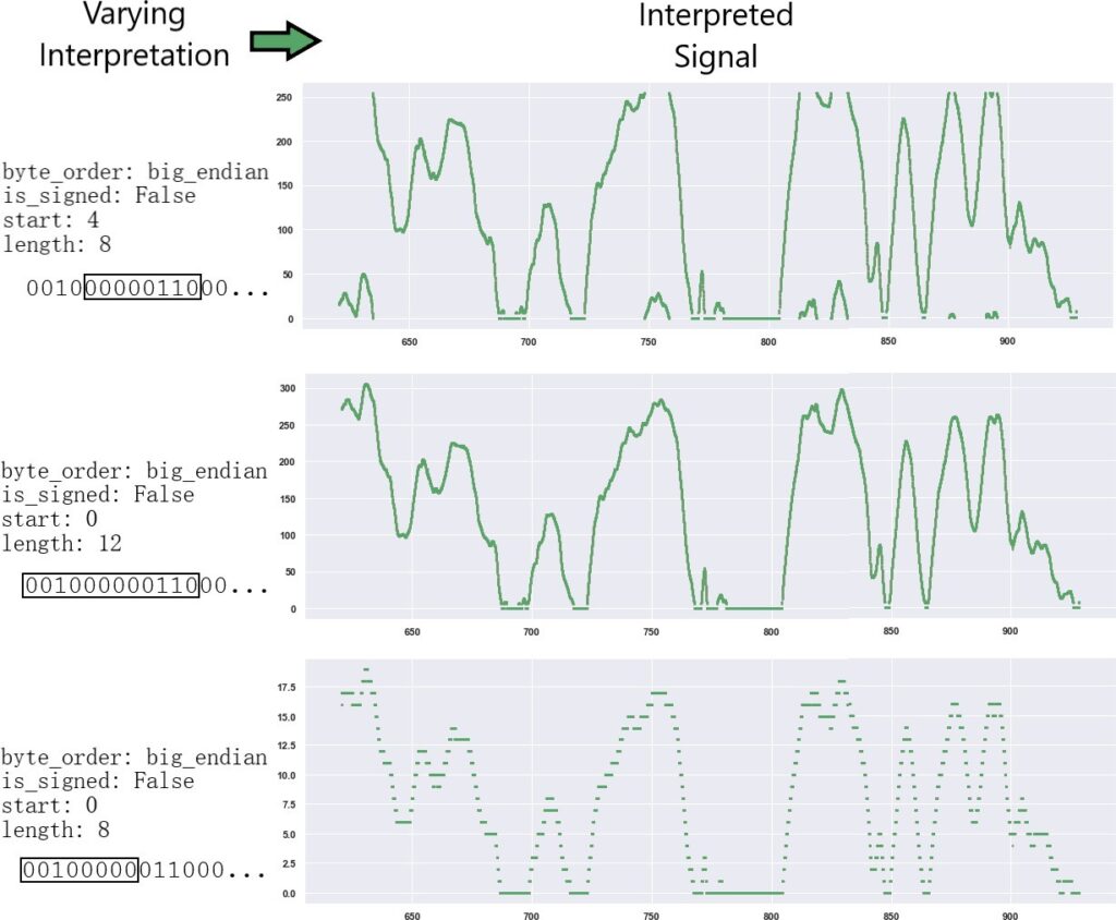
Algorithm 2, interpretive convolutions, were then used to generate a signal of the correct input size for the CAN classification network. This algorithm is similar to what Convolutional Neural Networks [17] do for images, but instead are interpretive convolutions for CAN messages. Differing sizes of bit widths are used to interpret the same message across all possible positions in the message. This generates a vector of varying bit boundaries, byte orders, and sign values used to interpret the message. Interpreting CAN signals with bit widths similar to the true bit width of a signal will generate time series signals which have similar behavior to the true signal, allowing the LSTM to learn from signal behaviors relevant to each type of signal. This behavior similarity is visually demonstrated in Figure 2.
Algorithm 2 Interpretive Convolutions
Require: msg is 64 bits
out ← []
for i from 1 to 61 do
out → interpret(msg, i:i+4, big, +) out → interpret(msg, i:i+4, little, -)
end for
for i from 1 to 57 do
out → interpret(msg, i:i+8, big, +) out → interpret(msg, i:i+8, little, +) out → interpret(msg, i:i+8, big, -) out → interpret(msg, i:i+8, little, -)
end for
for i from 1 to 53 do
out → interpret(msg, i:i+12, big, +) out → interpret(msg, i:i+12, little, +)
end for
for i from 1 to 49 do
out → interpret(msg, i:i+16, big, +) out → interpret(msg, i:i+16, little, +) out → interpret(msg, i:i+16, big, -) out → interpret(msg, i:i+16, little, -)
end for
scaled and shifted according to the training set means and ranges of the vectors, placing the vector values to be between the values of -1 and 1. This enables the network to identify signature patterns for each type of signal regardless of the signal’s order of magnitude, which is directly related to the length of the interpretation.
The final preprocessing step samples the convolutionally interpreted signals every 100 time-steps for a total of 100 samples. This sampling value was fixed because the data rates of broadcasted CAN messages reflect the relative rate at which the CAN signals on the message change in time. Various other sampling strides and sample counts perform similarly.
The layers of the CAN classification neural network model were as follows:
Fully Connected, 500 units LSTM, 256 units
LSTM, 256 units, dropout 0.1
Fully Connected, 100 units, dropout 0.1 Fully Connected, 50 units
Fully Connected, 12 units, sigmoid activation
The model’s objective was to correctly predict the presence of 11 signals from 100 sampled values from a convolutionally interpreted CAN message. All data were preprocessed according to the described algorithms. A prediction is only correct if the model predicts the presence of the relevant signal and the absence of all other signals.
An 80:20 train-test split was used to train and evaluate the model. The model was trained for 6 epochs on CAN message data collected from 3 hours of driving. The model achieved 0.8118 training set accuracy after 6 epochs of training, which took 3 hours on a 4.3 GHz processor (with multi-threading disabled). The model achieved 0.8170 test set accuracy.
4.2. Using CAN Classifier for Decoding
The CAN classifier network can be used to both detect specific signal types, as well as decode the exact bit boundaries of detected signals. CAN messages are first preprocessed according to Algorithm 2. The model can then predict the signal types transmitted on each message. Only signals which are predicted to be present with a probability of 80% or greater are accepted.
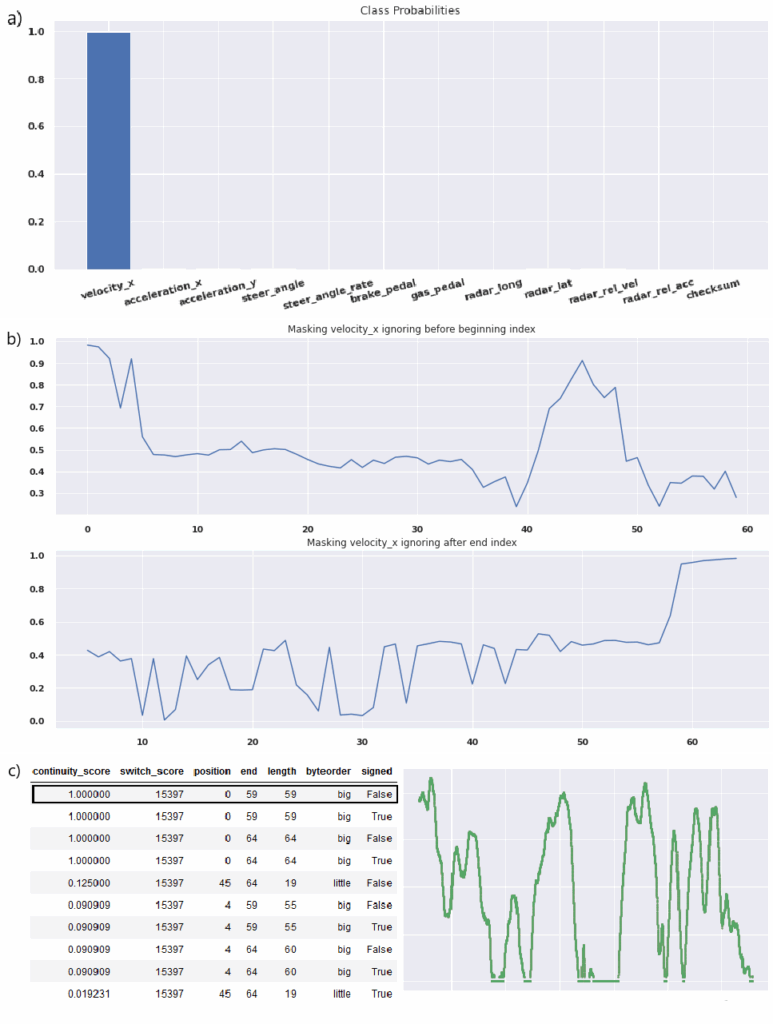
The bit boundaries of the signal can then be found using Algorithm ??, which iteratively masks the signal to evaluate which part of the message contributes to the prediction of the class of interest. This algorithm generates scores for each possible starting and ending bits of a signal. The left bit boundary is encoded as a peak in the starting scores, and the right bit boundary is encoded as a peak in the ending scores. Each boundary combination, endianness, and signedness are interpreted for each signal. Finally, these interpretations are filtered based on three criteria. First, the interpretations scored based on continuity. Continuity is approximated by counting the number of differences in value between two timesteps which are within 10% of the range of a signal, as shown in Equation 1. Only signals which have a continuity score of greater than 50% are accepted. Signals are then scored based on the rate at which they vary, which is the number of times the value changes — the highest score is accepted as the encoding. Finally, counter signals are filtered out [13]. The ultimate output from this filtering process is an endianness, signedness, and signal type label for each detected signal.
$$\text{score} = \frac{1}{\text{count}(\text{diff}(\text{signal}) > 0.1 * \text{range}(\text{signal})) + 1}\tag{1}$$
A raw signal value can be obtained by interpreting the original CAN message with the signal boundaries, endian- ness, and signedness from this decoding process. Figure 3 shows an example of this decoding workflow.
5. Results
CANClassify was evaluated on a previously undecoded vehicle, a 2020 Nissan Rogue Sport. The data was collected by interfacing with the ADAS module located in the passenger rear quarter panel. All messages on a single CAN bus were recorded over a 5 minute period. This shows the power of the model to identify useful signals even with small amounts of data. CANClassify identified, decoded, and labeled seven signals, of which two were radar-long signals, one was a radar-lat signal, one was a pb signal, one was an ax signal, and two were vx signals. In the final filtering stage, two of these seven signals were filtered out as counter signals.
The non-radar signals found were manually verified using Strym [18] and mapped to valid signal labels. The wheel speed signal was independently decoded on the vehicle using bit flipping techniques as described in previous literature.
The model predicted the same encoding for the wheel speed signal as was found manually. Figure 3 illustrates the decoding process as applied to the wheel speed signal.
The model was also successful at learning the signal behavior of more complicated signals, such as acceleration- and pedal-related signals. Figure ?? shows a signal that the model classified as a brake pedal signal. This signal is more likely to be associated with acceleration, but the model and decoding process obtained a sufficiently close labeling result, as braking is closely related to acceleration. This example demonstrates that CANClassify is able to learn signal features such as braking without having to individually define physical signal relationships (e.g., calculating an acceleration signal by differentiating wheel speeds and searching for signals that correlate with the differentiated value).
A single-core 4.3 GHz processor was used for evaluating the runtime of CANClassify. The time taken to decode using CANClassify is linearly correlated to the number
of messages and the length of the CAN data because the same convolutions are evaluated regardless of the message. Therefore, CANClassify will take the same time to decode any vehicle make and model, assuming the previous factors are constant. We evaluated on data from a five-minute drive, recording 129 CAN messages, where each message published at a rate of 400 bytes per second on average. CANClassify took 55 seconds to preprocess and classify all messages without decoding. The bit decoding process took 165 seconds per message on the same hardware. No- tably, the CANClassify method for decoding can be entirely parallelized across messages, across time, and across bit masks during bit decoding. With the same hardware and 16-threads, CANClassify only takes 3 seconds to classify all messages, and 10 seconds per message (on which a signal of interest is detected) to identify the correct encoding. There- fore, we conclude that CANClassify is competitive with the current state of the art while achieving the additional task of labeling discovered signals.
6. Discussion
In this work, we presented an alternative approach to CAN signal decoding. Many current CAN decoding methods, such as LibreCAN [13] and CAN-D [14], use signal- independent features such as bit flipping rates to identify and decode signals, and then rely on manual work and correlation with labeled ground truth signals to label the decoded signals. While there has been previous work that leverages known decodings to further decode CAN signals [15], there has been no corresponding work to automate the labeling of these signals. Our solution, CANClassify, leverages known encodings and labels to further accelerate both decoding as well as labeling.
However, more efficient CAN decoding brings up some concerns about the security and safety of these methods. As vehicles become more interconnected, it becomes increasingly likely that infrastructure is created for inter-vehicle communication. Adversarial attacks on physical CAN systems in conjunction with these new inter-vehicle communication protocols [19] could allow adversaries to remotely decode additional vehicles, or interfere with intra-vehicle CAN messages. Accelerated CAN decoding could also al- low attackers to more easily identify the CRC bits packaged with CAN signals, which act as a checksum and a way to detect modified or invalid CAN signals. Such an attacker could maliciously inject or modify CAN signals by correctly setting CRC signals to valid values.
Some intrusion detection methods have been developed to detect such attacks [20, 21]. Another simple solution to secure CAN data is the use of encryption. Encryption solutions have been demonstrated to be both feasible and fast enough to be used on modern CAN buses [22]. While signals could still be detected through power analysis, the true encoding, as well as the underlying value of the CAN signals, would be obfuscated — such a solution could only be defeated through a cryptographic attack.
7. Conclusion
We presented a novel method for decoding CAN signals from vehicle driving data by leveraging existing knowledge of CAN message encodings and signal dynamics. Instead of identifying features about the signal encodings them- selves, we use our network to identify features about signal behaviors. By using convolutional interpretations of CAN messages, our model can learn from known encodings and be used to identify the encodings of unknown signals. It is able to do so even with a small amount of driving data — a trained network is able to quickly decode signals as well as label them, a task that would normally require manual work for each type of signal.
Our solution was validated by evaluating the model on signals recorded from a previously undecoded vehicle. Encodings were validated by independently decoding the same signals using present techniques and using correlations to ground truth values.
Future directions for work include training on additional signal types. With our current method, COUNTER and CRC signals are sometimes detected as other PHYS signals (though they are ultimately filtered out of the output). By including these types of signals in the training set for the model, these over-detections can be mitigated. Additionally, we assume a consistent encoding for each signal. However, some signals are multiplexed in time over the same set of bits, where a single bit or a small number of bits are used to specify which signal is transmitted over the rest of the bits. By assessing the evolution of prediction probabilities across time, CANClassify has the potential to detect multiplexed signals and individually classify each multiplexed signal. However, additional work must be done to identify the multiplexing selection bit or bits.
Conflict of Interest The authors declare no conflict of interest.
Acknowledgment This material is based upon work sup- ported by the U.S. Department of Energy’s Office of Energy Efficiency and Renewable Energy (EERE) award number CID DE-EE0008872. The views expressed herein do not necessarily represent the views of the U.S. Department of Energy or the United States.
- M. Nice, S. Elmadani, R. Bhadani, M. Bunting, J. Sprinkle, D. Work, CAN Coach: Vehicular Control through Human Cyber-Physical Systems, p. 132–142, Association for Computing Machinery, New York, NY, USA, 2021.
- E. Baschab, S. Ball, A. Vazzana, J. Sprinkle, Safer Adaptive Cruise Control for Traffic Wave Dampening, p. 231–232, Association for Computing Machinery, New York, NY, USA, 2021.
- S. Jafarnejad, “Machine learning-based methods for driver identifica- tion and behavior assessment: Applications for can and floating car data”, 2020.
- M. Bertoncello, “Monetizing car data”, 2017.
- “Sae j1939 standards collection”, 1994.
- Comma.ai, “opendbc: The project to democratize access to the de-
- J. de Hoog, T. Bogaerts, W. Casteels, S. Mercelis, P. Hellinckx, “Online reverse engineering of can data”, Internet of Things, vol. 11, p. 100232, 2020, doi:https://doi.org/10.1016/j.iot.2020.100232.
- M. E. Verma, R. A. Bridges, J. J. Sosnowski, S. C. Hollifield, M. D. Iannacone, “CAN-D: A Modular Four-Step Pipeline for Compre- hensively Decoding Controller Area Network Data”, arXiv e-prints, arXiv:2006.05993, 2020.
- S. Siami-Namini, N. Tavakoli, A. Siami Namin, “A comparison of arima and lstm in forecasting time series”, “2018 17th IEEE Interna- tional Conference on Machine Learning and Applications (ICMLA)”, pp. 1394–1401, 2018, doi:10.1109/ICMLA.2018.00227.
- F. Karim, S. Majumdar, H. Darabi, S. Chen, “Lstm fully convolu- tional networks for time series classification”, IEEE Access, vol. 6, pp. 1662–1669, 2018, doi:10.1109/ACCESS.2017.2779939.
- R. Pascanu, C. Gulcehre, K. Cho, Y. Bengio, “How to construct deep recurrent neural networks”, 2014.
- M. Marchetti, D. Stabili, “Read: Reverse engineering of automotive data frames”, IEEE Transactions on Information Forensics and Security, vol. 14, no. 4, pp. 1083–1097, 2019, doi:10.1109/TIFS.2018.2870826.
- M. D. Pesé, T. Stacer, C. A. Campos, E. Newberry, D. Chen, K. G. Shin, “Librecan: Automated can message translator”, “Proceedings of the 2019 ACM SIGSAC Conference on Computer and Communications Security”, CCS ’19, p. 2283–2300, Association for Computing Machinery, New York, NY, USA, 2019, doi:10.1145/3319535.3363190.
- M. E. Verma, R. A. Bridges, J. J. Sosnowski, S. C. Hollifield,
M. D. Iannacone, “Can-d: A modular four-step pipeline for comprehensively decoding controller area network data”, 2020, doi: 10.48550/ARXIV.2006.05993. - A. Buscemi, I. Turcanu, G. Castignani, R. Crunelle, T. Engel, “Can- match: A fully automated tool for can bus reverse engineering based on frame matching”, IEEE Transactions on Vehicular Technology, vol. 70, no. 12, pp. 12358–12373, 2021, doi:10.1109/TVT.2021.3124550.
- M. Bunting, R. Bhadani, J. Sprinkle, “Libpanda: A high performance library for vehicle data collection”, “Proceedings of the Workshop on Data-Driven and Intelligent Cyber-Physical Systems”, DI-CPS’21, p. 32–40, Association for Computing Machinery, New York, NY, USA, 2021, doi:10.1145/3459609.3460529.
- K. Fukushima, “Neocognitron: A self-organizing neural network model for a mechanism of pattern recognition unaffected by shift in position”, Biological Cybernetics, vol. 36, no. 4, pp. 193–202, 1980, doi:10.1007/BF00344251.
- R. Bhadani, M. Bunting, M. Nice, N. M. Tran, S. Elmadani, D. Work, J. Sprinkle, “Strym: A python package for real-time can data log- ging, analysis and visualization to work with usb-can interface”, “Proceedings of the 2nd Workshop on Data-Driven and Intelligent Cyber-Physical Systems”, 2022.
- J. Kleylein-Feuerstein, F. Joas, R. Steinhilper, “Remanufacturing of electronic control units: An rfid based (service) interface”, Procedia CIRP, vol. 29, pp. 168–172, 2015, doi:https://doi.org/10.1016/j.procir. 2015.02.163, the 22nd CIRP Conference on Life Cycle Engineering.
- M. Markovitz, A. Wool, “Field classification, modeling and anomaly ion in unknown can bus networks”, Veh. Commun., vol. 9, pp.–52, 2017.
- M. H. Shahriar, Y. Xiao, P. Moriano, W. Lou, Y. T. Hou, “Canshield: Signal-based intrusion detection for controller area networks”, 2022.
- O. Avatefipour, H. Malik, “State-of-the-art survey on in-vehicle net- ation (can-bus) security and vulnerabilities”, 2018,
0.48550/ARXIV.1802.01725.