Trajectory Correction Method of Motion Description Language of Vertebral Milling Robot based on Force Feedback

(This article belongs to the Special Issue on Special Issue on Multidisciplinary Sciences and Advanced Technology (SI-MSAT 2022) and the Section Automation and Control Systems (ACS))
Export Citations
Cite
Ding, W. , Liu, Z. , Wang, H. and Cui, L. (2022). Trajectory Correction Method of Motion Description Language of Vertebral Milling Robot based on Force Feedback. Journal of Engineering Research and Sciences, 1(10), 26–35. https://doi.org/10.55708/js0110005
Wei Ding, Zhaoming Liu, Hongwei Wang and Long Cui. "Trajectory Correction Method of Motion Description Language of Vertebral Milling Robot based on Force Feedback." Journal of Engineering Research and Sciences 1, no. 10 (October 2022): 26–35. https://doi.org/10.55708/js0110005
W. Ding, Z. Liu, H. Wang and L. Cui, "Trajectory Correction Method of Motion Description Language of Vertebral Milling Robot based on Force Feedback," Journal of Engineering Research and Sciences, vol. 1, no. 10, pp. 26–35, Oct. 2022, doi: 10.55708/js0110005.
In the real-time control procession of the vertebral milling robot, there are problems such as heavy workload of the operator, long working time, operational tremble and complicated procession. In order to solve the clinical practical basic problems such as avoiding excessive milling and force perception control of vertebral milling robot, this paper proposes a method of trajectory correction of motion description language of milling robot based on force feedback. The task of trajectory correction of the milling robot oriented to force feedback, on the basis of ensuring the atom relationship of motion description language, defines seven motion atoms for the function of avoiding excessive milling during the actual operation of the milling robot. A milling robot experimental system is built with a force feedback control handle and a milling robot. Experiments are carried out on the trajectory correction method of the milling robot based on the motion description language. The experimental results verify the feasibility and effectiveness of this method. The innovation of this paper is reflected in the following two aspects. The use of force feedback to define and model motion description language atoms is an innovation, and the application of motion description language trajectory correction method to the field of vertebral milling robots is an application innovation.
1. Introduction
1.1. Vertebral milling robot
This template, In recent years, with the rapid development of society, the problem of aging population structure has become more and more serious. Spinal stenosis represented by lumbar disc herniation is a relatively common back pain caused by long-term compression of the medial spinal nerve by the spinal canal. The incidence of diseases, especially elderly people, is particularly high [1].
As people get older, the physiological functions of the human spine gradually degenerate, such as spinal hyperplasia and lamina thickening, which can cause the spinal canal space to become smaller and compress the spinal nerves. The degenerative condition can cause numbness and pain in the lower limbs of the patient, and in severe cases, it can lead to paralysis [2]. The most effective surgical treatment for this disease is lamina decompression, and vertebral milling is an important step in the process of lamina decompression [3].
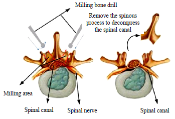
Vertebral lamina milling requires the doctor to mill the lamina of the lesion area and remove the spinous process with the aid of positioning and navigation, and mill the V-shaped groove on one or both sides of the spinous process of the spine, as shown in Figure 1. Expand the space and scope of the spinal nerves in the spinal canal, so that the compression of the vertebral lamina wall on the nerves and blood vessels can be released, and the “single window” or “double window” operation of the vertebral lamina can be realized [4], so that the spinal nerves and vertebrae joints return to normal functions.
As we all know, the blood vessels and nerves that connect the brain and various organs are scattered around the spinal canal, and the risk of spinal surgery is higher. Improper operation during the surgery may damage the nerves and blood vessels around the spinal canal. The small residual amount of milling the lamina may damage the nerves in the spinal canal, and the excessive residual amount may not achieve the effect of decompression of the spinal nerves [5]. During the milling operation, the doctor basically relies on the operating experience to control the strength and feed depth of the milling. Therefore, doctors lacking experience in hand manipulation and strength cannot guarantee the success rate of surgery, and may cause surgical injury to patients. Medical surgery hospitals urgently need more advanced assistive robotic equipment to improve the current surgical situation [6].
In the field of orthopedic robots, the United States and Europe are at the leading level, and various countries in Asia and Europe are actively investing and developing. Common doctor operations in spinal surgery include drilling and milling. As early as 1992, French Sautot et al. used CT images to drill nail and used PUMA spinal surgery assistant robots to assist doctors in drilling nail path. In 2003, the second-generation Renaissance spine assist robot system developed by Israel’s Mazor company realized automatic posture adjustment to assist doctors in drilling nail path [7]. In 2006, the VectorBot spine surgery robot system developed by Ortmaier at the German Aerospace Center can realize the drilling and milling operations.
In China, the research on orthopedic surgical robots is still in the initial stage of accumulation, lagging behind Europe and the United States. In 2006, Wang of Beijing University of Aeronautics and Astronautics developed a spinal surgery milling system, which determined the state of vertebral milling by monitoring the force change of the bone drill when milling the vertebrae. In 2019, Li of Harbin Institute of Technology independently developed clinical-oriented SRAS image navigation, data acquisition and other software systems, and achieved many results in robotic laminar surgery planning methods.
1.2. Control method of surgical milling robot
Human spine bone is divided into two types, cortical bone and cancellous bone. The milling operation of spinal decompression and the drilling operation of screw insertion are both the inner cortical bone as a safe surgical restraint to avoid damage to the nerves and spinal cord in the spinal canal of the patient [8-9].
In recent years, scholars from various countries had also proposed a variety of effective control methods for the surgical operation of vertebral milling robots. Deng of the University of Hamburg used fuzzy control to adjust the feed depth and speed of the milling head in the process of vertebral milling, which improved the quality and efficiency of milling [10]. Wang used a parametric modeling method to identify the bone layer, but this method was based on the milling force data, and the difference in environmental parameters may cause the identification results to be inaccurate [11].
Compared with doctor operation, medical milling robot has many advantages such as anti-fatigue, anti-radiation and good stability [12]. In summary, the research on the control of medical milling robots is still in the accumulation stage. It is necessary to further improve the milling robot modeling and milling control methods.
2. Force Feedback and Motion Description Language
2.1. Force feedback
At this stage, with the practical application of milling robots, force feedback technology has become a very important information interaction technology for milling robots [13-15]. The introduction of force feedback into the milling robot system will increase the amount of information feedback and the milling accuracy of the doctor, which in turn will improve the milling quality, reducing misoperation, and shortening the milling operation time [16]. There are two types of force feedback methods for milling robots, direct feedback and perception substitution [17]. The direct feedback method is that the force sense information is directly fed back to the operator through the tactile device [18-19]. In short, we use the operation control unit with force feedback function to perform force perception, which can increase the immersion and realism of the doctor during the operation.
2.2. Motion Description Language
The basic physical model of the Motion Description Language (MDL), is also known as the motion state machine model. The motion state machine model is to form a mapping relationship from the state space to the output space. The motion state machine model definition [20-21] is:
$$\dot{x} = G(x)\left(u + k(y)\right), \quad y = h(x) \tag{1}$$
Among them, x, y and u are the vector functions of the time variable t, G is the matrix, and h and k are the mapping of the vector space.
Under the framework of motion description language control theory, the control process and state process of a complete control system can be decomposed into several small segments and sub-processes. Each sub-process is expressed by a triple (u, k, t), this triple is called a motion atom, where u is the control input, k is the control law, and t represents time. Represent a continuous state system in segments, and then use parameterized motion atoms (u, k, t) to represent each sub-process, and reconstruct the original continuous system in the form of a sequence of motion atoms, we can use a set of discrete motion atom symbol sequences to drive the original continuous system.
The triples (ui, ki, Ti) are called “motion atom”, and the set consisting of these triples is called the “motion alphabet”. The robot control process program is a symbol string composed of motion atoms to realize the drive and control of the robot. Representing a continuous system in segments, and then expressing each segment with parameterized motion atoms, a sequence of discrete symbols can be used to drive the continuous system.
It is described by the spatial kinematics of the robot of end tool coordinate system. If the end of robot moves along a curve in space, the general form of the curve equation [22] is:
$$\left\{ \begin{aligned} F_1(x,y,z) &= 0 \\ F_2(x,y,z) &= 0 \end{aligned} \right. \tag{2}$$
This curve is simplified as F(X)=0, where Χ=(x,y,z)T,
$$\mathbb{F}(\mathbf{X}) = \begin{pmatrix} F_1(x, y, z) \\ F_2(x, y, z) \end{pmatrix} \tag{3}$$
If the initial state of the robot is x0=x(t0), after receiving the combination of motion atoms (u1, k1, T1) (u2, k2, T2)…(un, kn, Tn), the system state motion law can be expressed as:
$$\begin{cases}
\dot{x} = G(x)\left(u_1 + k_1(y)\right); & t_0 \leq t < t_0 + T_1 \\
\dot{x} = G(x)\left(u_2 + k_2(y)\right); & t_0 + T_1 \leq t < t_0 + T_1 + T_2 \\
\vdots & \vdots \\
\dot{x} = G(x)\left(u_n + k_n(y)\right); & t_0 + \sum\limits_{i=1}^{n-1} T_i \leq t < t_0 + \sum\limits_{i=1}^{n} T_i
\end{cases} \tag{4}$$
In the above formula, u, X, and y are functions of t. u is the system input function. X is the n-dimensional system state function. y is the output function of the system, and k is the n-dimensional state feedback.
From the perspective of bionics and artificial intelligence, robot behavior is defined as a collection of continuous actions of a robot with certain characteristics. The design of the motion description language atom function is used to express a certain behavioral feature of the robot, and the robot’s behavior is corresponding to the motion atoms of the motion description language. Designing a set of symbol strings composed of motion atoms is called motion planning of a robot. The structure of the robot control system based on the motion description language method is shown in Figure 2. Overall, the robot controller is responsible for path planning and motion description language atom sequence generation.
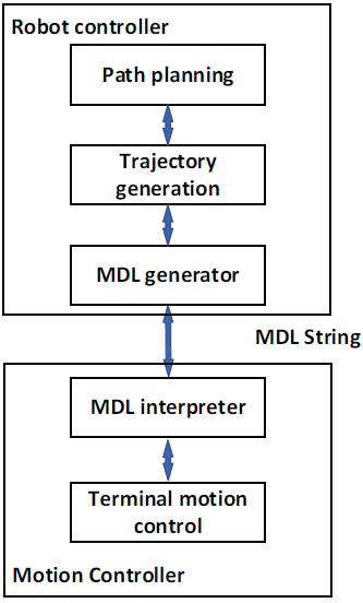
The compiler receives a sequence combination of motion atoms, and then the compiler translates this sequence into segments and maps the motion segment group. The slave robot can autonomously complete the motion segment expressed by the atom. The master operator organizes the motion control program sequence according to the robot’s motion alphabet, and the slave robot actuator generates the actual motion to complete the robot’s planning task.
2.3. Motion Description Language Model of the Vertebral Milling Robot based on Force Feedback
The medical milling robot is applied to the milling process of human vertebral laminae, and its expected movement path has been clarified. However, due to the large differences in the stiffness and hardness of human tissue, cortical bone and cancellous bone, the robot may encounter different resistance and impedance conditions during real-time operations. In the task of orthopedic milling operations, the robot is required to have a certain degree of compliance with the force of the human tissue to avoid excessive damage. Therefore, this article refers to forming an admittance model between the robot and the force feedback sensor, and modeling the working environment as a spring system model [23].
The impedance factor and force feedback are used as the control reference factors for adjusting the robot trajectory. In the MDL control process, not only the position and posture, but also the resistance factor must be considered. That is, the force feedback has an influence on the MDL control process, forming an admittance factor, and achieving force-based feedback MDL control. Due to the effects of various organizations and resistances, the robot’s planned path deviates from the actual path, and the robot’s posture needs to be adjusted to achieve the desired trajectory planning [24].
Admittance control is a control method based on the dynamic relationship between force and speed or position. The admittance model can be regarded as the inverse process of the impedance model [25].
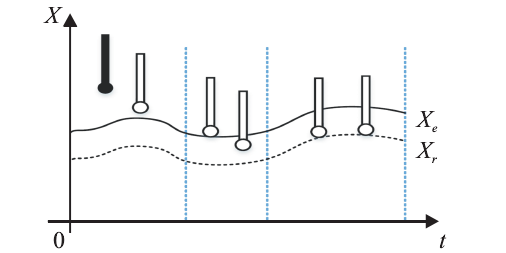
The contact process between the milling robot and the environment can be divided into two stages, (1) non-contact and no-load spatial movement; (2) constrained spatial movement after contact with the environment [26]. The contact procession is shown in Figure 3. Xe represents the position of the working environment, Xr represents the actual position of the end effector of the milling robot [27-28].
In this paper, the control algorithm adopts the admittance control method to realize the control process of the contact force. The control block diagram is shown in Figure 4. The model of force-sensing milling robot system is simplified to a “spring-damping” second-order system model, and the working environment model is simplified to a first-order spring model [29-30].
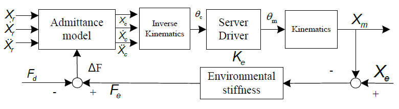
In Figure 4, the meaning of each variable is shown in Table 1. In general, position control satisfies the variable Xc=Xm, and the error between the expected reference trajectory and the actual trajectory of the robot is E=Xm−Xr= Xc−Xr.
Table 1: Variable Table of Admittance Control Model
NO. | Variable name | Variable meaning |
1 | Xm | The actual track position of the milling robot |
2 | Xc | Trajectory position command sent to the milling robot |
3 | Xr | The trajectory position variable corresponding to the desired tracking force at the end of the milling robot |
4 | Ke | Environmental stiffness |
5 | Xe | Environment location variables |
6 | Fd | Desired tracking power |
7 | Fe | The actual contact force obtained by the sensor |
8 | ∆F | Force error of robot |
9 | E | Trajectory deviation |
Through the above-mentioned environmental model analysis, the working environment of the milling robot is assumed to be a first-order spring model [31-32]. Then the contact force between the milling robot and the environment is Fe= Ke(Xe−Xm) = Ke(Xe−Xc), and the deviation between the robot’s expected tracking force and the actual contact force obtained by the sensor is ∆F=Fe−Fd.
In the admittance control model shown in Figure 4, the expression of the admittance control model is the second-order function K(s) = 1/(Ms2+Bs+K), that is, the robot force error ∆F and trajectory error E are the second-order differential system of “spring-damping”, the expression is as follows,
$$M\frac{d^2 E(t)}{dt^2} + B\frac{dE(t)}{dt} + K E(t) = \Delta F(t), \tag{5}$$
In the above formula, K, M and B represent stiffness coefficient, mass coefficient and damping coefficient, respectively.
According to the force error ∆F, the track position Xc sent to the milling robot can be obtained by calculation, expressed as Xc=Xr+E=Xr+∆F·K(s).
At this time, E=Xc−Xe, analyzing the impedance characteristics of unidirectional force error and position error, e=xc-xe, Suppose the estimated value of environmental position = xe−δxe, after calculation, its corresponding trajectory position error ê=e+δxe, and obtain the equation
$$f_e – f_d = m\ddot{e} + b\dot{e} = m\left(\ddot{e} + \delta \ddot{x}_e\right) + b\left(\dot{e} + \delta \dot{x}_e\right), \tag{6}$$
Among them, fe and fd are time-varying functions, and the force tracking error is a time-varying function.
The problem of trajectory correction based on force feedback is the most basic practical problem in the clinical application of vertebral milling robots. Converting it into an experimental task can be summarized as follows, the vertebral milling robot moves on a planned trajectory, performs milling operations on the outer layer of cancellous bone. If reaches the inner layer of cortical bone according to the force feedback handle feedback exceeding the admittance parameter threshold, then switch the MDL atoms to modify the trajectory according to the current movement situation to achieve the effect of protecting the nerves in the vertebrae.
Based on the analysis of the above operation tasks, this article defined seven control atoms, which described the movement of the vertebral milling robot along the space linear motion correction, the plane circular motion correction, and the space circular motion correction under the description of the tool coordinate system atoms, their motion atoms and motion alphabet definitions are shown in Table 2.
Table 2: Description Table of Milling Robot Motion Atoms
No. | Behavior classification | MDL atoms | Switching conditions |
1 | Linear motion regression correction | (u1,k1,δ1) | The feedback force is greater than the threshold value F1 |
2 | Plane left circular motion correction | (u2,k2,δ2) | Right plane circular motion, the feedback force is greater than the threshold F2 |
3 | Plane right circular motion correction | (u3,k3,δ3) | Left plane circular motion, the feedback force is greater than the threshold F3 |
4 | Correction of the forward movement of the left circle of the three-dimensional cylinder | (u4,k4,δ4) | The rightward three-dimensional cylindrical arc backward movement, the feedback force is greater than the threshold F4 |
5 | Correction of the forward movement of the right circle of the three-dimensional cylinder | (u5,k5,δ5) | The backward movement of the three-dimensional cylinder arc to the left, the feedback force is greater than the threshold F5 |
6 | Three-dimensional cylindrical left arc backward motion correction | (u6,k6,δ6) | Three-dimensional cylindrical arc forward motion to the right, the feedback force is greater than the threshold F6 |
7 | Three-dimensional cylindrical right arc backward motion correction | (u7,k7,δ7) | Leftward three-dimensional cylindrical arc forward motion, the feedback force is greater than the threshold F7 |
The motion atom σ1=(u1, k1, δ1) is “the vertebral milling robot moves back and forth along a straight line in the tool coordinate system”. When the operator performs milling tasks through the robot system, the interaction force between the end effector of the milling robot and the lamina tissues that he cares about is greater than the threshold, which means, the milling force is too large, and corresponding corrections and adjustments is needed. Therefore, the linear motion of the robot in the tool coordinate system is defined as the control atom.
If the direction vector of the end effector along a straight line in the tool coordinate system is s=(m,w,p)T and m≠0, then the linear motion equation [33-34] can be expressed as
$$\left\{ \begin{aligned} F_1(x, y, z) &= wx – my \\ F_2(x, y, z) &= px – mz \end{aligned} \right. \tag{7}$$
The system state equation based on MDL can be expressed as formula (4),
$$\mathbf{u}_1 := \boldsymbol{\xi}_{\perp,1} \cdot \left( {}^{\top} J(\theta) \right)^{-1} \cdot (m \;\; w \;\; p \;\; 0 \;\; 0 \;\; 0)^{\top} \tag{8}$$
$$\mathbf{k}_1 := -\boldsymbol{\xi}_{\parallel,1} \cdot \left( {}^{\top} J(\theta) \right)^{-1} \cdot \left( \begin{array}{cccccc} w & -m & 0 & 0 & 0 & 0 \\ p & 0 & -m & 0 & 0 & 0 \end{array} \right)^{\top} \begin{pmatrix} wx – my \\ px – mz \end{pmatrix} \tag{9}$$
$$y = (x_c, \dot{x}_c, \ddot{x}_c)^{T} \tag{10}$$
∆f=fe-fd, u=(∆f) is the control input, y is the control system output. k1(u, y) is the control law of u1 atom, and its expression is as follows,
$$k_1(\mathbf{u}, \mathbf{y}) := \left\{ \begin{aligned}
\ddot{x}_c(f) &= \ddot{x}_e(f) + \frac{1}{m} \left[ \Delta f(f) – b(f)(\dot{x}_c(f – F) – \dot{x}_e(f)) \right] \\
\dot{x}_c(f) &= \dot{x}_c(f – F) + \ddot{x}_c(f) \times F \\
x_c(f) &= x_c(f – F) + \dot{x}_c(f) \times F
\end{aligned} \right. \tag{11}$$
δ1 is the execution condition function of the atom (u1, k1, δ1). It is a function defined in the output space of the system. The value range is {0,1}. When δ1(y)=0, it means (u1, k1, δ1) continues to act on the control system, and when δ1(y)=1, it means that the slave robot system will execute the next motion control atom [35]. δ1 is defined as,
$$\delta_1(\mathbf{y}) = \begin{cases}
0, & \text{if } \rho_1(\mathbf{y}) – \rho_1 < 0 \\
1, & \text{if } \rho_1(\mathbf{y}) – \rho_1 \geq 0
\end{cases} \tag{12}$$
Among them, ρ1(y) is the feedback force of the end mechanism motion when the atom σ1 is executed, and ρ1 is the given feedback force threshold F1. In the same way, define (u2,k2,δ2),…(u7,k7,δ7), and the basic parameter variables can be deduced by analogy. When the milling robot approaches the desired trajectory in the advancing direction, the robot azimuth angle θ will tend to the desired straight line. When the force feedback is greater than the threshold value F1, the backlash correction is performed immediately, and the K1 control law is switched, and finally back to the planned trajectory to avoid damage to the vertebra due to excessive milling. δ1 is a function defined on the output space of the robot. (u2,k2,δ2), (u3,k3,δ3),…(u7,k7,δ7) for symbol definition and function description refer to (u1,k1,δ1).
3. MDL Trajectory Correction Experiment of Vertebral Milling Robot based on Force Feedback
3.1. Experimental Platform of Vertebral Milling Robot
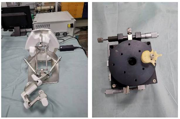
The milling robot system is mainly composed of two parts, a three-dimensional force feedback handle and a milling robot platform. The platform uses a three-dimensional force feedback handle to control the milling robot. The control handle adopts the force feedback sensing device independently developed by this group, as shown in Figure 5.
The control handle of the robot adopts an enhanced three-dimensional structural design, which integrates the spatial perception display method of three-dimensional force perception and three-dimensional force feedback. The platform implements the terminal handle enhancement control function for the force feedback handle, which can realize the high-precision control of the handle and the expression function of multi-dimensional force feedback information.
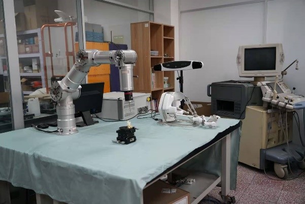
The experimental platform of the milling robot is shown in Figure 6. Its control handle has the function of direction control of up, down, left and right. It also includes the function of controlling forward and backward of the controlled object. It sends console commands to the milling robot. The interactive information of the milling environment can be fed back to the operating handle, so as to make corresponding adjustments according to actual needs.
Robot behavior planning refers to the rational definition of robot action atom set and optimization of the atom set to achieve the balance between the completion of the work task and the underlying motion control for robot.
3.2. Experiment and Analysis of Trajectory Correction of Vertebral Milling Robot Motion Description Language based on Force Feedback
Through the above analysis of the functional requirements of the milling robot, the motion of the milling robot is mainly divided into three categories: linear motion, plane motion and spatial arc motion, which also conform to the characteristics of the three-dimensional motion atoms of the milling robot. The control method of the milling robot adopts the basic behavior set up, down, left and right, and its characteristic behavior set is, straight line k1 retreat correction, plane left arc k2 correction, plane right arc k3 correction, three-dimensional space arc k4 forward motion correction and three-dimensional space circular arc k5 retreat motion correction. Seven action atoms are formed, (u1, k1, δ1), (u2, k2, δ2), (u3, k3, δ3), … , and their movement description language atom table is shown in Table 2.
The meaning of atom (u1, k1, δ1) is shown in section 2.3. Among them, v0 is a constant parameter, u and k are functions of the direction vector of the milling robot’s motion trajectory, and δ is the state digital quantity of whether the milling robot’s motion trajectory exceeds the threshold, and it is a function defined in the robot output space. The definition and function description of (u2, k2, δ2) … (u7, k7, δ7) refer to atom (u1, k1, δ1). According to the definition of the above atoms, the movement alphabet of the milling robot is obtained, Σ={(u1,k1,δ1), (u2,k2,δ2), (u3,k3,δ3), (u4,k4,δ4),( u5,k5, δ5),( u6,k6, δ6),( u7,k7, δ7)}.
Through the above behavior planning of the vertebral milling robot, it can realize the atom switching and trajectory correction when the force feedback is greater than the threshold, and realize the protection of the spinal canal, soft tissue and nerves. This is the great advantage of the motion description language control model.
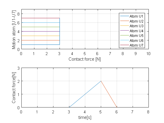
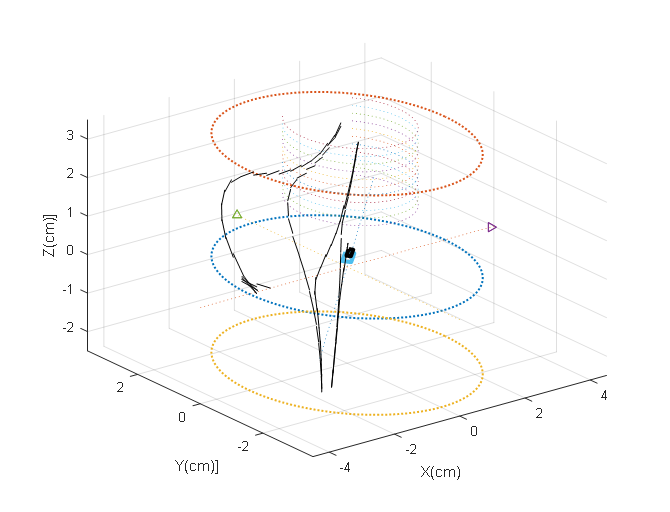
In the operating environment of the vertebral milling robot, the force threshold is set by the value of the force feedback. When the contact force is greater than the threshold, the motion description language atom is triggered to modify the trajectory, and the contact force between the end of robot and the tissue drops immediately. As shown in Figure 7(below). When the robot moves with the U1 atom, it interacts with the boundary vertebra. When the interaction force is greater than the force threshold, the robot switches to the Um atom for corrective movement. When the Un atom movement interacts deeply with the vertebra, continue switch other correction atom to form a robot MDL atom correction strategy based on the force feedback threshold, as shown in Figure 7(above). Therefore, the force-constrained switching trajectory correction function is a characteristic function of the MDL control method.
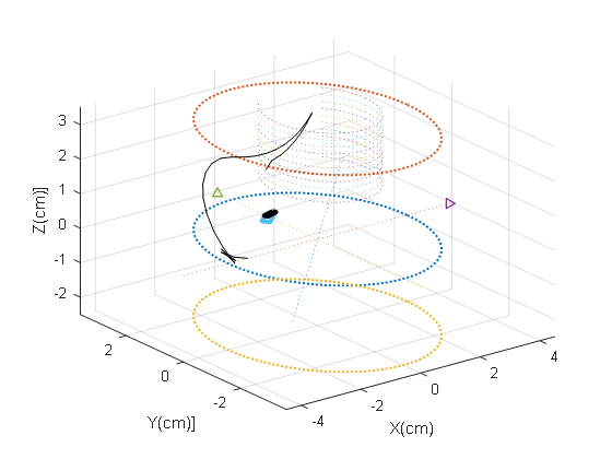
The force feedback threshold and the motion description language atoms are used for switching correction to realize the dynamic trajectory correction of the milling robot. The Matlab2016 simulation platform is used to simulate the trajectory correction based on MDL. Starting from the initial point, the milling robot moves in three-dimensional space with a planned path, as shown in Figure 8. When the robot moves to the vertebra for milling, while the feedback force is greater than the threshold, the MDL atom trajectory is corrected immediately, and the movement continues after switching to adjust the control law to the planned trajectory, as shown in Figure 8. Therefore, it can be seen that the motion atom switching correction based on MDL can realize the robot trajectory correction function based on force feedback in three-dimensional space and trajectory control based on constraints.
The working environment parameters are described as follows, in the milling and processing vertebra environment, the space environment of the milling robot is restricted to a cylindrical area with a radius of R=3cm. The cylindrical area above (-2, -2, 0) is the position of the vertebra. When the initial position of the robot end is (-2, 0, 0) and the posture is toward the Y-axis side, as shown in Figure 8, the task of trajectory correction is realized by switching the MDL atoms based on force feedback.
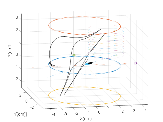
The experiment procession and analysis are as follows, the experiment uses seven atoms to describe the behavior of the milling robot, and conducts the milling robot control experiment. The MDL atom table is shown in Table 2. During the control procession, the control angle can be adjusted according to the position and posture of the milling robot. The three-dimensional motion curve of the milling robot is shown in Figure 9 and Figure 10. The experiment includes manual control mode and MDL correction mode to compare the advantages and disadvantages of the two control modes.
In the manual control mode, the running trajectory of the end of the milling robot is shown in Figure 9. It can be seen that in the manual control mode controlled by the handle controller, the running trajectory has fluctuations and discontinuities, and the trajectory is determined by operator through visual feedback and force feedback, so there are problems such as inaccurate control and hand tremble. In addition, the use of visual feedback to control the milling robot has the problem of information delay from the controller to the robot, which will also cause fluctuations and discontinuities in the end trajectory of the milling robot. Therefore, the manual control method still has obvious shortcomings.
The trajectory correction method based on the MDL is shown in Figure 10. The end of the milling robot moves upward to the edge of the vertebra in the forward direction of the planned trajectory. After the force feedback is greater than the threshold, the k5 correction atom is used to perform backward motion. Then move to the vertebral processing area in the forward direction of the planned trajectory. Finally, the end of robot uses k5 atom to correct the trajectory, completing the task of using force feedback to correct the trajectory.
The motion trajectory of the milling robot based on the MDL method is shown in Figure 10. The solid line starts from the initial point (-2, 0, 0). For the convenience of experimental visual observation, the movement procession of the end of the milling robot is mapped to the XOY two-dimensional plane in real time, so as to observe its real-time position and movement procession.
Compare the manual control mode and the MDL control mode, and analyze from the two aspects of accuracy and time of control. Since the MDL trajectory correction belongs to the automatic control of the underlying motion, the motion trajectory of the MDL correction is continuous and the control accuracy has a high level. In the manual control mode, humans make judgments through actual vision, and there are disadvantages such as trembles at the end of the robot and discontinuous motions with time delay. From the aspect of the workload of the operator, the manual mode requires the operator to control and judge the whole control procession, and the operator is easy to operate fatigue. While in the MDL method to correct the trajectory, automatic trajectory correction can be realized through force feedback to ensure the milling operation safety. Therefore, the trajectory correction method of the milling robot based on MDL has obvious advantages.
It can be seen from Figure 10 that the trajectory correction MDL method of the vertebral milling robot can well complete the trajectory correction task under the constraint condition. It is verified by experiments that the trajectory correction method of the milling robot based on MDL is accurate and effective.
4. Conclusion
Based on the characteristics of the operation of the vertebral plate milling robot, based on the data processing of the force feedback, a motion atom planning correction model based on the motion description language and force feedback is proposed. Atom planning ensures that the motion description language can meet the trajectory correction requirements of the milling robot. Compared with the real-time control of the traditional milling robot, it reduces the risk of excessive milling operation, improves the safety performance of the milling robot, and provides a more effective trajectory correction that conforms to the operating characteristics for the use of the milling robot. The method improves the safety and reliability of the vertebral milling robot. The limitations of the trajectory correction method of the laminar bone milling robot proposed in this paper are mainly reflected in the high accuracy requirements of the force sensor.
In the actual clinical application, the restriction condition of prohibiting switching within 1-2 seconds should be added to the switching conditions of the atoms, which has prevented the too frequent switching of the correction atoms. If the correction atom is frequently triggered within 1-2 seconds, the local space micro-vibration of the milling robot will be formed, and the long-term micro-vibration is not conducive to the stable control of the robot. Therefore, in order to ensure the stability and safety of the milling robot system, atom switching constraints should be added.
A milling robot control system was established with a milling robot and an experimental platform. Aiming at the task of vertebral milling based on force feedback, a reasonable behavior model of the milling robot is constructed. Through the space motion simulation experiment and comparison, the feasibility and effectiveness of the trajectory correction method based on the motion description language are verified. Future research will mainly focus on introducing the force feedback and visual feedback functions of the milling robot at the same time to assist the operation tasks of the milling robot.
Conflict of Interest
The authors declare no conflict of interest.
Acknowledgment
This paper was funded by the National Natural Science Foundation of China Cooperation Program (U2013208) and the Young and Middle-aged Science and Technology Innovation Talent Plan of Shenyang City (RC210314).
No related articles were found.