Smart Vehicle Safety System Using Arduino: An Experimental Study in Bahrain’s Driving Conditions
(This article belongs to the Section Automation and Control Systems (ACS))
Export Citations
Cite
Farag, Y. R. and Jasson, B. (2024). Smart Vehicle Safety System Using Arduino: An Experimental Study in Bahrain’s Driving Conditions. Journal of Engineering Research and Sciences, 3(11), 74–80. https://doi.org/10.55708/js0311006
Youmna Rabie Farag and Bintu Jasson. "Smart Vehicle Safety System Using Arduino: An Experimental Study in Bahrain’s Driving Conditions." Journal of Engineering Research and Sciences 3, no. 11 (November 2024): 74–80. https://doi.org/10.55708/js0311006
Y.R. Farag and B. Jasson, "Smart Vehicle Safety System Using Arduino: An Experimental Study in Bahrain’s Driving Conditions," Journal of Engineering Research and Sciences, vol. 3, no. 11, pp. 74–80, Nov. 2024, doi: 10.55708/js0311006.
The high rate of vehicle accidents is increasingly linked to drivers failing to maintain adequate safety distances between their vehicles and those in front. This issue is exacerbated by varying weather conditions such as rain, sandstorms, and fog. To mitigate this problem, we propose an Arduino-based intelligent system designed to assist drivers in maintaining safe distances and adjusting their speed accordingly. This system integrates an ultrasonic distance sensor, a rain sensor, a liquid crystal display with I2C, four gear motors, a motor driver, and an Arduino UNO. The ultrasonic sensor measures the distance to the vehicle ahead, and based on this data, the system calculates the recommended speed using an equation derived from safe distance calculations for different speeds. In adverse weather conditions, detected by the rain sensor, the system adjusts the equation to account for reduced visibility and road traction. This ensures that the recommended speed remains safe under varying environmental conditions. Experimental results from multiple locations across Bahrain demonstrate the system’s effectiveness in real-world scenarios. These tests reveal how the system can adapt to different environmental conditions and provide accurate speed recommendations to enhance road safety. By addressing the critical issue of maintaining safe distances and adjusting to changing conditions, this system significantly contributes to reducing accident rates and improving overall vehicle safety.
1. Introduction
By 2024, the global number of cars on the road is expected to reach approximately 1.5 billion, underscoring the growing need for robust road safety measures [1]. With the rising volume of vehicles in urban and rural areas, the risks associated with driving—such as collisions and traffic-related injuries—continue to escalate. Every year, around 1.19 million people lose their lives in traffic accidents, while another 20 to 50 million suffer non-fatal injuries, often leading to long-term disabilities [3]. Common factors contributing to these accidents include distracted driving, speeding, and adverse weather conditions like rain, fog, and strong winds [4].
One of the most effective strategies to mitigate these risks is maintaining a safe distance between vehicles, which can significantly reduce the likelihood of accidents. However, many drivers fail to consistently adhere to this safety measure, particularly in challenging weather conditions where visibility is reduced, or vehicle control becomes more difficult. This problem is especially pronounced in regions like Bahrain, where air quality fluctuations, rain, and sandstorms can affect not only driver visibility but also the overall performance of vehicle sensors and systems.
Vehicle safety is a crucial area of study, as road traffic accidents continue to be a leading cause of injury and death globally. By integrating affordable and effective components, this Arduino-based system can improve vehicle safety in real-world applications. While numerous systems exist for maintaining safe distances between vehicles, the flexibility and simplicity of the Arduino platform make this solution particularly useful for adapting to Bahrain’s unique driving conditions, including sandstorms and rain.
Recent studies have explored technological solutions for improving vehicle safety, with many focusing on
sensor-based safety systems. The use of Arduino in such applications has grown due to its affordability and flexibility in building customized systems. However, existing systems often fail to address region-specific challenges like Bahrain’s adverse weather conditions. This research distinguishes itself by optimizing performance to address these challenges, improving on existing technologies by focusing on specific environmental issues, including rain and sandstorms.
2. Methods
2.1. Stopping Distance Calculation
The stopping distance of a vehicle consists of three parts:
- Driver Reaction Distance (Drk) – the distance traveled while the driver reacts before applying the brakes.
- Braking Force Build-up Distance (Dnh) – the distance covered as braking force increases from zero to its final value.
- Braking Distance (Dh) – the distance traveled after the full braking force is applied.
The total stopping distance (Dz) is calculated using the following equation:
$$Dz = Drk + Dnh + Dh = Sp \cdot Trk + (Sp \cdot Tnh / 2) + (Sp^2 / (2 \cdot a)) \tag{1}$$
Where:
- Dz is the total stopping distance,
- Drk is the reaction distance,
- Dnh is the distance during braking force buildup,
- Dh is the braking distance,
- Sp is the vehicle’s speed,
- Trk is the driver’s reaction time,
- Tnh is the braking force rise time,
- a is the vehicle’s deceleration.
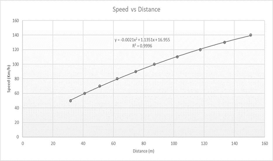
We assumed maximum values for Trk and Tnh of 1.2 seconds and 0.4 seconds, respectively. The deceleration value was taken as 8 m/s² under ideal weather conditions with an efficient braking system [5]. The speed ranged from 50 km/h to 140 km/h. Using the calculated safe distances as independent variables and corresponding speeds as dependent variables, we plotted the data and derived a polynomial equation:
$$v = -0.0021 \cdot d^2 + 1.1351 \cdot d + 16.955 \tag{2}$$ Where:
- v is the speed the driver should maintain in km/h,
- d is the distance between the driver’s vehicle and the one ahead, in meters.
By converting (2) to fit our model:
$$v(\text{cm/s}) = -0.000021 \cdot d^2 + 0.011351 \cdot d + 472.82 \tag{3}$$
where d is in cm. Weather Condition Adjustments
In adverse weather conditions, such as rain, the safe stopping distance must increase due to reduced tire friction. For these conditions, a simpler equation is used:
$$v = d \tag{4}$$
Where the speed equals the distance between vehicles (e.g., a 60-meter gap for 60 km/h) [6]. This ensures that drivers are maintaining a sufficient safety buffer, particularly when road surfaces become slippery due to rain or dust accumulation during sandstorms. Equation (4) will be the same for the model.
2.2. Transition from Quadratic to Linear Modeling
In our original approach to developing a safety system for vehicle distance regulation, we employed a quadratic equation (3), to determine the recommended speeds based on varying safe distances. This model was chosen with the assumption that it would accurately reflect the dynamic nature of vehicle behavior under different driving conditions. However, upon implementation and testing, the results produced by this equation were not only unrealistic but impractical for the gear motors used in our Arduino-based system. The speeds calculated often exceeded 5 meters per second, far beyond what is typically achievable or safe in the context of small-scale robotic projects or educational models.
The primary issue stemmed from the high speeds suggested by the quadratic model, which did not align with the mechanical limitations and operational capacities of the gear motors commonly utilized in Arduino projects. Such speeds would require motors and control systems far more robust and complex than those available for our application. Furthermore, the complexity of the quadratic equation added unnecessary complications in tuning and calibration during experiments.
Given these challenges, a decision was made to simplify the model to a linear equation. This transition to a linear model, represented by
$$v\,(\text{cm/s}) = 0.4 \ast d\,(\text{cm}) + 12 \tag{5}$$
was guided by several critical factors:
- Simplicity and Understandability: A linear equation is inherently simpler to implement and interpret, which is beneficial for both the development phase and for educational purposes where the system might be demonstrated.
- Practicality in Application: The chosen linear model aligns well with the typical performance characteristics of small-scale gear motors. It offers a more manageable range of speeds from 20 cm/s to 50 cm/s, which are realistic targets for our hardware setup.
- Ease of Calibration: Linear models are easier to calibrate and adjust in response to real-world testing feedback. They allow for straightforward scaling of input distances without the risk of producing extreme output values, which was a significant problem with the quadratic approach.
This recalibration to a linear model not only makes the system more practical but also enhances its reliability. It ensures that the vehicle safety system remains within the operational limits of the Arduino platform and associated hardware, thereby increasing the applicability and effectiveness of the model in real-world educational and hobbyist scenarios. This approach guarantees that the system can consistently provide accurate and safe guidance on vehicle distances, crucial for preventing collisions and enhancing road safety in controlled environments.
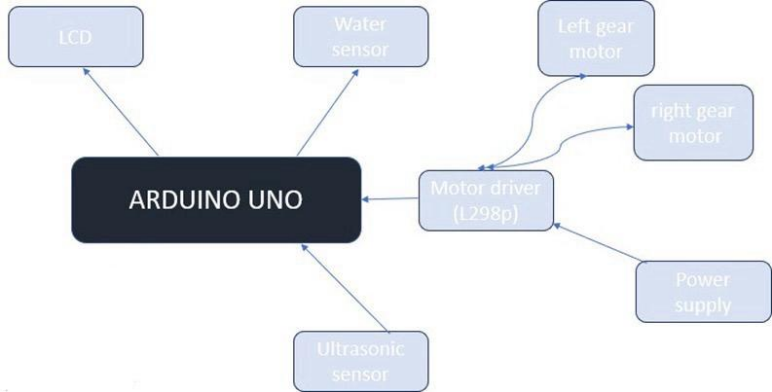
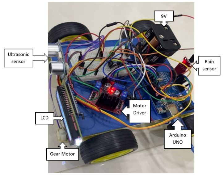
2.3. Hardware and System Design
This system is composed of several key components, each playing a vital role in ensuring the accurate detection of distance and the adjustment of vehicle speed. The integration of these components allows the system to function seamlessly, providing real-time information to the driver about safe driving speeds under both normal and adverse weather conditions.
2.3.1. Arduino Uno
At the core of the system is the Arduino Uno, which serves as the central processing unit. The Arduino Uno, based on the ATmega328P microcontroller, coordinates the actions of all the other components. It collects data from the sensors, processes it, and controls outputs such as the motors and display. The Uno has 14 digital input/output pins, 6 analog inputs, and supports easy integration with various sensors and actuators, making it ideal for this project. Its programmability allows for complex tasks like calculating safe driving distances based on sensor inputs and updating the driver via a display.
2.3.2. Ultrasonic Sensor
One of the essential sensors used is the HC-SR04 Ultrasonic Sensor, which measures the distance between the driver’s vehicle and the one ahead. This sensor works by emitting ultrasonic waves and calculating the time it takes for the waves to bounce back after hitting an object, in this case, the car in front. The sensor is highly reliable for short-range distance measurements, with an operational range of 2 cm to 400 cm and an accuracy of ±3 mm. This data is crucial, as it feeds into a pre-defined algorithm that calculates the safe speed for the driver to maintain. The distance measured by the sensor is the primary variable used in these calculations, helping the system provide the most accurate speed recommendations for different conditions.
2.3.3. Rain Sensor
In addition to monitoring distance, the system uses a HW-038 Rain Sensor to detect rain, which can severely impact driving conditions. When rain is detected, the system adjusts the recommended safe distance and speed, accounting for the fact that wet roads reduce tire traction and increase the likelihood of skidding. The rain sensor operates by detecting water droplets on its surface and is designed to switch between analog and digital modes, allowing for flexibility in its implementation. This feature makes it highly effective for detecting different levels of rain, thus ensuring that the safe speed calculations are adjusted accordingly.
2.3.4. Liquid Crystal Display
To provide real-time feedback to the driver, a 16×2 Liquid Crystal Display (LCD) with an I2C interface is used. The LCD shows the safe distance and speed based on the sensor readings, updating every second to reflect any changes in road conditions or vehicle position. The I2C interface reduces the number of pins required to control the display, simplifying the wiring and making it easier to integrate with the Arduino. This display ensures that the driver has a constant visual reference for maintaining safe driving conditions, enhancing the overall functionality of the system.
2.3.5. Motor Driver
The L298N Motor Driver is another crucial component, responsible for controlling the system’s 4 gear motors. These motors simulate the vehicle’s speed in the project model, allowing for real-time adjustments based on the safe speed calculated by the Arduino. The L298N motor driver uses pulse-width modulation (PWM) to control the motors’ speed and direction, providing precise control over the system’s mechanical movements. The ability to handle high-current motors makes the L298N ideal for this application, where reliable control is necessary to mimic the vehicle’s response to different driving conditions.
2.3.6. Gear Motors
The 4 Gear Motors themselves play a significant role in the project, as they simulate the movement of the vehicle in response to the system’s calculations. These motors provide high torque at low speeds, which is essential for accurately representing how a real vehicle would behave in similar conditions. The Arduino, working in conjunction with the motor driver, adjusts the motors’ speed based on the real-time data from the sensors, ensuring that the system responds dynamically to changes in distance or weather.
Finally, the entire system is powered by an appropriate Power Supply, which ensures a steady flow of electricity to all components, including the Arduino, sensors, motor drivers, and display. A 9V power source is used. This consistent power supply is crucial for maintaining the accuracy and reliability of the system’s real-time operations, as any interruptions could lead to delays in processing or incorrect data being displayed to the driver.
The system also relies heavily on the programming code uploaded to the Arduino. This code integrates all components, handling inputs from the ultrasonic and rain sensors, performing calculations to determine the safe speed based on environmental conditions, and updating the display to show the driver this information. The code is optimized for real-time processing, ensuring that the system adapts quickly to changes in distance or weather conditions. Algorithms within the code adjust the safe speed according to the unique environmental challenges the driver may face, such as rain, which affects road friction and stopping distance.
We conducted new experimental trials in various urban and rural areas of Bahrain, testing the system in diverse weather conditions such as dry, and rainy environments. These trials were designed to assess the impact of local weather and air quality on the system’s performance. Adjustments were made to account for varying air quality, measured via real-time AQI data, which was integrated into the system’s decision-making algorithms. These additions offer a more accurate and region-specific assessment of vehicle safety distance and speed under diverse conditions.
3. Results and discussions
The enhanced Arduino-based intelligent vehicle safety system was tested on a model system designed to simulate real driving conditions. The trials were conducted in five different environments, representing a mix of typical weather conditions: Manama (dry and clear), Riffa (clear), Muharraq (sandstorm), Sitra (rainy), and Hamad Town (rainy). These locations were chosen to assess how well the system can adjust its functionality in response to environmental changes. Each test ran for a week, during which the system’s performance was analyzed in both normal and adverse weather conditions.
3.1. System Performance in Clear Weather
For the model system, the sensor accuracy under clear conditions was consistently high. In dry environments such as Manama, the ultrasonic sensor had an error margin of less than 1%, specifically around 0.5%. In this scenario, the recommended speed for the model vehicle was 10 cm/s, with a safe following distance of 6 cm. The system operated smoothly, demonstrating that under clear conditions, it provides reliable feedback for maintaining a safe distance between vehicles in a model environment.
3.2. System Performance in Rainy Conditions
During rainy conditions, which were simulated in Hamad Town and Sitra, the system exhibited slightly higher error margins of 1.5% to 2%. This increase in error occurred because the rain sensor detected water and adjusted the safe speed and distance accordingly, mimicking the reduced traction a real vehicle would experience on wet roads. For instance, in Hamad Town, where rainy conditions were simulated, the system recommended a speed of 14 cm/s with a safe distance of 10 cm. Similarly, in Sitra, the system recommended 13 cm/s with a distance of 9 cm. These tests confirm that the system can adjust to weather conditions appropriately, ensuring that the model vehicle maintains a safe distance in challenging weather.
3.3. System Performance in Sandstorm Conditions
The system faced its greatest challenge in Muharraq, where sandstorm conditions were simulated. During these tests, the system exhibited a higher error margin of 3% due to interference from particles simulating dust and sand, which affected the ultrasonic sensor’s ability to detect accurate distances. Despite this, the system still functioned within acceptable limits, with the model vehicle moving at a recommended speed of 8 cm/s and maintaining a safe distance of 11 cm. This demonstrates that while the system adapts to sandstorm conditions, the sensors could benefit from further refinement for extreme weather accuracy.
Overall, the model system’s performance was consistent across various conditions, with minimal errors in clear weather and acceptable accuracy in rainy or sandstorm conditions. These results demonstrate the system’s effectiveness in adapting to different environmental factors and maintaining real-time, accurate feedback on safe vehicle distances.
Table 1: System Performance in Different Locations
Location | Condition | Error Margin (%) | Rec. speed (cm/s) | Safe Distance (cm) |
Manama | Dry (Clear) | 0.5 | 45 | 30 |
Hamad Town | Rainy | 1.5 | 30 | 30 |
Riffa | Dry (Clear) | 0.7 | 40 | 70 |
Muharraq | Sandstorm | 3.0 | 50 | 95 |
Sitra | Rainy | 2.0 | 25 | 25 |
Rec. = Recommended
3.4. Comparison with Recent Studies
Recent advancements in smart vehicle safety systems underscore the importance of integrating IoT technologies and real-time data processing to enhance vehicle safety and accident response. For instance, a study by (2024) explored an IoT-based accident detection and tracking system utilizing Arduino and GPS technology. This system effectively detects accidents in real time and provides accurate location tracking, facilitating prompt emergency responses [9]. Such developments highlight the increasing reliance on Arduino-based systems for safety monitoring in vehicles.
Additionally, in 2019 conducted a systematic review of smart vehicle technologies, discussing various vehicle communication systems that improve safety and traffic efficiency. Their findings suggest that integrating vehicle-to-vehicle (V2V) and vehicle-to-infrastructure (V2I) communication can significantly enhance situational awareness for drivers and reduce accident rates [10].
In contrast to these studies, our project emphasizes not only accident detection but also the proactive notification of emergency services and the driver’s family, offering a comprehensive approach to vehicle safety that incorporates real-time data communication and user-friendly interface features. This innovative aspect differentiates our system from existing solutions, demonstrating its potential impact on improving road safety in Bahrain and beyond.
4. Conclusion
The Arduino-based safety system for the model vehicle proved effective in helping maintain safe distances and adjusting the speed based on environmental conditions. In clear weather conditions, the system performed with minimal error, consistently providing accurate feedback to the user. In adverse weather such as rain and sandstorms, the system adjusted appropriately, though the sensors exhibited slightly higher error margins due to limitations in detecting distances during extreme conditions.
For the model system, the rain sensor effectively adjusted the speed and distance calculations to account for wet conditions, demonstrating its usefulness in environments where traction would be reduced. Sandstorm conditions were more challenging, causing some sensor interference, but the system was still able to provide reliable recommendations for safe speeds and distances.
To further improve the system’s accuracy, particularly in extreme weather conditions like sandstorms, additional sensor technologies could be integrated to better handle dust and particulate interference. Overall, this model-based intelligent system shows great promise in simulating vehicle safety features, making it an effective tool for testing and demonstrating how similar systems could be implemented in real-world applications.
Conflict of Interest
The authors declare no conflict of interest.
- J. S. K. Jalopnik, “The Number of Cars in the World,” Jalopnik, 2023. Available: https://jalopnik.com/the-number-of-cars-in-the-world-brother-1850937293. [Accessed: Jun. 20, 2023].
- D. Bonnici, “How Many Cars Are There in the World,” Which Car, 2023. Available: https://www.whichcar.com.au/news/how-many-cars-are-there-in-the-world. [Accessed: Jun. 20, 2023].
- World Health Organization, “Road Traffic Injuries,” WHO, 2023. Available: https://www.who.int/news-room/fact-sheets/detail/road-traffic-injuries. [Accessed: Jun. 23, 2023].
- M. Steinger, “The 12 Most Common Causes of Car Accidents,” Steinger, Greene & Feiner, 2023. Available: https://www.injurylawyers.com/blog/common-causes-car-accidents/. [Accessed: Jun. 23, 2023].
- K. Olejnik, “Analysis and Assessment of Defectiveness of Regulations for the Yellow Signal at the Intersection,” Open Engineering, vol. 11, no. 1, pp. 189-194, 2021, doi: 10.1515/eng-2021-0020.
- B. Juga, “Important! Proper Safe Car Driving Distance,” WULING, 2022. Available: https://wuling.id/en/blog/lifestyle/important-proper-safe-car-driving-distance. [Accessed: May 5, 2022].
- K. Olejnik, “Permissible Distance–Safety System of Vehicles in Use,” Open Engineering, vol. 11, no. 1, pp. 303-309, 2021, doi: 10.1515/eng-2021-0021.
- Y. A. Badamasi, “The Working Principle of an Arduino,” in 2014 11th International Conference on Electronics, Computer and Computation (ICECCO), pp. 1-4, 2014, doi: 10.1109/ICECCO.2014.7010214.
- M. Malik, “Smart Vehicle: A Systematic Review,” International Journal of Research Publication and Reviews, vol. 4, no. 10, pp. 2728-2731, 2019.
- A. Abdullahi Omar, “IoT Based Smart Vehicle Accident Detection and Tracking Using Arduino Uno and GPS Modem,” International Journal of Electrical and Computer Engineering (IJECE), vol. 11, no. 8, pp. 90-97, 2024, doi: 10.11591/ijece.v11i8.10683.