Cross-Sectional Structure of Nested Antiresonant Nodeless Fiber for Single-Mode and Few-Mode Transmission

(This article belongs to the Special Issue on Special Issue on Multidisciplinary Sciences and Advanced Technology 2025 and the Section Optics (OPT))
Export Citations
Cite
Ota, S. and Kubota, H. (2026). Cross-Sectional Structure of Nested Antiresonant Nodeless Fiber for Single-Mode and Few-Mode Transmission. Journal of Engineering Research and Sciences, 5(1), 29–34. https://doi.org/10.55708/js0501003
Shogo Ota and Hirokazu Kubota. "Cross-Sectional Structure of Nested Antiresonant Nodeless Fiber for Single-Mode and Few-Mode Transmission." Journal of Engineering Research and Sciences 5, no. 1 (January 2026): 29–34. https://doi.org/10.55708/js0501003
S. Ota and H. Kubota, "Cross-Sectional Structure of Nested Antiresonant Nodeless Fiber for Single-Mode and Few-Mode Transmission," Journal of Engineering Research and Sciences, vol. 5, no. 1, pp. 29–34, Jan. 2026, doi: 10.55708/js0501003.
Nested Antiresonant Nodeless Fiber (NANF) is a promising candidate for next-generation optical communication systems due to its low-loss, low-latency and low-nonlinearity characteristics. This study focuses on the high degree of design flexibility inherent in NANF, demonstrating through numerical analysis that a single platform can be tailored for two distinct applications required in future networks: single-mode transmission and few-mode transmission for space-division multiplexing. Although low-loss HCFs are by nature multimode fibers, we show that the fiber's modal properties can be actively controlled by adjusting one of the key design parameters: the radius of the inner nested tubes (r2). A design with a smaller radius (r2=5.31 µm) achieves quasi-single-mode transmission by maintaining the fundamental mode loss below 1 dB/km while establishing a loss ratio greater than a factor of ten on a decibel scale relative to higher-order modes. Conversely, a design optimized with a larger radius (r2=7.2 µm) demonstrates quasi-two-mode operation at a wavelength of 1.3 µm, where both the fundamental (0.22 dB/km) and the first higher-order (0.81 dB/km) modes propagate with low loss. These results reveal that NANF is an highly versatile optical fiber platform whose performance can be switched from single-mode to few-mode simply by adjusting one structural parameter. This capability indicates that NANF could play a crucial role in meeting the diverse requirements of future optical communication networks.
1. Introduction
The Hollow-core fibers (HCFs) have been the subject of active research and development for several decades as a next-generation optical fiber technology capable of overcoming the physical limitations of conventional silica glass fibers [1]. Unlike conventional fibers, which guide light by total internal reflection due to the refractive index difference between the core and cladding, HCFs confine light within a hollow, air-filled core based on principles such as the photonic bandgap effect or anti-resonance [2]. This structure endows HCFs with the potential for exceptional properties that are difficult to achieve with solid-core fibers, including ultra-low transmission loss, low nonlinearity, and reduced latency, as light propagates at nearly the speed of light in a vacuum [3].
Among the various HCF architectures, the Nested Antiresonant Nodeless Fiber (NANF), whose adjacent capillaries does not touch each other, has garnered significant low attention for its ability to significantly reduce confinement loss through an optimized cladding design [4]. In 2020, a single-mode NANF was reported to exhibit an attenuation of 0.28 dB/km over the wavelength range between 1510 and 1600 nm and approximately 0.3 dB/km over a 2.8 km fiber between 1500 and 1640 nm [5]. The NANF technology has advanced rapidly, with a recent breakthrough in Double-Nested Antiresonant Nodeless Fiber (DNANF) achieving sub-0.1-dB/km loss from 1320 nm to 2 µm, outperforms that of any existing single-mode fibers [6], [7]. Consequently, it is now regarded as a leading candidate to replace conventional single-mode fibers (SMFs) in next-generation optical communication systems [8], [9].
Looking ahead to the evolution of future optical communication networks, two primary application trajectories for NANF emerge. The first is its use as a single-mode transmission path, leveraging its ultra-low loss characteristics to minimize signal degradation. Achieving this requires a design that exclusively propagates the fundamental mode with low loss while effectively suppressing unwanted higher-order modes that can degrade communication quality [10]. The second trajectory is its application in Space-Division Multiplexing (SDM) technology, aimed at expanding transmission capacity to meet ever-increasing data traffic demands [11] [12]. In this approach, the fiber must be intentionally designed to stably guide multiple propagation modes (few-mode) with low inter-modal crosstalk. Indeed, HCF designs capable of supporting as many as eight core modes with low loss and weak coupling have been reported, demonstrating the feasibility of HCF-based SDM systems [10].
While these two applications have often been pursued as separate research endeavors, this study focuses on the high degree of design freedom inherent in NANF. We aim to comprehensively demonstrate through numerical analysis that by optimizing its structural parameters, a single NANF platform can be tailored to meet the distinct requirements of both single-mode and few-mode transmission. Specifically, by comparing and contrasting a design that intentionally increases higher-order mode loss with a design that simultaneously reduces the loss of both the fundamental and first higher-order modes, we identify the key structural factors that govern the number of transmission modes. Through this investigation, we provide a clear design guideline for the application of NANF in future optical communication systems.
2. Principle of the NANF
The. The light confinement mechanism in a NANF can be explained by the anti-resonant reflecting optical waveguide (ARROW) model, rather than by total internal reflection. The key to this model is the thickness t of the thin glass tubes that constitute the cladding. At specific wavelengths, known as the resonant wavelengths, light resonates within the glass tubes and leaks out into the cladding layer instead of being confined to the core. This resonant wavelength is given by the following equation:
$$
\dot{M}_{\mathrm{Res}}
=
\frac{2t}{m}
\sqrt{n_g^{\,2}-n_{air}^{\,2}}
\tag{1}
$$
Here, t is the thickness of the glass tube, ng is the refractive index of the glass, nair is the refractive index of air, and m is a positive integer. Conversely, in the wavelength range that satisfies the anti-resonance condition, positioned between the resonant wavelengths, light is strongly reflected at the glass-air interfaces and is efficiently confined within the core. This enables low-loss optical transmission. The anti-resonant wavelength is expressed as:
$$
\lambda_{ARes}
=
\frac{4t}{2m-1}
\sqrt{n_g^{\,2}-n_{air}^{\,2}}
\tag{2}
$$
When m is small, the adjacent resonant wavelengths are far apart, NANF can exhibit low-loss characteristics over a broad bandwidth. Critically, this guiding principle applies not only to the fundamental mode but also to higher-order modes under different conditions. Therefore, by varying the structure of the small nested tubes in the cladding (e.g., their radii and thickness), it is possible to control the resonance and anti-resonance conditions for each mode. This is the fundamental principle of mode control in NANF, which allows one design to achieve single-mode transmission by intentionally leaking higher-order modes, while another design enables few-mode transmission by simultaneously guiding multiple modes with low loss.
3. Single-mode NANF
To achieve single-mode transmission, it is essential not only to maintain low loss for the fundamental mode but also to suppress higher-order modes, which can cause signal degradation, by increasing their loss. In this study, we designed a NANF cross-section to achieve this goal and numerically evaluated its mode-dependent loss characteristics. The cross-sectional structure of this design is shown in Fig. 1. Here, R is the core radius, t is the tube thickness, r1 and r2 are the radii of the large and small nested tubes, respectively, and T is the thickness of the outer capillary.
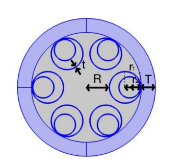
The perfectly matched layer (PML) is placed at the outer capillary to absorb outgoing fields.
For the analysis, the NANF was modeled with a core radius R of 15 µm and a glass tube thickness t of 0.42 µm. The radii of the large and small nested tubes were set to r1=10.62 µm and r2=5.31 µm, respectively.
Simulations were performed using COMSOL Multiphysics®, a numerical analysis software based on the finite element method (FEM). The computational domain was defined to search for ten modes around an effective refractive index of 1, and the complex effective refractive index was calculated for each mode. PML was applied to the outermost layer of the structure to ensure that guided modes were absorbed without reflection at the interface. The loss evaluated in this study is the “confinement loss,” which arises solely from the light-confining ability of the ideal structure, neglecting structural non-uniformities and material absorption loss. The wavelength dependence of the refractive index for silica was calculated using the Sellmeier equation.
The confinement loss was calculated from the following equation, where α is the imaginary part of the effective refractive index.
$$
\textit{Confinement Loss}\,[\mathrm{dB/km}]
=
\frac{\alpha \log_{10} e}{100}
\tag{3}
$$
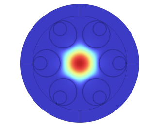
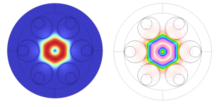
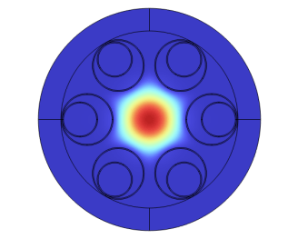
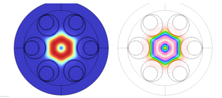
Figure 2 shows the electric field distribution at a wavelength of 1.3 µm for the fundamental mode, and Fig.3 shows that of the first higher-order mode, which had the lowest loss among the higher-order modes. The right-hand side of Fig.3 shows the contour lines of the electric field distribution, which illustrate the large electric field leakage. As is evident from this figures, the NANF has higher-order modes in addition to the fundamental mode. They are confined within the core in the same wavelength, indicating that this structure is inherently a multimode fiber. However, by setting an appropriate cross-sectional parameter, NANF can be operate in quasi-single-mode. The calculated wavelength dependence of the confinement loss is shown in figure 4. The vertical and the horizontal axis represent the confinement loss and the wavelength, respectively. The red, the yellow, and the black lines represent the losses of the fundamental mode, the first higher-order mode, and the other higher-order mode, respectively. The results indicate that the fundamental mode maintains a low confinement loss of less than 1 dB/km over the broad wavelength range of 1.0 µm to 1.7 µm. Table 1 shows the confinement losses for each wavelength. Furthermore, within this low-loss window, the loss difference between
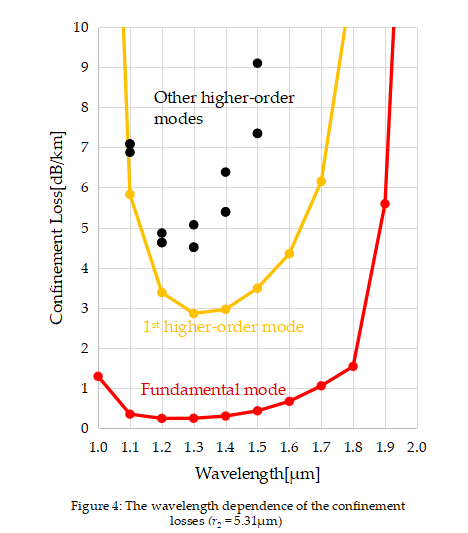
the fundamental mode and the lowest-loss higher-order mode is more than a factor of ten on a decibel scale. This significant loss differential ensures that even if higher-order modes are excited, they are rapidly attenuated as they propagate through the fiber, meaning that effectively only the fundamental mode is transmitted. Thus, a broadband quasi-single-mode NANF is achievable.
Table 1: The confinement losses for each wavelength (r2 = 5.31µm)
| Wavelength (µm) | Fundamental Mode (dB/km) | First Higher-Order Mode (dB/km) |
|---|---|---|
| 1.0 | 1.29 | 26.26 |
| 1.1 | 0.34 | 6.88 |
| 1.2 | 0.23 | 4.62 |
| 1.3 | 0.24 | 2.85 |
| 1.4 | 0.29 | 2.96 |
| 1.5 | 0.42 | 3.49 |
| 1.6 | 0.66 | 4.35 |
| 1.7 | 1.05 | 6.15 |
| 1.8 | 1.53 | 11.29 |
| 1.9 | 5.59 | 29.46 |
4. Two-mode NANF
In contrast to single-mode transmission, applications in Space-Division Multiplexing (SDM) require a fiber design that intentionally and stably propagates multiple modes with low loss. This section investigates thefeasibility of realizing a quasi-two-mode NANF that guides both the fundamental mode and the first higher-order mode with low loss. The core strategy in this design is to adjust the cladding structure, specifically the radius of the inner tube r2. Because the space formed between the large tube r1 and the small tube r2 was considered to be strongly related to the light confinement and the resonance conditions of higher-order modes, we specifically varied the value of r2 in this simulation. The objective was to create a wavelength region where both the fundamental and first higher-order modes simultaneously satisfy the antiresonance condition.
In the analysis, the core radius R was set to 15 µm and the tube thickness t to 0.42 µm, in accordance with the single-mode design described in Section 3. The radius r₂ was optimized to minimize the loss of the first higher-order mode at a wavelength of 1.3 µm. In this process, the range of r2 was explored around 7 µm to ensure that the mode field diameter (MFD) is approximately 10 µm, which is comparable to that of a standard SMF. The loss reached its minimum when r₂ was 7.2 µm. Figure 5 shows the electric field distribution at a wavelength of 1.3 µm for the fundamental mode. Figure 6 presents the electric field distribution of the lowest-loss higher-order modes for this structure. The right-hand side of figure 6 shows the contour lines of the electric field distribution. The fundamental mode shown in figure 5 exhibits no noticeable difference from that in figure 2, whereas the first higher-order mode shown on right-hand side of figure 6 exhibits slightly stronger confinement than that shown on the right-hand side of figure 3.
The wavelength dependence of the confinement loss for this optimized structure is shown in figure 7. The vertical and the horizontal axis represent the confinement loss and the wavelength, respectively. The red, the yellow, and the lines represent the losses of the fundamental mode, the first higher-order mode, and black dots represent those of other higher-order modes, respectively. Table 2 shows that at a wavelength dependence confinement loss for the fundamental and first higher-order modes. at a wavelength of 1.3 µm, the losses for the fundamental and first higher-order modes are 0.22 dB/km and 0.81 dB/km, with corresponding values of 5.28*10-12 and 1.93*10-11, respectively, indicating that both modes are guided with low attenuation. Meanwhile, the minimum loss of the second higher-order mode was 3.43 dB/km at a wavelength of 1.2 µm, providing a comparable loss margin to that of quasi-single mode NANF. This result suggests the possibility of operation as a quasi-two-mode fiber, capable of propagating the two intended modes while suppressing other unwanted higher-order modes.
Furthermore, the dispersion characteristics of this design were evaluated, with the results shown in Fig. 8. The horizontal axis is wavelength, and the vertical axis is dispersion; the red line indicates the fundamental mode, and the yellow line indicates the first higher-order mode. As shown in the figure, the dispersion slope is well-suppressed for both the fundamental and higher-order modes within the primary transmission band of 1.1 µm to 1.8 µm. Specifically, at a wavelength of 1.3 µm, the dispersion was 2.57 ps/nm/km for the fundamental mode and 6.36 ps/nm/km for the first higher-order mode. Notably, the dispersion of the fundamental mode is kept small over a wide wavelength range compared to standard single-mode fiber, which is advantageous for easing communication system design. The differential mode delay (DMD) was calculated to be few thousands ps/km in the low-loss wavelength range. This value is less than half of that of a typical step-index fiber but is about two orders of magnitude larger than that of a graded-index fiber. These findings indicate that the hollow-core structure of HCF does not necessarily eliminate dispersion nor reduce the differential mode delay. Additionally, low-dispersion bandwidth of the higher-order mode tends to be narrower than that of the fundamental mode. Therefore, controlling dispersion, reducing DMD, and expanding the transmission bandwidth of higher-order modes also remain challenges for future work.
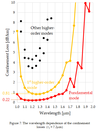
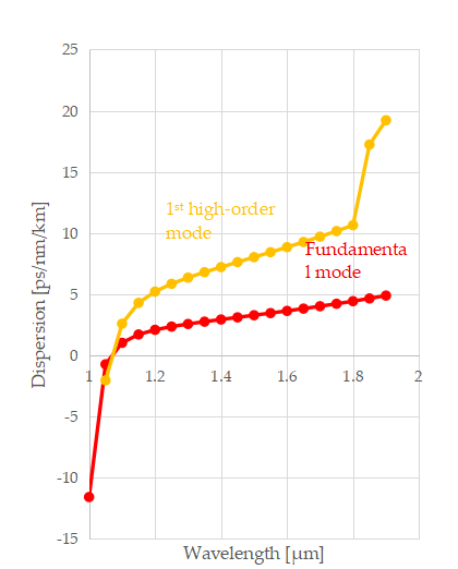
Table 2: The confinement losses for each wavelength (r2 = 7.2µm)
| Wavelength (µm) | Fundamental Mode (dB/km) | First Higher-Order Mode (dB/km) |
|---|---|---|
| 1.00 | 0.800 | 7.134 |
| 1.05 | 0.341 | 2.578 |
| 1.10 | 0.221 | 1.446 |
| 1.15 | 0.183 | 1.031 |
| 1.20 | 0.177 | 0.856 |
| 1.25 | 0.191 | 0.795 |
| 1.30 | 0.221 | 0.808 |
| 1.35 | 0.266 | 0.890 |
| 1.40 | 0.348 | 1.032 |
| 1.45 | 0.482 | 1.229 |
| 1.50 | 0.612 | 1.539 |
| 1.55 | 0.785 | 1.972 |
| 1.60 | 0.831 | 2.685 |
| 1.65 | 1.186 | 3.967 |
| 1.70 | 2.358 | 4.146 |
5. Conclusion
In this study, we numerically demonstrated that the design flexibility of NANF can be leveraged to create fibers tailored for two distinct communication applications: single-mode and few-mode transmission. In a design where the inner nested tube radius r2 was set to a half of r1, we successfully achieved a large loss ratio of more than a factor of ten between the fundamental mode and the higher-order modes while keeping the fundamental mode loss below 1 dB/km, thus demonstrating the feasibility of effective single-mode transmission. In contrast, when the r2 was increased to 7.21 µm, both the fundamental mode with a loss of 0.22 dB/km and the first higher-order mode with a loss of 0.81 dB/km exhibit low confinement loss at a wavelength of 1.3 µm, demonstrating its capability to operate as a quasi-two-mode fiber. This study agrees with the findings of Ref. [3] regarding fundamental mode loss, which validates the current method given their structural similarities.
In conclusion, NANF is an extremely versatile platform whose modal characteristics can be actively controlled simply by making minor changes to the cladding structure, specifically by adjusting a single parameter, r2. While other studies utilize numerous design elements to achieve low-loss characteristics across many modes, this work specifically investigates a few-mode regime within the NANF structure [10]. Consequently, it is considered challenging to realize low attenuation for a large number of modes simultaneously, given the limited number of controllable parameters. This high degree of design freedom strongly suggests that NANF can be a powerful solution to meet the diverse and evolving demands of future optical communication networks.
- W. Ding, Y. Y. Wang, S. F. Gao, M. L. Wang, P. Wang, “Recent Progress in Low-Loss Hollow-Core Anti-Resonant Fibers and Their Applications,” IEEE Journal of Selected Topics in Quantum Electronics, 2019, doi: 10.1109/JSTQE.2019.2957445.
- N.M. Litchinitser, A.K. Abeeluck, C. Headley, B.J. Eggleton, “Antiresonant reflecting photonic crystal optical waveguides,” OPTICS LETTERS, 2002, doi: 10.1364/ol.27.001592.
- F. Poletti, “Nested antiresonant nodeless hollow core fiber,” OPTICS EXPRESS, 2014, doi: 10.1364/oe.22.023807.
- M. S. Habib, O. Bang, M. Bache, “Low-loss single-mode hollow-core fiber with anisotropic anti-resonant elements,” Opt Express, 2016, doi: 10.1364/oe.24.008429.
- G. T. Jasion, T.D. Bradley, K. Harrington, H. Sakr, Y. Chen, E.N. Fokoua, “Recent Breakthroughs in Hollow Core Fiber Technology,” 2021 Optical Fiber Communications Conference and Exhibition (OFC), San Francisco, CA, USA, 2021.
- E. N. Fokoua, S.A. Mousavi, G.T. Jasion, D.J. Richardson, F. Poletti, “Loss in hollow-core optical fibers: mechanisms, scaling rules, and limits,” Advances in Optics and Photonics, 2023, doi: 10.1364/aop.470592.
- G. T. Jasion, H. Sakr, J. R. Hayes, S. R. Sandoghchi, L. Hooper, E. N. Fokoua、A. Saljoghei, H. C. Mulvad, M. Alonso, A. Taranta, et al., “0.174 dB/km Hollow Core Double Nested Antiresonant Nodeless Fiber (DNANF),” 2022 Optical Fiber Communications Conference and Exhibition (OFC), San Diego, CA, USA, 2022.
- J. Hecht, “Is Nothing Better Than Something?,” OPTICS & PHOTONICS NEWS , 2021.
- Y. Chen, M. N. Petrovich, E. N. Fokoua, A. I. Adamu, M. R. A. Hassan, H. Sakr, R. Slavík, S. B. Gorajoobi, M. Alonso, R. F. Ando, A. Papadimopoulos, et al., “Hollow Core DNANF Optical Fiber with <0.11 dB/km Loss,” OFC 2024, San Diego California, United States, 2024.
- B. Wang, W. Gao, X. Wang, P.K. Chu, S.Lou, “Low-Loss and Weakly Coupled Eight-Mode Nodeless Hollow-Core Anti-Resonant Fiber With Three-Layer Nested Tubes in Each Cladding Unit,” Journal of Lightwave Technology, 2025, doi: 10.1109/JLT.2024.3507111.
- T. Morioka, “New generation optical infrastructure technologies:”EXAT initiative” towards 2020 and beyond,” 14th Opt Electronics and Communications Conference, Hong Kong, China, July, 2009.
- B.J. Puttnam, G. Rademacher, and R.S.Luis, “Space-division multiplexing for optical fiber communications,” Optica, 2021, doi: 10.1364/optica.427631.
No related articles were found.